


Grandstream Networks, Inc.
1297 Beacon Street, 2nd Floor
Brookline, MA 02446. USA
Tel : +1 (617) 566 – 9300
Fax: +1 (617) 249 – 1987
www.grandstream.com
For Warranty and RMA information, please visit www.grandstream.com
GXP2120/2110 Enterprise IP Phone
Quick Start Guide
EN
The GXP2120/2110 is not pre-configured to support or carry emergency calls to any type of hospital, law enforcement agency, medical care unit (“Emergency Service(s)”) or any other kind of Emergency
Service. You must make additional arrangements to access Emergency Services. It is Your responsibility to purchase SIP-compliant Internet telephone service, properly configure the GXP2120/2110 to use that service, and periodically test your configuration to confirm that it works as You expect. If You do not do so, it is Your responsibility to purchase traditional wireless or landline telephone services to access
Emergency Services.
GRANDSTREAM DOES NOT PROVIDE
CONNECTIONS TO EMERGENCY SERVICES VIA
THE GXP2120/2110. NEITHER GRANDSTREAM
NOR ITS OFFICERS, EMPLOYEES OR AFFILIATES
MAY BE HELD LIABLE FOR ANY CLAIM, DAMAGE, OR LOSS, AND YOU HEREBY WAIVE ANY AND
ALL SUCH CLAIMS OR CAUSES OF ACTION ARIS-
ING FROM OR RELATING TO YOUR INABILITY TO USE THE GXP2120/2110 TO CONTACT
EMERGENCY SERVICES, AND YOUR FAILURE TO MAKE ADDITIONAL ARRANGEMENTS TO ACCESS EMERGENCY SERVICES IN ACCORDANCE
WITH THE IMMEDIATELY PRECEDING PARA-
GRAPH.
1
PRECAUTIONS:
WARNING: Please DO NOT power cycle the GXP2120/2110 when the LED lights are flashing during system boot up or firmware upgrade. You may corrupt
firmware images and cause the unit to malfunction.
WARNING: Use only the power adapter included in the GXP2120/2110 package. Using an alternative non-qualified power adapter may possibly damage the unit.
OVERVIEW
The GXP2120/2110 IP Phones has sleek outer design and delivers excellent call quality and enterprise grade feature set that includes advanced XML capabilities, multi-party conferencing, multi-language support, presence and BLF (busy lamp field), security protection, automated provisioning, and broad compatibility with leading SIP platforms. The GXP2110 offers 4 lines, 18 programmable keys, 3
XML programmable soft keys and the GXP2120 offers 6 lines, 4 XML programmable soft keys, and 7 programmable keys.
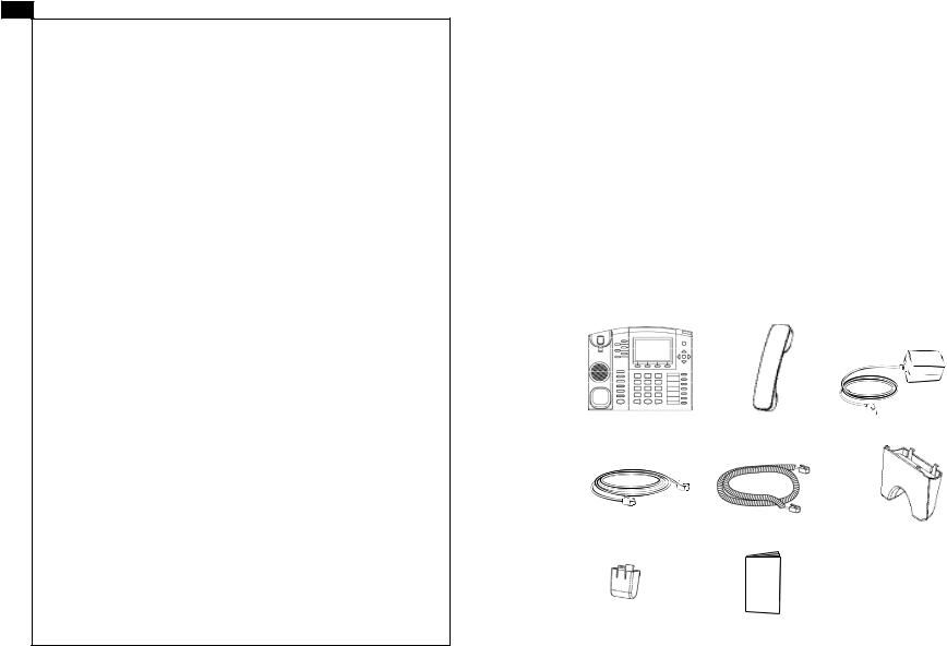
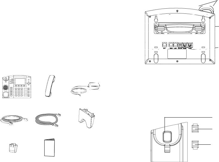
PACKAGE CONTENTS:
1 X Phone Main Case |
1 X Handset |
1 X 5V Power adapter |
1x Ethernet Cable |
1 X Phone Cord |
1 |
X High Stand |
|
1 |
X Short Stand |
|
|
|
2 X Wall Mount |
1 X Quick Install Guide |
Spacers |
2 |
|
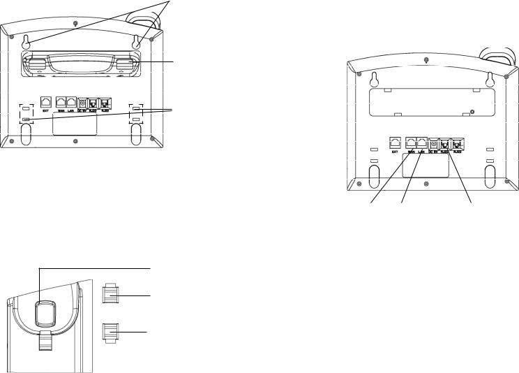
PHONE SETUP:
Wall Mount Holes are available
Slot for the phone stand if placing the phone on the table
Slot for the wall mount spacers if placing the phone on the wall
Installing the phone (Wall Mount):
1.Attach the two wall mount spacers to the slot for wall mount spacers on the back of the phone.
2.Attach the phone to the wall via the wall mount hole
3.Pull out the tab on from the handset cradle. (See figure below)
4.Rotate the tab and plug it back into the slot with the extension up to hold the handset while the phone is mounted on the wall. (See figure below)
Handset Rest
Tab with extension up
Tab with extension down
Installing the phone (Phone Stand) :
For installing the phone on the table with the phone stand, attach the phone stand to the bottom of the phone where there is a slot for the phone stand. (Upper half, bottom part).
CONNECTING THE PHONE:
Refer to the illustration below when following the setup instructions .
Extenstion |
|
|
|
Handset Port |
|
|
|
|
|
|
|
Module Port |
|
|
|
||
|
|
|
|
||
|
|
|
|
|
|
PC Port LAN Port Power Headset Port
To setup the GXP2120/2110, follow the steps below:
1.Connect the handset and main phone case with the phone cord.
2.Connect the LAN port of the phone to the RJ-45 socket of a hub/switch or a router (LAN side of the router) using the Ethernet cable.
3.Connect the 5V DC output plug to the power jack on the phone; plug the power adapter into an electrical outlet.
4.The LCD will display provisioning or firmware upgrade information. Before continuing, please wait for the date/time display to show up.
5.Using the phone embedded web server or keypad configuration menu, you can further configure the phone using either a static IP or DHCP.
3 |
4 |
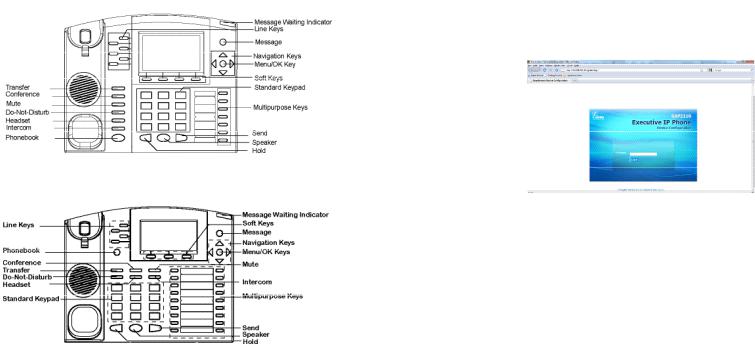
Tips For Using the Keypad:
GXP2120 Keypad
GXP2110 Keypad
1.To access the MENU, press the round MENU button.
2.Navigate the menu by using the UP/DOWN and LEFT/RIGHT buttons.
3.Press the round MENU button to confirm a menu selection.
4.Delete an entry by pressing the MUTE button.
5.The phone automatically exits MENU mode with an incoming call, the phone is off-hook or the MENU mode is left idle for 20 seconds.
PHONE CONFIGURATION:
Configure the GXP2120/2110 using a Web Browser:
1. Ensure your phone is powered up and connected to the Internet.
5 2. Press MENU button to go into menu of the phone.
3.Press down arrow button to Status and press MENU button to see IP address.
4.Type the phone’s IP address in your PC browser. (See figure below)
5.The default administrator password is “admin”; the default end-user password is “123”.
Configure the GXP2120/2110 using the Keypad:
1.Make sure the phone is idle
2.Press the “MENU” button to access the keypad MENU to configure the phone.
3.Select MENU-> Config, to configure settings for SIP Proxy, Outbound Proxy, SIP User ID, SIP Auth ID, SIP Password
4.Follow MENU options to configure the basic features of the phone – for example: the IP address if using a static IP. For details, please check GXP Series
User Manual.
5.Please contact your ITSP for additional settings that may be necessary to configure the phone.
GXP2120/2110 EXT EXpansion MODULE
The GXP2120/2110 EXT module is an ideal solution for the busy enterprise environment looking to add the ability to receive and dispatch calls efficiently.
Each expansion module has 56 programmable buttons. The GXP phone supports up to two EXT Modules, adding 112 fully programmable phone extensions to the phone.
Note: The extension module is an additional accessory for the GXP2120/2110 and is not included in the box
6
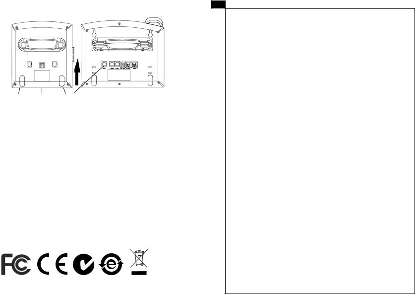
Installing the Extension Module for the GXP2120/2110
Extension Stand Power Extension Connector
Setup |
Port |
|
1.Attach the stand to the extension module
2.Connect the extension module with the phone main body by sliding it into the bracket on the side of the phone.
3.Connect the Extension module to the GXP main body using the cable provided.
4.Connect the extension module to an electrical power outlet using the universal power adapter provided.
ConfiguraTION
1. Log into the GXP phone web configuration interface to configure the multipurpose keys on the extension module.
2. Click on “EXT1” or “EXT2” depending on which extension module you wish to configure.
3. Configure the multipurpose keys for the purpose desired: Speed Dial, BLF, Eventlist BLF, or Presence Watcher.
Note: For the detailed user manual, please download from:
7 http://www.grandstream.com/support/gxp_series/general/gxp_support.html
FR
Le GXP2120/2110 n’est pas pré configuré pour soutenir ou réaliser des appels d’urgence à tout type d’hôpital, organisme d’application de la loi, unité
de soins médicaux ou tout autre type de service d’urgence. Vous devez prendre des dispositions supplémentaires pour accéder à des services d’urgence. Il est de votre responsabilité d’acheter un service de téléphonie par Internet, configurer correctement le
GXP2120/2110 pour utiliser ce service et de tester périodiquement votre configuration pour vérifier qu’il fonctionne comme prévu. Si vous ne procédez pas ainsi, est de votre responsabilité d’acheter des services de téléphonie traditionnels sans fil ou fixes pour accéder aux services d’urgence.
GRANDSTREAM NE FOURNIT PAS
DE CONNEXIONS AUX SERVICES D’URGENCE
VIA LE GXP2120/2110. NI GRANDSTREAM NI SES
DIRIGEANTS, SES EMPLOYÉS OU SES FILIALES
NE PEUVENT ETRE TENUS RESPONSABLES DE TOUTE RÉCLAMATION, DOMMAGE OU PERTE ET
VOUS RENONCEZ À TOUTE RÉCLAMATION OU
CAUSE D’ACTION RESULTANT DE OU EN RELA-
TION AVEC VOTRE INCAPACITE D’UTILISER LE GXP2120/2110 POUR CONTACTER LES SERVICES D’URGENCE, ET VOTRE ECHEC A METTRE
EN PLACE DES ARRANGEMENTS SUPPLE-
MENTAIRES POUR ACCEDER AUX SERVICES
D’URGENCE CONFORMEMENT AU PARAGRAPHE
PRECEDENT.
8
PRECAUTIONS:
ALERTE: Veuillez ne pas redémarrer le GXP2120/2110 lorsque les voyants clignotent durant le démarrage du système ou la mise à jour du firmware. Ca peut corrompre l’image du firmware et causer un dysfonctionnement de l’unité. ALERTE: N’utilisez que le boîtier d’alimentation fourni dans le pack GXP2120/2110. L’utilisation d’un autre boîtier d’alimentation non qualifié peut endommager l’unité.
PRESENTATION
Les Téléphones IP GXP2120/2110 ont un design extérieur élégant et offrent une excellente qualité d’appel et un ensemble de caractéristiques de qualité d’entreprise qui inclut des capacités XML avancées, multi conférence, le support de plusieurs langues, la présence et BLF, la sécurité de protection, d’approvisionnement automatisé, et une large compatibilité avec les principales plates-formes SIP. Le GXP2110 offre 4 lignes, 18 touches programmables, 3 touches programmables XML et le GXP2120 dispose de 6 lignes, 4 touches programmables XML, et 7 touches programmables.
CONTENU DU PACK :
1 X Appareil téléphonique 1 X Combiné |
1 X Boîtier |
|
d’alimentation 5V |
||
|
1 X Câble Ethernet |
1 X Câble téléphonique |
1X |
Positionneur Elevé |
|
|
1X |
Petit Positionneur |
|
2 X Support Mural |
1 X Guide d’installation |
|
|
Entretoises |
||
9 |
rapide |
||
|
|||
|
|
INSTALLATION DU TELEPHONE:
Les trous pour le montage sur le mur sont disponibles
La fente pour le positionneur téléphonique si vous allez placer
le téléphone sur la table
La fente pour les

 entretoises en
cas de montage du téléphone sur le mur
Installation du téléphone (montage sur le mur):
1.Fixez les deux entretoises dans la fente au dos du téléphone pour le montage mural.
2.Joindre le téléphone au mur par le trou du support mural.
3.Tirez la languette du support du combiné. (Voir figure ci-dessous)
4.Faire pivoter l’onglet et branchez-le dans la fente, avec l’extension jusqu’au tenir le casque d’écoute alors que le téléphone est monté sur le mur. (Voir figure ci-dessous)
Combiné Repos
Onglet avec extension vers le haut
Onglet avec extension vers le bas
10

Installation du téléphone (Positionneur téléphonique):
“Pour installer le téléphone sur la table avec le positionneur du téléphone, joignez ce dernier à la base du téléphone où il y a une fente.
(Moitié supérieure, une partie du bas).
CONNECTER LE TELEPHONE:
Reportez-vous à l’illustration ci-dessous en suivant les instructions d’installation.
Port pour |
|
|
|
Port du |
le module |
|
|
|
casque |
|
|
|
||
d’extension |
|
|
|
d’ecoute |
Port PC Port LAN Alimentation Port Combiné
Pour installer le GXP2120/2110, suivez les instructions ci-dessous :
1.Connectez le combiné et le boîtier de téléphone principal avec le câble téléphonique.
2.Connecter le port LAN de votre téléphone au port RJ-45 d’un concentrateur / commutateur ou un routeur (côté LAN du routeur) à l’aide du câble Ethernet.
3.Connectez la fiche de sortie 5V DC à la prise d’alimentation sur le téléphone, branchez l’adaptateur dans une prise électrique.
4.Le LCD va afficher les informations de provisionnement ou de mise à jour du firmware. Avant de continuer, veuillez patienter jusqu’à que la date/heure s’affiche.
5.En utilisant le serveur web intégré du téléphone ou le menu de la configuration du téléphone, vous pouvez le configurer en utilisant soit IP statique ou DHCP.
11
Conseils d’utilisation du clavier :
GXP2120
GXP2110
1.Pour accéder au MENU, appuyez sur le bouton circulaire MENU.
2.Naviguez dans le menu en utilisant les boutons HAUT/BAS et GAUCHE/
DROITE.
3.Appuyez sur le bouton circulaire MENU pour confirmer la sélection.
4.Supprimer une entrée en appuyant sur le bouton MUET.
5.Le téléphone quitte automatiquement le mode MENU quand il y a un appel entrant, le téléphone est décroché, ou lorsque le mode MENU est laissé inactif pendant 20 secondes.
CONFIGURATION DU TELEPHONE :
Configurer le GXP2120/2110 en utilisant le Navigateur web :
1. Vérifiez que votre téléphone est sous tension et connecté à Internet.
2. Appuyez sur le bouton MENU pour aller dans le menu du téléphone.
12
 Loading...