


 Loading...
Repair and Parts
Visit our website;
http://MAGNUM.Graco.com
X5 |
™ |
™ |
ProX7 |
™ |
™ |
312667K |
|
EN |
|||||||
, |
X7, |
|
& ProX9 Airless Sprayers |
- For portable spray applications of architectural paints and coatings. For professional use only-
Models 262800, 262805, 261815, 261820
See page 3 for model and series information including dispense rate, recommended hose length, guns, and maximum working pressure.
IMPORTANT SAFETY INSTRUCTIONS.
 Read all warnings and instructions in this manual. Save these instructions.
Related Manual
312001
X5 and X7 Models ONLY: Use water based or mineral-spirit type material only. Do not use materials having flash points lower than 70°F (21°C). This includes, but is not limited to, acetone, xylene, toluene, or naptha. For more information about your material request MSDS from distributor or retailer.
MAGNUM X5 |
MAGNUM ProX7 |
MAGNUM ProX9 |
Model: 262800 |
Model: 261815 |
Model: 261820 |
Series A, B, C, D |
Series A |
Series A |
ti11304a |
|
|
|
|
ti9369a |
ti9368a |
|
MAGNUM X7 |
MAGNUM ProX7 |
MAGNUM ProX9 |
|
Model: 262805 |
|||
Model: 261815 |
Model: 261820 |
||
Series A, B, C |
|||
Series B |
|||
|
Series B |
||
|
|
ti11305a |
ti9369b |
|
|
|
ti16976a |
Table of Contents
Table of Contents
Table of Contents . . . . . . . . . . . . . . . . . . . . . . . . . . 2 Specifications . . . . . . . . . . . . . . . . . . . . . . . . . . . . . 3 Getting Started
Fold-n-Store™ Cart (ProX, Series A Sprayers Only) . . . . . . . . . . . . . . . . . . . . . . . . . . . . . . . . . . 3
Warnings . . . . . . . . . . . . . . . . . . . . . . . . . . . . . . . . . 4 Component Identification . . . . . . . . . . . . . . . . . . . . 8 Installation . . . . . . . . . . . . . . . . . . . . . . . . . . . . . . . 10
Grounding and Electric Requirements . . . . . . . 10 Thermal Overload . . . . . . . . . . . . . . . . . . . . . . . 10
Operation . . . . . . . . . . . . . . . . . . . . . . . . . . . . . . . . 11
Trigger Lock . . . . . . . . . . . . . . . . . . . . . . . . . . . 11 Pressure Relief Procedure . . . . . . . . . . . . . . . . 11 Pressure Control Knob Settings . . . . . . . . . . . . 11
General Repair Information . . . . . . . . . . . . . . . . . 12 Basic Troubleshooting . . . . . . . . . . . . . . . . . . . . . 13 Advanced Troubleshooting . . . . . . . . . . . . . . . . . 18
General Problem: Motor Does Not Operate . . . 18 General Problem: Circuit Breaker is Tripping . . 21 General Problem: Erratic Motor Operation . . . . 22 General Problem: Low or Fluctuating Output . . 23 General Problem: Excessive Pressure Build Up 24
Motor Diagnostics (X5 and X7) . . . . . . . . . . . . . . . 25 Motor Diagnostics (ProX7 and ProX9) . . . . . . . . . 25 Pressure Control Switch Diagnostics . . . . . . . . . 26
Control Board Diagnostics (ProX7 and ProX9) . . 27 Control Board Diagnostics (X5 and X7) . . . . . . . . 27 Pump Diagnostics . . . . . . . . . . . . . . . . . . . . . . . . . 27 List of Kits (Series A) . . . . . . . . . . . . . . . . . . . . . . . 28 List of Kits (Series B, C, D) . . . . . . . . . . . . . . . . . . 29 Parts . . . . . . . . . . . . . . . . . . . . . . . . . . . . . . . . . . . . 30
X5 Model 262800 (Series A) . . . . . . . . . . . . . . . 30 X5 Model 262800 (Series B, C, D) . . . . . . . . . . 33 X7 Model 262805 (Series A) . . . . . . . . . . . . . . . 36 X7 Model 262805 (Series A) . . . . . . . . . . . . . . . 38 X7 Model 262805 (Series B, C) . . . . . . . . . . . . . 39 X7 Model 262805 (Series B, C) . . . . . . . . . . . . . 40 X7 Model 262805 (Series B, C) . . . . . . . . . . . . . 41
ProX7 and ProX9 Models 261815 and 261820 (Series A, B) . . . . . . . . . . . . . . . . . . . . . . . . 42
ProX7 and ProX9 Models 261815 and 261820 (Series A) . . . . . . . . . . . . . . . . . . . . . . . . . . 44
ProX7 and ProX9 Models 261815 and 261820 (Series B) . . . . . . . . . . . . . . . . . . . . . . . . . . 45
Wiring Diagrams . . . . . . . . . . . . . . . . . . . . . . . . . . 46
X5 and X7 Models 262800 and 262805 (Series A)
46
ProX7 and ProX9 Models 261815 and 261820 . 48
Technical Data . . . . . . . . . . . . . . . . . . . . . . . . . . . . 49 Graco Standard Warranty . . . . . . . . . . . . . . . . . . . 50
2 |
312667K |
Specifications
Specifications
This equipment is not intended for use with flammable or combustible materials used in places such as cabinet shops or other “factory”, or fixed locations. If you intend to use this equipment in this type of application, you must comply with NFPA 33 and OSHA requirements for the use of flammable and combustible materials.
|
|
|
|
|
Maximum Working |
|||
|
|
Dispense Rate |
Hose Length and |
Gun |
|
Pressure |
|
|
|
|
|
|
|
||||
Model Name |
Series |
gpm (lpm) |
Diameter |
Model |
PSI |
MPa |
bar |
|
|
|
|
|
|
|
|
|
|
MAGNUM X5 |
A, B, C |
0.24 gpm |
1/4 in. x 25 ft |
SG2 |
2800 |
19 |
193 |
|
(0.91 lpm) |
(6.4 mm x 7.5 m) |
|||||||
|
|
|
|
|
|
|||
|
|
|
|
|
|
|
|
|
MAGNUM X5 |
D |
0.27 gpm |
1/4 in. x 25 ft |
SG2 |
3000 |
21 |
207 |
|
(1.02 lpm) |
(6.4 mm x 7.5 m) |
|||||||
|
|
|
|
|
|
|||
|
|
|
|
|
|
|
|
|
MAGNUM X7 |
A, B, C |
0.31 gpm |
1/4 in. x 25 ft |
SG2 |
3000 |
21 |
207 |
|
(1.17 lpm) |
(6.4 mm x 7.5 m) |
|||||||
|
|
|
|
|
|
|||
|
|
|
|
|
|
|
|
|
MAGNUM |
A, B |
0.34 gpm |
1/4 in. X 50 ft |
SG3 |
3000 |
21 |
207 |
|
ProX7 |
(1.29 lpm) |
(6.4 mm x 15 m) |
||||||
|
|
|
|
|
||||
|
|
|
|
|
|
|
|
|
MAGNUM |
A, B |
0.38 gpm |
1/4 in. X 50 ft |
SG3 |
3000 |
21 |
207 |
|
ProX9 |
(1.44 lpm) |
(6.4 mm x 15 m) |
||||||
|
|
|
|
|
||||
|
|
|
|
|
|
|
|
|
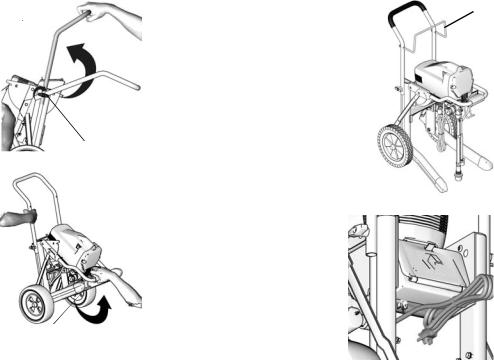
Getting Started
Fold-n-Store™ Cart (ProX, Series A Sprayers Only)
1. Unfold Fold-n-Store |
a |
d |
|
handle (a) and align |
4. Install hose rack (d) to frame |
||
|
|||
as shown. |
|
handle. Install lock nuts. |
|
|
|
Tighten securely. |
2. Tighten wingnuts (b).
 b ti9675a
3.Grasp cart handle securely with one hand. With the other hand, lift and pull handle (a) located in front of sprayer frame, toward you. Lift up front of sprayer until you hear a
click and the cart is |
c |
|
locked in place. |
ti9679a |
5.Secure power cord in clip
(e) located underneath storage compartment.
e
ti9369a
ti9719a
312667K |
3 |

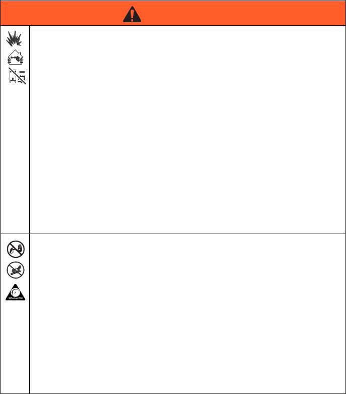
Warnings
Warnings
The following warnings are for the setup, use, grounding, maintenance, and repair of this equipment. The exclamation point symbol alerts you to a general warning and the hazard symbols refer to procedure-specific risks. Refer back to these warnings. Additional, product specific warnings may be found throughout the body of this manual where applicable.
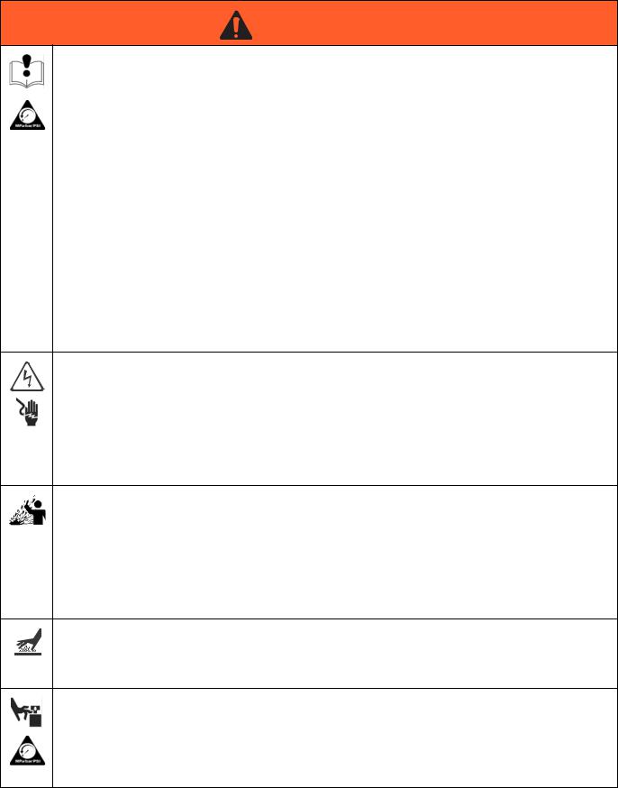
 WARNING
GROUNDING
This product must be grounded. In the event of an electrical short circuit, grounding reduces the risk of electric shock by providing an escape wire for the electric current. This product is equipped with a cord having a grounding wire with an appropriate grounding plug. The plug must be plugged into an outlet that is properly installed and grounded in accordance with all local codes and ordinances.
•Improper installation of the grounding plug is able to result in a risk of electric shock.
•When repair or replacement of the cord or plug is required, do not connect the grounding wire to either flat blade terminal.
•The wire with insulation having an outer surface that is green with or without yellow stripes is the grounding wire.
•Check with a qualified electrician or serviceman when the grounding instructions are not completely understood, or when in doubt as to whether the product is properly grounded.
•Do not modify the plug provided; if it does not fit the outlet, have the proper outlet installed by a qualified electrician.
•This product is for use on a nominal 120V circuit and has a grounding plug similar to the plug illustrated in the figure below.
ti9164a
•Only connect the product to an outlet having the same configuration as the plug.
•Do not use an adapter with this product.
Extension Cords:
•Use only a 3-wire extension cord that has a 3-blade grounding plug and a 3-slot receptacle that accepts the plug on the product.
•Make sure your extension cord is not damaged. If an extension cord is necessary, use 12 AWG
(2.5 mm2) minimum to carry the current that the product draws.
An undersized cord results in a drop in line voltage and loss of power and overheating.
4 |
312667K |
Warnings
 WARNING
FIRE AND EXPLOSION HAZARD
Flammable fumes, such as solvent and paint fumes, in work area can ignite or explode. To help prevent fire and explosion:
•Do not spray flammable or combustible materials near an open flame or sources of ignition such as cigarettes, motors, and electrical equipment. For X5 and X7 models: only use water-based or mineral spirit-type materials with a flash point greater than 70° F (21° C).
•Paint or solvent flowing through the equipment is able to result in static electricity. Static electricity creates a risk of fire or explosion in the presence of paint or solvent fumes. All parts of the spray system, including the pump, hose assembly, spray gun, and objects in and around the spray area shall be properly grounded to protect against static discharge and sparks. Use Graco conductive or grounded high-pressure airless paint sprayer hoses.
•Verify that all containers and collection systems are grounded to prevent static discharge.
•Connect to a grounded outlet and use grounded extensions cords. Do not use a 3-to-2 adapter.
•Do not use a paint or a solvent containing halogenated hydrocarbons.
•Keep spray area well-ventilated. Keep a good supply of fresh air moving through the area. Keep pump assembly in a well ventilated area. Do not spray pump assembly.
•Do not smoke in the spray area.
•Do not operate light switches, engines, or similar spark producing products in the spray area.
•Keep area clean and free of paint or solvent containers, rags, and other flammable materials.
•Know the contents of the paints and solvents being sprayed. Read all Material Safety Data Sheets (MSDS) and container labels provided with the paints and solvents. Follow the paint and solvents manufacturer’s safety instructions.
•Fire extinguisher equipment shall be present and working.
•Sprayer generates sparks. When flammable liquid is used in or near the sprayer or for flushing or cleaning, keep sprayer at least 20 feet (6 m) away from explosive vapors.
SKIN INJECTION HAZARD
•Do not aim the gun at, or spray any person or animal.
•Keep hands and other body parts away from the discharge. For example, do not try to stop leaks with any part of the body.
•Always use the nozzle tip guard. Do not spray without nozzle tip guard in place.
•Use Graco nozzle tips.
•Use caution when cleaning and changing nozzle tips. In the case where the nozzle tip clogs while spraying, follow the Pressure Relief Procedure for turning off the unit and relieving the pressure before removing the nozzle tip to clean.
•Do not leave the unit energized or under pressure while unattended. When the unit is not in use, turn off the unit and follow the Pressure Relief Procedure for turning off the unit.
•High-pressure spray is able to inject toxins into the body and cause serious bodily injury. In the event that injection occurs, get immediate surgical treatment.
•Check hoses and parts for signs of damage. Replace any damaged hoses or parts.
•This system is capable of producing 3000 psi. Use Graco replacement parts or accessories that are rated a minimum of 3000 psi.
•Always engage the trigger lock when not spraying. Verify the trigger lock is functioning properly.
•Verify that all connections are secure before operating the unit.
•Know how to stop the unit and bleed pressure quickly. Be thoroughly familiar with the controls.
312667K |
5 |
Warnings
 WARNING
EQUIPMENT MISUSE HAZARD
Misuse can cause death or serious injury.
•Do not operate the unit when fatigued or under the influence of drugs or alcohol.
•Do not exceed the maximum working pressure or temperature rating of the lowest rated system component. See Technical Data in all equipment manuals.
•Use fluids and solvents that are compatible with equipment wetted parts. See Technical Data in all equipment manuals. Read fluid and solvent manufacturer’s warnings. For complete information about your material, request MSDS from distributor or retailer.
•Do not leave the work area while equipment is energized or under pressure.
•Turn off all equipment and follow the Pressure Relief Procedure when equipment is not in use.
•Check equipment daily. Repair or replace worn or damaged parts immediately with genuine manufacturer’s replacement parts only.
•Do not alter or modify equipment. Alterations or modifications may void agency approvals and create safety hazards.
•Make sure all equipment is rated and approved for the environment in which you are using it.
•Use equipment only for its intended purpose. Call your distributor for information.
•Route hoses and cables away from traffic areas, sharp edges, moving parts, and hot surfaces.
•Do not kink or over bend hoses or use hoses to pull equipment.
•Keep children and animals away from work area.
•Comply with all applicable safety regulations.
ELECTRIC SHOCK HAZARD
This equipment must be grounded. Improper grounding, setup, or usage of the system can cause electric shock.
•Turn off and disconnect power cord before servicing equipment.
•Connect only to grounded electrical outlets.
•Use only 3-wire extension cords.
•Ensure ground prongs are intact on power and extension cords.
•Do not expose to rain. Store indoors
PRESSURIZED ALUMINUM PARTS HAZARD
Use of fluids that are incompatible with aluminum in pressurized equipment can cause serious chemical reaction and equipment rupture. Failure to follow this warning can result in death, serious injury, or property damage.
•Do not use 1,1,1-trichloroethane, methylene chloride, other halogenated hydrocarbon solvents or fluids containing such solvents.
•Many other fluids may contain chemicals that can react with aluminum. Contact your material supplier for compatibility.
BURN HAZARD
Equipment surfaces and fluid that’s heated can become very hot during operation. To avoid severe burns:
•Do not touch hot fluid or equipment.
MOVING PARTS HAZARD
Moving parts can pinch or amputate fingers and other body parts.
•Keep clear of moving parts.
•Do not operate equipment with protective guards or covers removed.
•Pressurized equipment can start without warning. Before checking, moving, or servicing equipment, follow the Pressure Relief Procedure in this manual. Disconnect power or air supply.
6 |
312667K |

Warnings
 WARNING
TOXIC FLUID OR FUMES HAZARD
Toxic fluids or fumes can cause serious injury or death if splashed in the eyes or on skin, inhaled, or swallowed.
•Read MSDS’s to know the specific hazards of the fluids you are using.
•Store hazardous fluid in approved containers, and dispose of it according to applicable guidelines.
PERSONAL PROTECTIVE EQUIPMENT
Wear appropriate protective equipment when in the work area to help prevent serious injury, including eye injury, hearing loss, inhalation of toxic fumes, and burns. This protective equipment includes but is not limited to:
•Protective eyewear, and hearing protection.
•Respirators, protective clothing, and gloves as recommended by the fluid and solvent manufacturer.
312667K |
7 |
Component Identification
Component Identification
A |
Airless spray gun |
Sprays fluid. |
|
|
|
|
|
B |
Power switch |
Turns sprayer ON and OFF. |
|
|
|
|
|
C |
Pressure control knob |
Increases (clockwise) and decreases (counter-clockwise) fluid pres- |
|
sure in pump, hose, and spray gun. |
|||
|
|
||
|
|
|
|
C1 |
Setting Indicator |
To select function, align symbol on pressure control knob with setting |
|
indicator, page 11. |
|||
|
|
||
|
|
|
|
D |
Pump fluid outlet fitting |
Threaded connection for paint hose. |
|
|
|
|
|
|
InstaClean™ fluid filter |
• Filters fluid coming out of pump to reduce tip plugging and |
|
E |
improve finish. |
||
|
(ProX Sprayers Only) |
• Self cleans only during pressure relief. |
|
|
|
||
|
|
|
|
F |
ProX Power-Piston™ Pump (behind |
Pumps and pressurizes fluid and delivers it to paint hose. |
|
Easy Access door, not shown) |
|||
|
(ProX Sprayers Only) |
|
|
|
|
|
|
|
Easy Access™ door |
Easy Access door permits quick access to outlet valve. To remove |
|
F1 |
door, insert flat blade of screwdriver into slot on the bottom of the |
||
(ProX Sprayers Only) |
|||
|
door (as shown on page 8). |
||
|
|
||
|
|
|
|
G |
Suction tube |
Draws fluid from paint pail into pump. |
|
|
|
|
|
H |
Prime tube (with diffuser) |
Drains fluid in system during priming and pressure relief. |
|
|
|
|
|
|
|
• In PRIME position (pointing down) directs fluid to prime tube. |
|
|
|
• In SPRAY position (pointing forward) directs pressurized fluid to |
|
J |
Prime/Spray valve |
paint hose. |
|
|
|
• Automatically relieves system pressure in overpressure situa- |
|
|
|
tions. |
|
|
|
|
|
K |
Storage compartment |
Provides onboard storage for spray tips and/or tools. |
|
(ProX Series A Sprayers Only) |
|||
|
|
||
|
|
|
|
L |
Inlet screen |
Prevents debris from entering pump. |
|
|
|
|
|
M |
Paint hose |
Transports high-pressure fluid from pump to spray gun. |
|
|
|
|
|
N |
Fold-n-Store™ Cart |
Folding cart frame for hanging on wall. |
|
(ProX Series A Sprayers Only) |
|||
|
|
||
|
|
|
|
Q |
Tip guard |
Reduces risk of fluid injection injury. |
|
|
|
|
|
|
|
• Atomizes fluid being sprayed, forms spray pattern and controls |
|
R |
Reversible spray tip |
fluid flow according to hole size. |
|
|
|
• Reverse unclogs plugged tips without disassembly. |
|
|
|
|
|
S |
Gun trigger safety lever (page 11) |
Prevents accidental triggering of spray gun. |
|
|
|
|
|
T |
Gun fluid inlet fitting |
Threaded connection for paint hose. |
|
|
|
|
|
U |
Power Flush attachment |
Connects garden hose to suction tube for power flushing water-base |
|
fluids. |
|||
|
|
||
|
|
|
|
V |
Gun fluid filter |
Filters fluid entering spray gun to reduce tip clogs. |
|
|
|
|
|
W |
Hose wrap Rack |
Stows paint hose. |
|
(X7, ProX7, and ProX9 Only) |
|||
|
|
||
|
|
|
|
X |
Pail hanger |
For transporting pail by its handle. |
|
(X7, Prox7, and ProX9 Only) |
|||
|
|
||
|
|
|
|
AA |
QuickAccess™ Inlet |
Permits quick access to inlet valve to clear debris. |
|
(ProX9 Series A Only) |
|||
|
|
||
|
|
|
8 |
312667K |

Component Identification
ti9724a
ti9346a U
|
B |
|
|
W |
|
|
|
|
K |
|
|
|
J |
|
|
|
|
|
F1 |
|
F |
|
|
|
N |
|
ti9670a |
|
|
|
|
|
H |
|
X |
|
|
|
|
|
C |
|
|
|
C1 |
|
|
|
G |
|
|
ti9368a |
AA |
|
|
|
ti9669a |
E |
D |
|
|
||
|
L |
|
|
ProX Series A shown
R  S
S
Q 

 A
A
|
ti16978a |
ti16977a |
|
T |
|
ti9667a |
V (SG3) |
V (SG2) |
M
312667K |
9 |
Installation
Installation
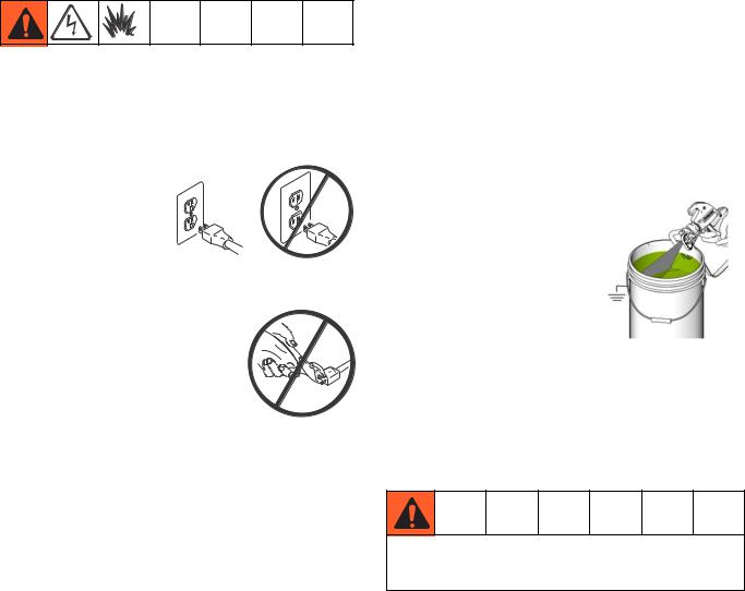
Grounding and Electric
Requirements
Sprayer must be grounded. Grounding reduces the risk of static and electric shock by providing an escape wire for electrical current due to static build up or in the event of a short circuit.
•This sprayer requires a 120 Vac, 60 Hz, 15A circuit with a grounding receptacle.
•Never use an outlet
that is not grounded |
ti5573a |
or an adapter. |
|
•Do not use the sprayer if the electrical cord has a damaged ground prong.
• Only use an extension cord with an undamaged 3-prong plug.
ti5572a
Recommended extension cords for use with this sprayer:
•50 ft (15.0 m) 14 AWG (2.1 mm2)
•100 ft (30.0 m) 12 AWG (3.3 mm2)
Spray gun: ground through connection to a properly grounded fluid hose and pump.
NOTE: Smaller gauge or longer extension cords may reduce sprayer performance.
Fluid supply container: follow local code.
Solvent pails used when flushing: follow local code. Use only conductive metal pails, placed on a grounded surface such as concrete. Do not place the pail on a nonconductive surface, such as paper or cardboard, which interrupts grounding continuity.
Grounding the metal pail: connect a ground wire to the pail by clamping one end to pail and other end to ground such as a water pipe.
Maintaining grounding continuity when flushing or relieving pressure: hold metal part of the spray gun firmly to the side of a grounded metal pail, then trigger the gun.
ti9207a
Thermal Overload
Motor has a thermal overload switch to shut itself down if overheated. If unit overheats, allow approximately 45 minutes for unit to cool. Once cool, switch will close and unit will restart.
To reduce risk of injury from motor starting unexpectedly when it cools, always turn power switch OFF if motor shuts down.
10 |
312667K |
Operation
See Operation manual 312001 for basic information on sprayer set-up, flushing, and storage.
Operation
Pressure Relief Procedure
Follow this Pressure Relief Procedure whenever you stop spraying and before cleaning, checking, servicing, or transporting equipment.
Trigger Lock
Always engage the trigger lock when you stop spraying to prevent the gun from being triggered accidentally by hand or if dropped or bumped.
ti8923a ti8922a
Trigger Locked SG10 Trigger Unlocked SG10
ti8908a |
ti8909a |
Trigger Locked SG20, |
Trigger Unlocked SG20, |
SG2, SG3, SGPro |
SG2, SG3, SGPro |
1. Turn power switch OFF and unplug power cord.
ti2018a
2.Turn Prime/Spray valve to PRIME to relieve pressure.
ti9346a
3.Hold gun firmly to side of pail. Trigger the gun to relieve pressure.
ti9207a
4. Engage trigger lock.
ti8923a ti8908a
SG10 |
SG2, SG3 |
|
SG20, SGPro |
NOTE: Leave Prime/Spray valve in the PRIME position until you are ready to spray again.
If you suspect the spray tip or hose is clogged or that pressure has not been fully relieved after following the steps above, VERY SLOWLY loosen tip guard retaining nut or hose end coupling to relieve pressure gradually, then loosen completely. Clear hose or tip obstruction. Read Unclogging Spray Tip instructions in the Sprayer
or Gun Operation manual.
Pressure Control Knob Settings
ti5597a
High Pressure |
Low Pressure |
Prime/ Rolling |
Spray |
Spray |
Clean |
NOTE: To select function, align symbol on pressure control knob with setting indicator on sprayer.
312667K |
11 |
General Repair Information
General Repair Information
Flammable materials spilled on hot, bare, motor could cause fire or explosion. To reduce risk of burns, fire or explosion, do not operate sprayer with cover removed.
•Keep all screws, nuts, washers, gaskets, and electrical fittings removed during repair procedures. These parts usually are not provided with replacement kits.
•Test repairs after problems are corrected.
•If sprayer does not operate properly, review repair procedure to verify you did it correctly. See Basic Troubleshooting, page 13 and Advanced Troubleshooting, page 18.
•Overspray may build up in the air passages. Remove any overspray and residue from air passages and openings in the enclosures whenever you service sprayer.
•Do not operate the sprayer without the cover in place. Replace if damaged. Covers direct cooling air around motor to prevent overheating.
To reduce risk of serious injury, including electric shock:
•Do not touch moving or electric parts with fingers or tools while testing repair.
•Unplug sprayer when power is not required for testing.
•Install all covers, gaskets, screws and washers before you operate sprayer.
NOTICE
•Do not run sprayer dry for more than 30 seconds. Doing so could damage pump packings.
•Protect the internal drive parts of this sprayer from water. Openings in the cover allow for air cooling of the mechanical parts and electronics inside. If water gets in these openings, the sprayer could malfunction or be permanently damaged.
•Prevent pump corrosion and damage from freezing. Never leave water or water-base paint in sprayer when its not in use in cold weather. Freezing fluids can seriously damage sprayer. Store sprayer with Pump Armor to protect sprayer during storage.
12 |
312667K |

Basic Troubleshooting
Basic Troubleshooting
Check everything in this Basic Troubleshooting table before you bring the sprayer to a Graco/MAGNUM authorized service center.
Problem |
Cause |
Solution |
|
|
|
|
|
|
|
|
|
Power switch is on and sprayer is |
Pressure is set at zero pressure. |
Turn pressure control knob clockwise |
|
plugged in, but motor does not run, |
|
to increase pressure setting. |
|
and pump does not cycle. |
|
|
|
Electric outlet is not providing power. |
• Check that lighted plug on |
||
|
|||
|
|
sprayer is lit (this indicates |
|
|
|
electric power at outlet). |
|
|
|
• Reset building circuit breaker or |
|
|
|
replace fuse. |
|
|
|
|
|
|
Extension cord is damaged. |
Replace extension cord. Read |
|
|
|
Grounding and Electric Require- |
|
|
|
ments, page 10. |
|
|
|
|
|
|
Sprayer electric cord is damaged. |
Check for broken insulation or wires. |
|
|
|
Replace electric cord if damaged. |
|
|
|
|
|
|
Motor or control is damaged. |
Take sprayer to Graco/MAGNUM |
|
|
|
authorized service center. |
|
|
|
|
312667K |
13 |
Basic Troubleshooting
Problem |
Cause |
Solution |
|
|
|
|
|
|
Pump does not prime. |
Prime/Spray Valve is in SPRAY posi- |
Turn Prime/Spray Valve to PRIME |
|
tion. |
position (pointing down). |
|
|
|
|
Inlet screen is clogged or suction |
Clean debris off inlet screen and |
|
tube is not immersed. |
make sure suction tube is immersed |
|
|
in fluid. |
|
|
|
|
Pump was not primed with flushing |
Remove suction tube from paint. |
|
fluid. |
Prime pump with water or |
|
|
solvent-based flushing fluid, see |
|
|
Operation manual 312001. |
|
|
|
|
Inlet valve check ball is stuck. |
Remove suction tube and place a |
|
|
pencil into the inlet section to dis- |
|
|
lodge the ball, allowing pump to |
|
|
prime properly. Or, Power Flush |
|
|
sprayer, see Operation manual |
|
|
312001. |
|
|
|
|
|
AutoPrime may need replacement. |
|
|
Turn power switch ON and listen for |
|
|
“tap” in pump. If you do not hear |
|
|
“tap”, AutoPrime is damaged. Take |
|
|
sprayer to Graco/MAGNUM authorized |
|
|
service center. |
|
|
|
|
Inlet valve check ball or seat is dirty |
Remove inlet fitting. Clean or replace |
|
|
ball and seat. |
|
|
|
|
Outlet valve check ball is stuck. |
ProX7 and ProX9: Insert screw |
|
|
driver in slot and remove |
|
|
Easy-Access door, page 8. Unscrew |
|
|
outlet valve with a 3/4 in. socket. |
|
|
Remove and clean assembly. |
|
|
X5 and X7: Remove outlet fitting and |
|
|
clean outlet check ball. |
|
|
|
|
Suction tube is leaking allowing air to |
Check suction tube for cracks and |
|
enter. |
cuts. Make sure suction tube clamp is |
|
|
on hose. Replace suction tube if |
|
|
cracked or damaged. |
|
|
|
|
Pump valves are worn. |
Check for worn valves, see page 14. |
|
|
|
|
Paint is very thick or sticky. |
Thin material per manufacturer’s |
|
|
instructions. |
|
|
Momentarily turn power switch OFF |
|
|
to allow pump to slow and stop. |
|
|
Repeat as necessary. |
|
|
|
14 |
312667K |
|
|
Basic Troubleshooting |
|
|
|
Problem |
Cause |
Solution |
|
|
|
|
|
|
Pump cycles but does not build up |
Prime/Spray valve in PRIME position |
Turn Prime/Spray valve to SPRAY |
pressure. |
(pointing down). |
position (pointing forward). |
|
|
|
|
Pump is not primed. |
Prime pump, see Operation manual |
|
|
312001. |
|
|
|
|
Inlet screen is clogged or suction |
Clean debris off inlet screen and |
|
tube is not immersed. |
make sure suction tube is immersed |
|
|
in fluid. |
|
|
|
|
Suction tube is leaking, allowing air to |
Check suction tube for cracks and |
|
enter. |
cuts. Make sure suction tube clamp is |
|
|
on hose. Replace suction tube if |
|
|
cracked or damaged. |
|
|
|
|
Prime/Spray Valve is worn or |
Take sprayer to Graco/MAGNUM |
|
obstructed with debris. |
authorized service center. |
|
|
|
|
Pump check ball is stuck. |
Read Pump does not prime section |
|
|
in Troubleshooting, page 14. |
|
|
|
Pump cycles, but paint only dribbles |
Pressure is set too low. |
Slowly turn pressure control knob |
or spurts when spray gun is trig- |
|
clockwise to increase pressure set- |
gered. |
|
ting which will turn motor on to build |
|
|
pressure. |
|
|
|
|
Spray tip is clogged. |
Unclog spray tip, see Operation man- |
|
|
ual 312001. |
|
|
|
|
InstaClean fluid filter is clogged. |
Clean or replace InstaClean fluid fil- |
|
(ProX7 and ProX9 Only) |
ter, see Operation manual 312001. |
|
|
|
|
Spray gun fluid filter is clogged. |
Clean or replace gun fluid filter, see |
|
|
Operation manual 312001. |
|
|
|
|
Spray tip is too large or worn. |
Replace tip. |
|
|
|
312667K |
15 |
Basic Troubleshooting
Problem |
Cause |
Solution |
|
|
|
|
|
|
Pressure is set at maximum but |
Spray tip is clogged. |
Unclog spray tip, see Operation |
cannot achieve a good spray pattern. |
|
manual 312001. |
|
|
|
|
Reversible spray tip is in UNCLOG |
Rotate arrow-shaped handle on |
|
position. |
spray tip so it points forward on gun. |
|
|
|
|
Spray tip is too large for sprayer. |
Select smaller spray tip. |
|
|
|
|
Spray tip is worn beyond capability of |
Replace spray tip. |
|
sprayer. |
|
|
|
|
|
Extension cord is too long or not |
Replace extension cord. See |
|
heavy enough gauge. |
Grounding and Electrical |
|
|
Requirements, page 10. |
|
|
|
|
Spray gun fluid filter is clogged. |
Clean or replace spray gun fluid filter, |
|
|
see Operation manual 312001. |
|
|
|
|
InstaClean fluid filter is clogged. |
Clean or replace InstaClean fluid |
|
(ProX7 and ProX9 Only) |
filter, see Operation manual 312001. |
|
|
|
|
Inlet screen is clogged. |
Clean debris off inlet screen. |
|
|
|
|
Pump valves are worn. |
Check for worn pump valves. |
|
|
a. Prime sprayer with paint |
|
|
b. Trigger gun momentarily. |
|
|
When trigger is released, |
|
|
pump should cycle momen- |
|
|
tarily and stop. If pump con- |
|
|
tinues to cycle, pump valves |
|
|
may be worn. |
|
|
|
|
Material is too thick. |
Thin material. |
|
|
|
|
Hose is too long (if extra section is |
Remove extra section of hose. |
|
added). |
|
|
|
|
Spray gun stopped spraying. Pump is |
Spray tip is clogged. |
Unclog spray tip, see Operation man- |
not cycling. |
|
ual 312001. |
|
|
|
When paint is sprayed, it runs down |
Coat is going on too thick. |
Move gun faster. |
the wall or sags. |
|
|
|
Choose a tip with smaller hole size. |
|
|
|
|
|
|
|
|
|
Choose tip with wider fan. |
|
|
|
|
|
Make sure gun is far enough from |
|
|
surface. |
|
|
|
When paint is sprayed, coverage is |
Coat is going on too thin. |
Move gun slower. |
inadequate. |
|
|
|
Choose tip with larger hole size. |
|
|
|
|
|
|
|
|
|
Choose tip with narrower fan. |
|
|
|
|
|
Make sure gun is close enough to |
|
|
surface. |
|
|
|
16 |
312667K |
Loading...