


INSTRUCTIONS-PARTS LIST |
307±760 |
|
This manual contains IMPORTANT |
Rev G |
|
INSTRUCTIONS and WARNINGS. |
Supersedes E |
|
READ AND RETAIN FOR REFERENCE. |
||
|
||
50 Hz, 220/240 Volts, 0.5 Amp |
|
|
PT2000 Pressure Roller System |
|
17.5 bar (250 psi) MAXIMUM WORKING PRESSURE
Model 220±240, Series E
Complete System
with hose, roller valve, extension and roller
Model 221±076,
Basic System without hose,
PATENT NO,
COPYRIGHT 1986, GRACO INC.

TABLE OF CONTENTS
Terms . . . . . . . . . . . . . . . . . . . . . . . . . . . . . . . . . . . . . . . . . . . . . . 2
Warnings . . . . . . . . . . . . . . . . . . . . . . . . . . . . . . . . . . . . . . . . . . . 2
PT2000 Pressure Roller System Description . . . . . . . . . . . . 3
Setup . . . . . . . . . . . . . . . . . . . . . . . . . . . . . . . . . . . . . . . . . . . . . . 4
Startup . . . . . . . . . . . . . . . . . . . . . . . . . . . . . . . . . . . . . . . . . . . . . 5
Operation . . . . . . . . . . . . . . . . . . . . . . . . . . . . . . . . . . . . . . . . . . 5
Maintenance
Flushing . . . . . . . . . . . . . . . . . . . . . . . . . . . . . . . . . . . . . . . . 6
Installing & Removing a Roller Cover . . . . . . . . . . . . . . . 7
Cleaning the Roller Diffuser . . . . . . . . . . . . . . . . . . . . . . . 7
Troubleshooting Chart . . . . . . . . . . . . . . . . . . . . . . . . . . . . . . . 8
Repair
Roller Valve . . . . . . . . . . . . . . . . . . . . . . . . . . . . . . . . . . . . 9
Fuse . . . . . . . . . . . . . . . . . . . . . . . . . . . . . . . . . . . . . . . . . . 10
ON/OFF Switch . . . . . . . . . . . . . . . . . . . . . . . . . . . . . . . . 10
Rectifier . . . . . . . . . . . . . . . . . . . . . . . . . . . . . . . . . . . . . . . 10
Power Supply Cord . . . . . . . . . . . . . . . . . . . . . . . . . . . . . 10
Pressure Switch . . . . . . . . . . . . . . . . . . . . . . . . . . . . . . . . 11
Outlet Valve . . . . . . . . . . . . . . . . . . . . . . . . . . . . . . . . . . . 11
Inlet Valve . . . . . . . . . . . . . . . . . . . . . . . . . . . . . . . . . . . . . 11
Diaphragm . . . . . . . . . . . . . . . . . . . . . . . . . . . . . . . . . . . . 12
Suction Tube . . . . . . . . . . . . . . . . . . . . . . . . . . . . . . . . . . 12
Priming Valve & Tube . . . . . . . . . . . . . . . . . . . . . . . . . . . 12
Motor, Connecting Rod & Bearing . . . . . . . . . . . . . . . . . 13
Parts Drawing & Lists . . . . . . . . . . . . . . . . . . . . . . . . . . . . . . . 14
Accessories . . . . . . . . . . . . . . . . . . . . . . . . . . . . . . . . . . . . . . . 18
Technical Data . . . . . . . . . . . . . . . . . . . . . . . . . . . . . Back Cover
Warranty . . . . . . . . . . . . . . . . . . . . . . . . . . . . . . . . . . Back Cover
TERMS
Be sure you read and understand each of these terms before reading the rest of the manual.
WARNING Alerts user to avoid or correct conditions which could cause serious bodily injury.
CAUTION Alerts user to avoid or correct conditions which could damage or destroy the equipment.
NOTE Gives additional explanation or helpful hints.
WARNING
Be sure all operators of this equipment read, understand, and follow the warnings and instructions in this manual!
GENERAL SAFETY
Use extreme care not to splash paint, contaminated flushing water or solvent into your eyes. Wear protective eyewear.
Be sure the area in which you are working is extremely well-ventilated, to avoid a buildup of harmful paint fumes.
EQUIPMENT MISUSE HAZ-
ARD
This system is designed for be used at 17.5 bar (250 psi) Maximum Working Pressure. Use only components and accessories which are designed for use with the PT2000 System.
To reduce the risk of electric shock, do not expose the system to rain. Always store the system indoors. Do not operate the pump with the pump base cover removed.
ELECTRICAL GROUNDING
Electrical grounding is essential to reduce the risk of an electric shock or other serious bodily injury from static sparking. Read and follow the grounding instructions on page 4 of this manual.
EXTENSION MISUSE HAZARD
THIS IS NOT AN AIRLESS GUN EXTENSION (for example, pole gun). Do not attempt to modify the extension or roller frame, or to use parts which are not designed for use with this system.
Improper use of the extension, roller frame, hose or roller valve can result in component rupture or explosion and cause serious bodily injury.
AVOID POWER LINES
Avoid contacting any power lines with the extension. Contact with power lines could cause extremely serious bodily injury, including burns or electrocution.
307±760
Any misuse of this equipment, such as modifying parts, using incompatible paint or solvent, or using worn or damaged parts, can cause the equipment to rupture and result in serious bodily injury, fire or explosion, and property damage.
Never alter or modify any part of this equipment; doing so could cause it to overpressurize or malfunction.
Check all parts of the system regularly and repair or replace any worn or damaged parts immediately.
HAZARD OF USING FLUIDS CONTAINING HALOGENATED HYDROCARBONS
Never use 1, 1, 1-trichloroethane, methylene chloride, other halogenated hydrocarbon solvents or fluids containing such solvents in this equipment. Such use could result in a serious chemical reaction, with the possibility of explosion, which could cause death, serious bodily injury and/or substantial property damage.
Consult your fluid suppliers to ensure that the fluids being used are compatible with aluminum and zinc parts.

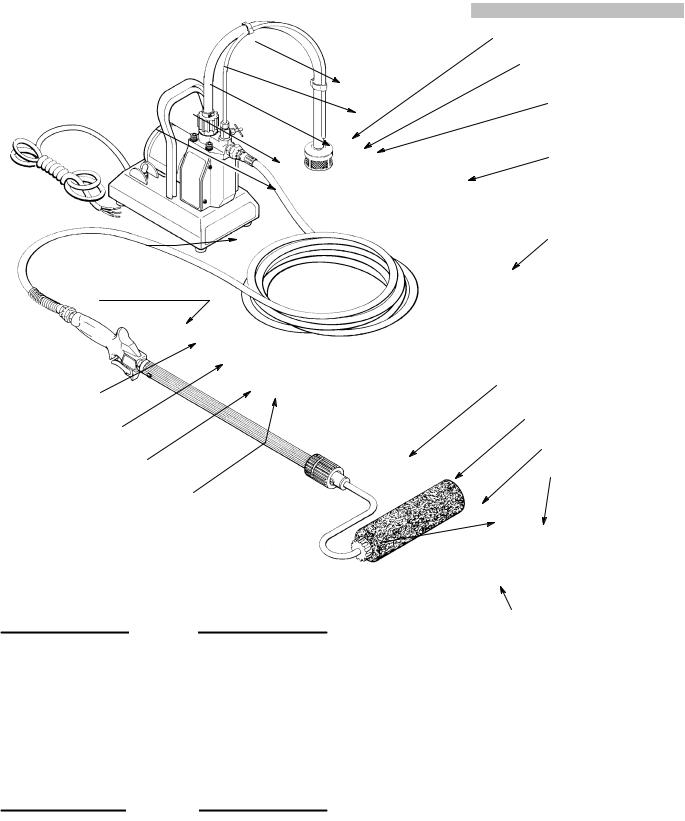
PT2000 PRESSURE ROLLER SYSTEM DESCRIPTION
SUCTION TUBE
PRIMING TUBE
INLET VALVE
MOTOR
ON/OFF
SWITCH
POWER SUPPL
Add plug
SPRING GUARD
MUST BE AT
THIS END
ROLLER VALVE
Fig 1
Motor
The motor moves the
Pressure
The pressure on and off to
Diaphragm
The diaphragm connecting phragm draws the outlet valve
Priming Valve
The priming valve assists in priming the pump during startup. Turning the priming valve counterclockwise causes the paint to drain directly back into the pail through the priming tube. Turning the knob clockwise causes the paint to flow through the fluid outlet valve and to the hose, roller valve and extension.
Outlet Valve
The outlet valve has a ball check which prevents paint from flowing backwards into the pump. This helps keep an even supply of paint to the roller each time you trigger the roller valve.
Inlet Valve
As the diaphragm draws paint from the suction tube the paint passes through the inlet valve which opens to allow paint into the pump.
PRIMING VALVE
PAINT STRAINER
7.6 M (25 FT) HOSE
460 TO 920 MM (18 TO 36 IN.) TELESCOPING EXTENSION
LOCKNUT
ROLLER FRAME
12 MM (1/2 IN.) NAP ROLLER COVER
The hose has swivel±type couplings for easy assembly. A larger diameter outlet hose and chemical-resistant outlet and suction hoses are available. See ACCESSORIES on page 17.
Roller Valve
The roller valve controls paint flow to the roller by triggering it on and off.
Pressure Roller
The pressure roller has a telescoping extension and a roller cover for use on smooth surfaces. Longer extensions and different types of roller covers are available. See the ACCESSORIES on page 17.
307±760 3
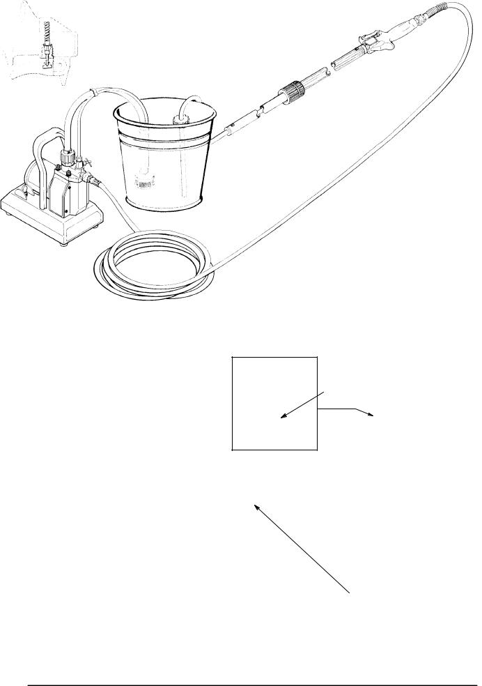
SETUP
ON/OFF
SWITCH
POWER SUPPLY CORD Add plug according to local code
SPRING GUARD
MUST BE AT
THIS END
USE TWO
WRENCHES
TO TIGHTEN
ROLLER VALVE
TRIGGER
USE TWO
WRENCHES
TO TIGHTEN
ROLLER FRAME Apply PTFERtape
to male threads
Y WITH
PRIMING VALVE
PAINT STRAINER
7.6 M (25 FT) HOSE
460 TO 920 MM (18 TO 36 IN.) TELESCOPING EXTENSION
LOCKNUT
HAND TIGHTEN ONLY
 12 MM (1/2 IN.) NAP
ROLLER COVER
|
|
|
|
HAND TIGHTEN ONLY |
|
|
|
|
|
|||
Fig 2 |
to avoid cracking roller cover |
|
|
|
|
|
||||||
|
|
|
|
|
||||||||
|
|
|
|
|
|
|
|
|
||||
|
|
CAUTION |
|
1. Assemble the system as shown in Fig 2, following the |
|
|||||||
|
|
|
||||||||||
To avoid premature wear of the pressure switch, |
|
notes on the drawing. |
|
|
|
|||||||
never use more than 7.6 m (25 ft) of 1/4 in. ID outlet |
2. Prepare the paint according to the manufacturer's |
|||||||||||
hose. When longer outlet hose is needed, use 3/8 |
||||||||||||
|
recommendations. Remove any skin from the top of |
|||||||||||
in. ID hose at a maximum of 30 m (100 ft) long. Nev- |
|
|||||||||||
|
the paint. Strain the paint. Thin the paint as needed. |
|||||||||||
er use 1/4 in. ID and 3/8 in. ID hose together. |
|
|
||||||||||
|
|
|
|
|
|
|
|
|
||||
See ACCESSORIES, page 17, for ordering optional |
3. Be sure the electrical service is properly rated for |
|||||||||||
|
your sprayer and that the outlet you use is properly |
|||||||||||
hoses. |
|
|
||||||||||
|
|
grounded. Install an appropriate plug on the power |
||||||||||
|
|
|
|
|
||||||||
|
|
|
|
|
supply cord, according to your local electrical code. |
|||||||
|
|
|
|
|
Do not use an adapter. All extension cords must have |
|||||||
|
|
WARNING |
|
|
three wires. Use the chart below for selecting the ap- |
|||||||
|
|
|
|
propriate wire gauge for the extension cord. |
||||||||
|
|
|
|
|||||||||
|
|
|
|
|
||||||||
|
Never remove the grounding pin of the power sup- |
|
|
|
|
|
|
|
|
|||
|
ply cord plug. Be sure the outlet is properly |
|
|
|
|
|
|
|
|
|||
|
|
|
|
Extension Cord Chart |
|
|
||||||
|
grounded. In the event of an electrical short circuit, |
|
|
|
|
|
|
|
|
|||
|
|
Cord Length |
Extension Cord |
|
|
|||||||
|
grounding reduces the risk of an electric shock by |
|
|
|
||||||||
|
|
meters |
feet |
Cross Sectional Area |
|
|
||||||
|
providing an escape wire for the electric current. |
|
|
|
|
|||||||
|
|
|
|
|
|
|
|
|
|
|||
|
Inspect the power supply cord and extension cord |
|
1 ± 30 |
|
1 ± 100 |
|
0.75 mm2 |
|
|
|||
|
|
30 ± 61 |
|
100 ± 200 |
|
1.0 mm2 |
|
|
||||
|
before each use. Be sure they are in good condition |
|
61 ± 92 |
|
200 ± 300 |
|
1.5 mm2 |
|
|
|||
|
and have undamaged three-pin plugs. Replace |
4. Loosen the locknut on the telescoping extension and |
||||||||||
|
immediately if either cord is worn or damaged. |
|
||||||||||
|
|
|
adjust the extension to the desired length. Firmly |
|||||||||
|
|
|
|
|
||||||||
4 |
307±760 |
|
|
tighten the locknut. |
|
|
|
|||||
|
|
|
|
|
|
|
|
|
||||
STARTUP
1.Place the suction tube in the pail of paint.
2.Plug in the sprayer.
3.Open the priming valve 2 turns counterclockwise.
4.Turn the ON/OFF switch ON.
5.You can see the paint being drawn into the suction tube (if the tube is clean). As soon as you see paint flow through the priming tube, close the priming valve. This usually takes less than 30 seconds.
CAUTION
Failure to completely close the priming valve after the system is primed will cause the valve to erode, greatly shortening the valve life.
NOTE: If your system is hard to prime, first try to force feed the suction tube. Hold the suction tube in a vertical position and pour paint into it. Turn on the system. If the system does not prime within one minute, shut it off. Heavy viscosity paint may need to be thinned. Be sure to follow the paint manufacturer's recommendations on thinning.
6.When the outlet hose and extension tube are fully primed, the motor will run when there is paint demand, but appears to shut itself off when there is no paint demand.
NOTE: An occasional start and stop of the motor when the roller valve is not triggered is normal.
OPERATION
WARNING
To reduce the risk of electric shock, do not expose the system to rain. Always store the system indoors.
CAUTION
Always allow cold equipment to warm to room temperature before using to prevent damaging the system. Always store the system indoors.
CAUTION
Do not use lacquer or lacquer thinner in the suction and outlet hoses supplied with this system. These fluids quickly destroy the hose material. Use the optional chemical±resistant hoses.
See ACCESSORIES, page 17, for ordering optional hoses.
1.With the system fully primed, trigger the roller valve briefly until paint comes to the roller.
2.Experiment with triggering and rolling the paint until you determine just how often you need to trigger the roller valve to keep an even flow of paint to the roller.
3.To adjust the extension tube length, loosen the locknut and extend or retract the tube. If retracting, some paint in the tube will be pushed out to the roller. Roll this excess paint onto the wall, or completely retract the tube, drain the excess paint into a pail, and then adjust the tube length. Tighten the locknut securely.
4.Whenever you stop painting, turn the ON/OFF switch to OFF and trigger the roller valve. Elevate the roller end of the tube to prevent paint from draining out the roller end.
5.Flush the system thoroughly and immediately after each use to keep it in good working order. See page 6.
307±760 5
MAINTENANCE
CAUTION
Thorough flushing and proper maintenance are essential to keep your system working properly
Improper flushing or maintenance may prevent the system from working the next time you need it, and may result in costly damage to the system.
ALWAYS flush your system thoroughly and immediately after each use.
ALWAYS fully extend the telescoping extension when flushing to clean it thoroughly.
ALWAYS drain all water out of the roller valve and extension and leave the system filled with mineral spirits to prevent corrosion.
Flushing (Latex Paint Only)
1.Turn the ON/OFF switch to OFF.
2.Fully extend the telescoping extension.
3.Trigger the roller valve and roll out the excess paint onto a wall or newspaper. Remove the roller cover and diffuser, and soak in a pail of warm soapy water.
4.Place the suction tube in the pail of warm, soapy water. Hold the roller frame over the paint pail, turn on the system and trigger the roller valve to drain and save the paint in the hoses. Release the trigger and shut off the pump as soon as all paint is drained, to avoid contaminating the paint with the flushing water.
5.Now hold the roller frame over the flushing pail. Turn on the pump and trigger the roller valve. Circulate the
6.Raise the suction tube above the water and run the pump for a few seconds to drain the flushing solution. Shut off the pump.
7.Wash off all external parts of the hoses, extension, roller frame, roller valve and pump.
8.Using clean, clear water, flush again, changing water as often as necessary, until the system is thoroughly cleaned.
9.Finally, flush the system with clean mineral spirits for just a few seconds. Open the priming valve and turn off the pump. Some mineral spirits must be left in the system to prevent corrosion. Retract the extension before storing it.
CAUTION
Never leave water or water-based paint (latex) in the system. To prevent corrosion in the pump, extension, roller valve and roller frame, your final flush must be mineral spirits.
10.Clean the roller cover thoroughly by rinsing it inside and out. Clean the diffuser as explained on page 3.
11.Oil the needle in the roller valve and trigger the valve a few times to distribute the oil. See Detail A, Fig 3.
Flushing (Oil±based Paint Only)
NOTE: Follow the instructions above, except use mineral spirits. Do not heat the mineral spirits.
OIL REGULARLY
EXTENSION MUST BE FULLY EXTENDED WHEN FLUSHING
6307±760
 Loading...