


 Loading...
Instructions - Parts
Automatic Airless |
|
Spray Guns |
311053E |
Part No. 288048
For airless spraying of paints and coatings.
Part No. 288554
For sealant streaming applications.
4000 psi (28 MPa, 280 bar) Maximum Working Fluid Pressure
Mounting manifolds must be ordered separately. Refer to Parts section.
Important Safety Instructions
Read all warnings and instructions in this manual.
Save these instructions.
Model 288048 Shown |
TI8089a |
|
|
II 2 G c T6

Related Manuals
Contents
Related Manuals . . . . . . . . . . . . . . . . . . . . . . . . . . . 2
Warnings . . . . . . . . . . . . . . . . . . . . . . . . . . . . . . . . . 3
Installation . . . . . . . . . . . . . . . . . . . . . . . . . . . . . . . . 5
Ventilate Spray Booth . . . . . . . . . . . . . . . . . . . . . 5
Configure Gun and Manifold . . . . . . . . . . . . . . . . 5
Install Air Fittings . . . . . . . . . . . . . . . . . . . . . . . . . 6
Ground System . . . . . . . . . . . . . . . . . . . . . . . . . . 6
Mount Gun . . . . . . . . . . . . . . . . . . . . . . . . . . . . . 7
Setup . . . . . . . . . . . . . . . . . . . . . . . . . . . . . . . . . . . . . 8
Air Line and Accessory Recommendations . . . . 8
Fluid Line and Accessory Recommendations . . . 8
Flush Spray Gun . . . . . . . . . . . . . . . . . . . . . . . . 10
Install Spray Tip . . . . . . . . . . . . . . . . . . . . . . . . 10
Adjust Spray Pattern . . . . . . . . . . . . . . . . . . . . . 10
Adjust a Streaming Tip . . . . . . . . . . . . . . . . . . . 10
Operation . . . . . . . . . . . . . . . . . . . . . . . . . . . . . . . . 11
Pressure Relief Procedure . . . . . . . . . . . . . . . . 11
Apply the Fluid . . . . . . . . . . . . . . . . . . . . . . . . . 11
Daily Gun Care . . . . . . . . . . . . . . . . . . . . . . . . . . . . 12
General System Maintenance . . . . . . . . . . . . . . 13
Daily Cleaning Procedure . . . . . . . . . . . . . . . . . 13
Daily Flushing Procedure . . . . . . . . . . . . . . . . . 13
Related Manuals
Troubleshooting . . . . . . . . . . . . . . . . . . . . . . . . . . . 14
General Troubleshooting . . . . . . . . . . . . . . . . . . 14
Spray Pattern Troubleshooting . . . . . . . . . . . . . 16
Service . . . . . . . . . . . . . . . . . . . . . . . . . . . . . . . . . . 17
Disassembly . . . . . . . . . . . . . . . . . . . . . . . . . . . 17
Reassembly . . . . . . . . . . . . . . . . . . . . . . . . . . . . 19
Parts . . . . . . . . . . . . . . . . . . . . . . . . . . . . . . . . . . . . 20
GG0 Series Tip Selection Charts . . . . . . . . . . . . . 24
Sealer Application Tip and Air Cap
Selection Charts . . . . . . . . . . . . . . . . . . . . . . . . . . . 25
Shower Tip . . . . . . . . . . . . . . . . . . . . . . . . . . . . 25
Streaming Tips . . . . . . . . . . . . . . . . . . . . . . . . . 25
Single Orifice Fan Pattern Spray Tips . . . . . . . . 25
Accessories . . . . . . . . . . . . . . . . . . . . . . . . . . . . . . 26
Dimensions . . . . . . . . . . . . . . . . . . . . . . . . . . . . . . . 27
Mounting Hole Layout . . . . . . . . . . . . . . . . . . . . . . 28
Technical Data . . . . . . . . . . . . . . . . . . . . . . . . . . . . 29
Graco Standard Warranty . . . . . . . . . . . . . . . . . . . 30
Graco Information . . . . . . . . . . . . . . . . . . . . . . . . . 30
The Automatic Airless Spray Guns manual is available in the following languages. See the following chart for specific language and part number.
Manual |
Language |
|
|
311053 |
English |
|
|
311665 |
Chinese |
|
|
311666 |
Danish |
|
|
311667 |
Dutch |
|
|
311668 |
Finnish |
|
|
311669 |
French |
|
|
311670 |
German |
|
|
311671 |
Italian |
|
|
Manual |
Language |
|
|
311672 |
Japanese |
|
|
311673 |
Korean |
|
|
311674 |
Norwegian |
|
|
311675 |
Polish |
|
|
311676 |
Russian |
|
|
311677 |
Spanish |
|
|
311678 |
Swedish |
|
|
2 |
311053E |

Warnings
Warnings
The following warnings are for the setup, use, grounding, maintenance, and repair of this equipment. The exclamation point symbol alerts you to a general warning and the hazard symbol refers to procedure-specific risk. Refer back to these warnings. Additional, product-specific warnings may be found throughout the body of this manual where applicable.
 WARNING
EQUIPMENT MISUSE HAZARD
Misuse can cause death or serious injury.
•Do not operate the unit when fatigued or under the influence of drugs or alcohol.
•Do not exceed the maximum working pressure or temperature rating of the lowest rated system component. See Technical Data in all equipment manuals.
•Use fluids and solvents that are compatible with equipment wetted parts. See Technical Data in all equipment manuals. Read fluid and solvent manufacturer’s warnings. For complete information about your material, request MSDS forms from distributor or retailer.
•Check equipment daily. Repair or replace worn or damaged parts immediately with genuine manufacturer’s replacement parts only.
•Do not alter or modify equipment.
•Use equipment only for its intended purpose. Call your distributor for information.
•Route hoses and cables away from traffic areas, sharp edges, moving parts, and hot surfaces.
•Do not kink or over bend hoses or use hoses to pull equipment.
•Keep children and animals away from work area.
•Comply with all applicable safety regulations.
SKIN INJECTION HAZARD
High-pressure fluid from gun, hose leaks, or ruptured components will pierce skin. This may look like just a cut, but it is a serious injury that can result in amputation. Get immediate surgical treatment.
•Do not point gun at anyone or at any part of the body.
• Do not put your hand over the spray tip.
•Do not stop or deflect leaks with your hand, body, glove, or rag.
•Follow Pressure Relief Procedure in this manual, when you stop spraying and before cleaning, checking, or servicing equipment.
FIRE AND EXPLOSION HAZARD
Flammable fumes, such as solvent and paint fumes, in work area can ignite or explode. To help prevent fire and explosion:
• Use equipment only in well ventilated area.
• Eliminate all ignition sources; such as pilot lights, cigarettes, portable electric lamps, and plastic drop cloths (potential static arc).
• Keep work area free of debris, including solvent, rags and gasoline.
•Do not plug or unplug power cords, or turn power or light switches on or off when flammable fumes are present.
•Ground all equipment in the work area. See Grounding instructions.
•Use only grounded hoses.
•Hold gun firmly to side of grounded pail when triggering into pail.
•If there is static sparking or you feel a shock, stop operation immediately. Do not use equipment until you identify and correct the problem.
•Keep a working fire extinguisher in the work area.
311053E |
3 |

Warnings
 WARNING
PRESSURIZED EQUIPMENT HAZARD
Fluid from the gun/dispense valve, leaks, or ruptured components can splash in the eyes or on skin and cause serious injury.
•Follow Pressure Relief Procedure in this manual, when you stop spraying and before cleaning, checking, or servicing equipment.
•Tighten all fluid connections before operating the equipment.
•Check hoses, tubes, and couplings daily. Replace worn or damaged parts immediately.
TOXIC FLUID OR FUMES HAZARD
Toxic fluids or fumes can cause serious injury or death if splashed in the eyes or on skin, inhaled, or swallowed.
•Read MSDS’s to know the specific hazards of the fluids you are using.
•Store hazardous fluid in approved containers, and dispose of it according to applicable guidelines.
PERSONAL PROTECTIVE EQUIPMENT
You must wear appropriate protective equipment when operating, servicing, or when in the operating area of the equipment to help protect you from serious injury, including eye injury, inhalation of toxic fumes, burns, and hearing loss. This equipment includes but is not limited to:
•Protective eyewear
•Clothing and respirator as recommended by the fluid and solvent manufacturer
•Gloves
•Hearing protection
4 |
311053E |
Installation
Ventilate Spray Booth
Check and follow all National, State, and Local  codes regarding air exhaust velocity requirements.
Check and follow all local safety and fire codes.
Configure Gun and Manifold
(Order manifold separately. See Accessories, page 26.)
Manifolds 241161 and 241162
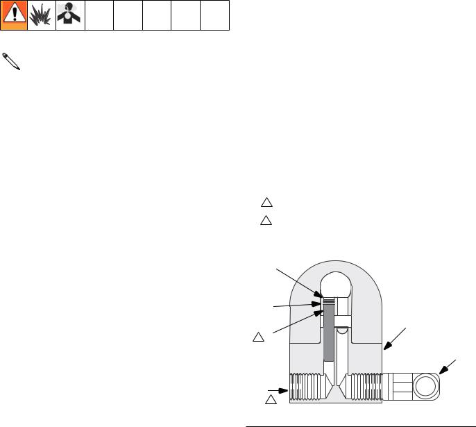
The gun is supplied with an internal fluid plug (4). See FIG. 1. To use the gun in a circulating system, remove the internal plug. In a non-circulating system, leave the plug in place to minimize flush time.
Installation
Non-circulating System:
1.Apply anti-seize lubricant 222955 to the threads and mating faces of manifold (102), plug (109), and elbow (107), supplied unassembled.
2.Install an elbow (107) in one fluid port of the manifold (102), and a plug (109) in the other port.
3.Install the internal plug (4) in the gun fluid port on the same side as the manifold plug.
4.Connect the fluid supply line to the manifold elbow (107). See FIG. 1.
5.Install the gun on the manifold, using the four screws (14). Start the threads of all four screws, and tighten the front two screws first, and then tighten the back two screws to 65 in-lb (7.3 N•m).
1 Remove when used in circulating systems.
2Replace with an elbow (107) when used in circulating systems.
Circulating System
1.Apply anti-seize lubricant 222955 to the threads and mating faces of the manifold (102) and the elbows (107), supplied unassembled.
2.Install the elbows (107) in both fluid ports of the manifold (102).
3.Connect the fluid supply line to one elbow and the fluid return line to the other. The manifold fluid ports are reversible.
5
6 |
102
1 4
107
109
TI8587b
2
FIG. 1: Non-Circulating Setup (Cutaway View)
311053E |
5 |
Installation
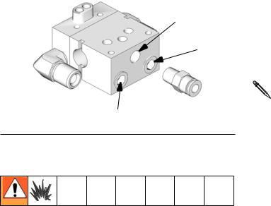
Install Air Fittings
1.Install 1/4 in. tube fitting into the cylinder (CYL) air port.
2.Install plugs into the atomization (ATOM) air port and the fan (FAN) air port.
CYL
ATOM
FAN |
TI8225a |
|
FIG. 2: Air Fittings
Ground System
The following grounding instructions are minimum requirements for a system. Your system may include other equipment or objects that must be grounded. Check your local electrical code for detailed grounding instructions for your area and type of equipment. Your system must be connected to a true earth ground.
Ground Pump
Ground the pump by connecting a ground wire and clamp between the fluid supply and a true earth ground as instructed in your separate pump instruction manual.
Ground Air Compressors and Hydraulic
Power Supplies
Ground them according to the manufacturer recommendations.
Ground Air, Fluid, and Hydraulic Hoses Connected to Pump
Use only electrically conductive hoses with a maximum of 100 ft (30.5 m) combined hose length to ensure grounding continuity. Check the electrical resistance of your air and fluid hoses at least once a week. If the total resistance to ground exceeds 25 megohms, replace the hose immediately.
Use a meter that is capable of measuring resis-  tance at this level.
Ground Spray Gun
Ground the spray gun by connecting it to a properly grounded fluid hose and pump.
Ground Fluid Supply Container
Ground the fluid supply container according to local code.
Ground Object Being Sprayed
Ground the object being sprayed according to local code.
Ground Solvent Pails
Ground all solvent pails that are used with flushing according to local code. Use only metal pails, which are conductive. Do not place the pail on a non-conductive surface, such as paper or cardboard, which interrupts the grounding continuity.
6 |
311053E |
Mount Gun
Reciprocating Arm Rod Mount
Manifolds 241161 and 241162
To mount the gun on a reciprocating arm rod [0.5 in. (13 mm) diameter maximum]:
1.Insert the mounting bar (A) through the hole in the manifold as shown in FIG. 3.
Use the 1/8 in. alignment pin (P) to assist in  orienting the gun.
2.Secure the gun to the bar by tightening the mounting screw (B).
3.Ensure the tip of the gun is 8 to 10 in. (150 to 200 mm) from the surface of the object being sprayed.
B
P
A
TI8111a
FIG. 3: Reciprocating Arm Mount
Installation
Stationary Support Mount
All Manifolds
To mount the gun on a stationary support (refer to FIG. 4. and Mounting Hole Layout, page 28):
1.Attach the gun to the support with two M5 x 0.8 capscrews (C). The screws must be long enough to engage the threaded holes in the gun manifold to a depth of 1/4 in. (6 mm).
2.Ensure the tip of the gun is 8 to 10 in. (150 to 200 mm) from the surface of the object being sprayed.
C |
TI8112a |
|
FIG. 4: Stationary Support Mount
311053E |
7 |
Setup
Setup
Air Line and Accessory |
Fluid Line and Accessory |
Recommendations |
Recommendations |
1.Install an air pressure regulator on the gun cylinder air supply line.
A minimum of 70 psi (0.49 MPa, 4.9 bar) air pressure must be supplied to the cylinder for proper operation. Air pressure opens the valve, a spring closes the valve. A three-way air valve, which exhausts cylinder air, is required.
2.Install a bleed-type air shutoff valve on the main air line. Install an additional bleed-type valve on each pump air supply line, downstream of the pump air regulator, to relieve air trapped between this valve and the pump after the air regulator is shut off.
The bleed-type air shutoff valve is required in your system to relieve air trapped between this valve and the pump after the air regulator is closed. Trapped air can cause the pump to cycle unexpectedly, which could result in serious injury.
3.Install a bleed-type air shutoff valve on the gun air cylinder supply line, downstream of the air regulator, to shut off air to the gun cylinder. Connect the air supply line to the gun cylinder air inlet (C). See Fig. 4.
The cylinder air inlet accepts 1/4 in. (6.3 mm) O.D.  tubing.
•A fluid drain valve(s) is required in your system to assist in relieving fluid pressure in the displacement pump, hose and gun; triggering the gun to relieve pressure may not be sufficient.
•A fluid pressure regulator must be installed in the system if the pump's maximum working pressure exceeds the gun's maximum fluid working pressure (see the front cover).
1.Install a fluid filter and drain valve(s) close to the pump's fluid outlet.
2.Install a fluid pressure regulator to control fluid pressure to the gun.
Some applications require fine-tuned control of fluid  pressure. You can control fluid pressure more accurately with a fluid pressure regulator than by regulating the air pressure to the pump.
3.Install a fluid shutoff valve to shut off the fluid supply to the gun.
4.For paint spray applications, install an in-line fluid filter, part no. 210500, on the gun fluid inlet (F) to avoid clogging the spray tip with particles from the fluid. See Fig. 4.
5.Connect the electrically conductive fluid hose to the gun fluid inlet (F) or optional in-line filter.
8 |
311053E |

Setup
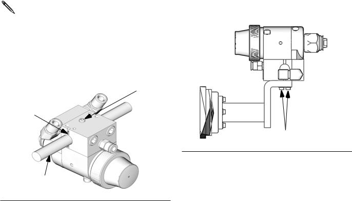
Manifolds 288219 and 288220 |
Manifold 244930 |
6.In a circulating system, connect an electrically conductive fluid hose to the gun fluid outlet (G).
In a non-circulating system, remove the gun fluid outlet fitting (G) and plug the outlet port with the pipe plug (109) supplied.
KEY
C Cylinder Air Inlet: accepts 1/4 in. (6.3 mm) O.D. tubing F Fluid Inlet: 1/4-18 nptf or #5 JIC (1/2-20 unf)
G Fluid Outlet (circulating gun only): 1/4-18 nptf or #5 JIC (1/2-20 unf)
G (or F)
C
F (or G)
FAN ATOM
CYL
TI8113a
FIG. 5
7.This manifold is equipped with passages for circulating water to maintain the temperature of the gun. Ports provided are:
•Side water inlet, 1/4 npt(f)
•Top water outlets, 1/8 npt(f)
•Side RTD sensor, 1/8 npt(f)
See Accessories, page 26, for available fittings and sensors.
KEY
L Water Outlet: 1/8 npt(f)
M Air Inlet (to open valve): 1/8 npt(f)
N Fluid Inlet: 3/8(f)
P Water Inlet: 1/4 npt(f)
M
L
N
L
TI8115a
P TI8116a
FIG. 6
311053E |
9 |
Loading...