

Gorenje Aerogor ECO COMPACT INVERTER 13A, Aerogor ECO COMPACT INVERTER 10A, Aerogor ECO Inverter 13 A, Aerogor ECO Inverter 10 A, Aerogor POWER EVI Inverter 18 A Installation Manual
...
www.gorenje.com
V 2.0
Aerogor ECO Inverter 10A/13A
Aerogor ECO COMPACT Inverter 10A/13A
Aerogor POWER EVI Inverter 15A/18A
INSTALLATION MANUAL


TABLE OF CONTENTS
1 BEFORE USE ................................................................................................................ 1
1.1 WARNINGS ............................................................................................................ 1
1.2 DISPOSAL .............................................................................................................. 3
1.3 HEATING SYSTEM REQUIREMENTS (MANDATORY) ......................................... 3
1.4 INCLUDED IN THE PACKAGE ............................................................................... 4
1.5 TECHNICAL TABLE ................................................................................................ 5
1.5.1 AEROGOR ECO COMPACT INVERTER 10A, 13A ......................................... 5
1.5.2 AEROGOR ECO INVERTER 10A, 13A ............................................................ 6
1.5.3 AEROGOR POWER EVI INVERTER 15A, 18A ............................................... 7
1.6 DIMENSIONS ......................................................................................................... 8
1.6.1 INDOOR UNITS ............................................................................................... 8
1.6.2 OUTDOOR UNITS ........................................................................................... 9
1.7 OPERATING RANGE ............................................................................................10
1.8 WORKING PRINCIPLE ..........................................................................................11
1.9 MAIN COMPONENTS ............................................................................................12
1.9.1 INDOOR UNITS ..............................................................................................12
1.9.2 OUTDOOR UNITS ..........................................................................................14
1.9.3 AEROGOR POWER EVI INVERTER 15A/ 18A ..............................................16
2 INSTALLATION .............................................................................................................17
2.1 INSTALLATION OF THE INDOOR UNIT ...............................................................17
2.2 INSTALLATION OF THE OUTDOOR UNIT............................................................18
2.3 FOUNDATION .......................................................................................................20
2.3.1 INSTALLATION OF C PROFILE AND LEGS ..................................................21
2.4 INSTALATION OF THE REFRIGERANT SYSTEM (SPLIT TYPE) .........................22
2.4.1 Height difference between indoor and outdoor unit .........................................24
2.5 INSTALATION OF HYDRAULIC CONNECTIONS (COMPACT TYPE) ..................26
3 ELECTRICAL WIRING ..................................................................................................27
3.1 AEROGOR ECO INVERTER 10A, 13A AND AEROGOR POWER EVI INVERTER
15A, 18A ...........................................................................................................................27
3.1.1 INDOOR UNIT ................................................................................................27
3.1.2 TEMPERATURE SENSORS ...........................................................................28
3.1.3 CONNECTION BETWEEN INDOOR AND OUTDOOR UNIT ..........................29
3.2 AEROGOR ECO COMPACT INVERTER 10A, 13A ...............................................30
3.2.1 INDOOR UNIT ................................................................................................30

3.2.2 TEMPERATURE SENSORS ...........................................................................31
3.2.3 CONNECTION BETWEEN INDOOR AND OUTDOOR UNIT ..........................32
4 CONTROL UNIT ...........................................................................................................33
4.1 DESCRIPTION OF SYMBOLS ON THE CONTROL UNIT .....................................33
4.2 DESCRIPTION OF THE TEMPERATURES ON THE CONTROL UNIT .................36
5 QUICK SETTINGS ........................................................................................................37
5.1 PARALLEL MOVE OF THE HEATING CURVE ......................................................37
5.1.1 SETTING THE PARALLEL MOVE OF THE HEATING CURVE – HEATING
CIRCUIT 1 .....................................................................................................................37
5.1.2 SETTING THE PARALLEL MOVE OF THE HEATING CURVE – HEATING
CURVE 2.......................................................................................................................38
5.1.3 SETTING THE DHW TEMPERATURE ...........................................................38
5.2 SETTING THE FIXED TEMPERATURE OF HEATING CIRCUIT ...........................39
5.2.1 SETTING THE FIXED TEMPERATURE FOR THE FIRST HEATING CIRCUIT
39
5.2.2 SETTING THE FIXED TEMPERATURE FOR THE SECOND HEATING
CIRCUIT .......................................................................................................................39
6 USER INTERFACE .......................................................................................................40
6.1 ARRANGMENT OF MENUS ..................................................................................40
6.2 MENU ACCESS .....................................................................................................40
6.3 SETTINGS .............................................................................................................41
6.3.1 Heating/Cooling Circuit 1 .................................................................................41
6.3.2 Heating/Cooling circuit 2 .................................................................................45
6.4 DHW SETTINGS ....................................................................................................47
6.5 DHW STORAGE ....................................................................................................49
6.5.1 Sanitary Hot Water Storage Function ..............................................................50
6.5.2 Sanitary Hot Water Storage Timer ...................................................................50
6.5.3 Reheating Function .........................................................................................50
6.5.4 Reheating Function Timer ...............................................................................50
6.5.5 Reheating Set Temp. ......................................................................................50
6.5.6 Reheating Restart ∆T Setting ..........................................................................51
6.6 REDUCED SETPOINT ...........................................................................................51
6.6.1 Reduced Setpoint ............................................................................................51
6.6.2 Temp. Drop/Rise .............................................................................................51
6.6.3 Timer for Reduced Setpoint Function ..............................................................51
6.6.4 Quiet Operation ...............................................................................................52
6.6.5 Allowable Temp. Drifting .................................................................................52
6.6.6 Timer for Quiet Operation ................................................................................52

6.7 ANTI – LEGIONELLA .............................................................................................52
6.7.1 Anti – Legionella Program ...............................................................................52
6.7.2 Day and Time ..................................................................................................53
6.7.3 Setpoint ...........................................................................................................53
6.7.4 Duration ..........................................................................................................53
6.7.5 Finish Time .....................................................................................................53
6.8 VACATION MODE .................................................................................................53
6.8.1 Vacation Mode ................................................................................................53
6.8.2 Sanitary Hot Water Temp. Drop during Vacation Mode ...................................54
6.8.3 Heating Water Temp. Drop during Vacation Mode ..........................................54
6.8.4 Vacation Start Date .........................................................................................54
6.8.5 Vacation Finish Date .......................................................................................54
6.9 USER MANAGEMENT ...........................................................................................54
6.9.1 Permission Level .............................................................................................54
6.9.2 Heating/Cooling ON/OFF timer .......................................................................54
6.9.3 Language ........................................................................................................55
6.9.4 Set Date and Time ................................................................ ..........................55
6.9.5 Distribution System Setting .............................................................................55
6.9.6 Save Current Settings .....................................................................................55
6.9.7 Load Saved Settings .......................................................................................55
6.9.8 Switch to Factory Settings ...............................................................................55
6.10 MODE SETTINGS..................................................................................................56
6.10.1 Sanitary Hot Water ..........................................................................................56
6.10.2 Heating............................................................................................................56
6.10.3 Cooling ................................................................ ............................................56
6.10.4 Basic Operation Modes ...................................................................................56
6.10.5 Cooling and Heating Switch ............................................................................57
6.10.6 Ambient Temp. To Start Heating .....................................................................57
6.10.7 Ambient Temp. To Start Cooling .....................................................................58
6.11 BACKUP HEATING ................................................................................................58
6.11.1 Backup Heating Sources for Heating ...............................................................59
6.11.2 Priority for Backup Heating Sources (HBH) .....................................................59
6.11.3 Backup Heating Source for Sanitary Hot Water ...............................................60
6.11.4 Priority for Backup Heating Sources (HWTBH) ................................................60
6.11.5 Heating Source Start Accumulating Value (HBH) ............................................60
6.11.6 Water Temperature Rise Reading Interval (hwtbh) ..........................................60
6.11.7 Emergency Operation .....................................................................................60

6.12 WATER PUMP SETTINGS ...................................................................................61
6.12.1 Circulation Pump P0 Type ...............................................................................61
6.12.2 Speed Setting of Circulation Pump P0 ............................................................62
6.12.3 Working Mode of Circulation Pump P0 ............................................................62
6.12.4 Pump Off Interval for P0 ..................................................................................62
6.12.5 Pump On Time for P0 ......................................................................................62
6.12.6 Buffer Tank .....................................................................................................62
6.12.7 P1 For Heating Operation ...............................................................................62
6.12.8 P1 For Cooling Operation ................................................................................62
6.12.9 P1 with High Temp. Demand ...........................................................................62
6.12.10 P2 for Heating Operation .............................................................................62
6.12.11 P2 for Cooling Operation .............................................................................63
6.12.12 P2 with High Temp. Demand .......................................................................63
6.13 FLOOR CURING ....................................................................................................63
6.13.1 Floor Curing ....................................................................................................64
6.13.2 Floor Curing Current Stage .............................................................................64
6.13.3 Floor Curing Current Stage Running Duration .................................................64
6.13.4 Floor Curing Current Stage Set Temperature ..................................................64
6.13.5 Floor Curing Current Stage Valid Running Duration ........................................64
6.13.6 Floor Current Total Running Duration ..............................................................64
6.13.7 Highest Water Temp. in Floor Curing Operation ..............................................64
6.14 ELECTRICAL UTILITY LOCK ................................................................................65
6.14.1 Electrical Utility Lock .......................................................................................65
6.14.2 Operation Signal for Electrical Utility Lock .......................................................66
6.14.3 HBH During Electrical Utility Lock....................................................................66
6.14.4 P0 during Electrical Utility Lock .......................................................................66
6.14.5 Heating Eco Operation ....................................................................................66
6.14.6 Ambient Temp. to Start Heating Eco Operation ...............................................66
6.15 OTHER OPTIONS..................................................................................................67
6.15.1 Motorized Diverting Valve switching time ........................................................67
6.15.2 Power on Time for Motorized Diverting Valve ..................................................67
6.15.3 Refrigerant Recycle Function ..........................................................................67
6.15.4 Control Panel Backlight Light ..........................................................................67
6.15.5 Exit System .....................................................................................................68
6.15.6 Anti-freezing protection ...................................................................................68
6.15.7 Mode Switch during Defrosting ........................................................................68
6.15.8 Mode Signal Output.........................................................................................68

6.15.9 Mode Signal type ............................................................................................68
6.15.10 Fan Speed Limit ..........................................................................................68
6.15.11 Defrosting Logic Selection ...........................................................................69
6.15.12 Activate Wi-Fi module or not? ......................................................................69
6.15.13 Accept setting from Wi-Fi module? ..............................................................69
6.15.14 Connection to the server ..............................................................................69
6.15.15 Connection to the router ..............................................................................69
6.15.16 MAC ............................................................................................................69
6.15.17 WI-FI module IP address .............................................................................69
6.15.18 SSID ............................................................................................................69
6.15.19 Password .....................................................................................................69
6.15.20 Server address ............................................................................................69
6.15.21 Service port .................................................................................................69
6.16 UNIT REAL-TIME DATA ................................ ........................................................70
7 ERROR CODES............................................................................................................70
7.1 ERROR CODES SHOWN ON THE DISPLAY ........................................................70
7.2 ERROR CODE MENU ...........................................................................................70
7.2.1 ACCESSING THE ERROR CODE MENU .......................................................70
7.2.2 INFORMATIONS IN THE ERROR CODE MENU ............................................71
7.2.3 INFO PAGE ....................................................................................................71
7.3 ERROR CODE LIST ..............................................................................................73
8 CLEANING THE MAGNETIC/DIRT FILTER CALEFFI ..................................................79
9 WATER PRESSURE IN THE SYSTEM .........................................................................80
10 WIRING .....................................................................................................................81
10.1 INDOOR UNIT - ALL INVERTERS .........................................................................81
10.2 INDOOR UNIT TERMINALS – ECO10A,13A, POWER EVI 15A, 18A ....................83
10.3 OUTDOOR PCB ECO INVERTER .........................................................................84
10.4 DRIVE FOR EEV ...................................................................................................86
10.5 OUTDOOR UNIT – POWER EVI INVERTER 15A, 18A .........................................87
10.6 OUTDOOR UNIT DRIVE – AEROGOR POWER EVI 15A, 18A .............................89
1
1 BEFORE USE
Thank you for purchasing our product. We ask that you carefully read the manual and to take
into account all of the instructions regarding device operation in order to prevent possible
damage to the device or personnel. Technical data can be changed without notice because
of product upgrades. Please look at the rating label on the device for latest technical
specifications.
1.1 WARNINGS
Warnings in this manual address most important topics for proper and safe operation of the
heat pump, for this reason follow them directly. For further questions contact your installer or
technical support from Gorenje d.d. Contact details are on the last page of this document.
Before first use, read this manual.
This unit can be used by children aged from 8 years and above and persons with
reduced physical, sensory or mental capabilities or lack of experience and knowledge
if they have been given supervision or instruction concerning use of the unit in a safe
way and understand the hazards involved. Children should not play with the unit.
Cleaning and user maintenance shall not be made by children without supervision.
Installation, dismantlement and maintenance must be carried out by qualified
personnel. Any change to structure of the unit is prohibited since they can lead to
personal injury or damage to the unit.
Water or any other kind of fluid should not come in contact with the unit, it may cause
electric shock or destruction of the unit.
If the power cord gets loose or damaged, it must be repaired by qualified personnel.
2
To avoid electrical shock, make sure to disconnect the power supply 1 minute or more
before servicing the electrical parts. Even after 1 minute, measure the voltage at the
terminals of main circuit capacitors or electrical parts before touching. Make sure
those voltages are lower than the safe value.
Do not touch the grill of the ventilator while the device is operating.
Improper installation or attachment of equipment or accessories could result in
electric shock, short-circuit, leaks, fire or other damage to the equipment. Be sure
only to use accessories made by Gorenje which are specifically designed for use with
the equipment and have them installed by a professional.
Power supply to the device must be grounded.
For sanitary hot water, please always add a mixture valve before water tap and set it
to proper temperature.
Do not touch the fins of the coil with bare fingers, it might cause injury.
It is mandatory to use a suitable fuse for the heat pump and make sure the power
supply to the unit corresponds to the specifications. Otherwise the unit might be
damaged.
Please discard the batteries as sorted municipal waste at the accessible collection
point.
Instalation of a residual current device (RCD) having a rated residual operating
current of 300 mA.

3
1.2 DISPOSAL
This marking indicates that this product should not be disposed with
other household wastes throughout the EU. To prevent possible harm to
the environment or human health from uncontrolled waste disposal,
recycle it responsibly to promote sustainable reuse of material
resources. To return your used device, please use the return and
collection systems or contact the retailer where the product was
purchased. They can take this product for environmental safe recycling.
1.3 HEATING SYSTEM REQUIREMENTS (MANDATORY)
• Installed magnetic filter and dirt separator filter.
• If city water is used for filling of the heating system, the water quality must
comply with local regulations.
• Heating system pressure must be between 1 - 1.8 bar.
• Safety valve (3 bar) must be installed in the heating system.
• Expansion vessels must be installed according to heating system.
• Heat pump must be installed into closed loop heating system.
• Installation maintenance must be carried out by qualified personnel.
• If the heat pump is being installed into an existing hydraulic system, the
system must be cleaned according to standard procedures.
4
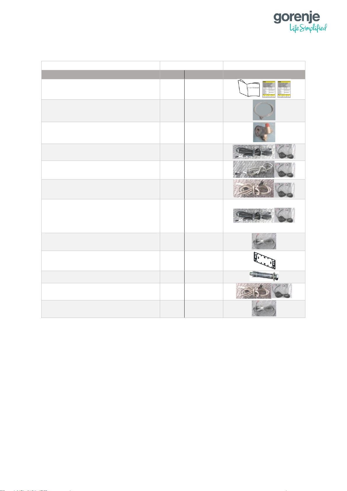
1.4 INCLUDED IN THE PACKAGE
NAME
QUANTITY
SYMBOLIC IMAGE
SPLIT
COMPACT
Installation Manual, Warranty cards
1
1
Drain pipe
1
1
Safety kit
1
1
TR – Room temp. sensor +
extension cable (10m)
1
1
TC – Heat/Cool temp. sensor +
extension cable (10m)
1
1
TW – DHW temp sensor + extension
cable (10m)
1
1
TV1 – mixing circuit 1 temp. sensor
+ extension cable (10m)
TV2 – mixing circuit 1 temp. sensor
+ extension cable (10m)
1
1
Communicaton cable
(20m)(shielded)
1
1
Bracket for indoor unit
1
1
Expansion bolts
2
1
Connection cable for Tui, Tuo, Tup
(20m)(shielded)
/
3 x 1
Connection cable for the Flow
Switch (20m) (shielded)
/
1

5
1.5 TECHNICAL TABLE
1.5.1 AEROGOR ECO COMPACT INVERTER 10A, 13A
MODEL
ECO COMPACT INVERTER 10A
ECO COMPACT INVERTER 13A
ErP Energy efficiency class
A++
A++
SCOP 35°C (floor heating) EN 14825
3,83
4,08
P
design
for SCOP EN 14825
6,3 kW
7,46 kW
HEATING MODE (A7/W35)
Heating capacity*
4,57 – 10,50 kW
4,1 -12,2 kW
COP - Coefficient of Performance*
3,80 – 4,71
4,0 - 4,57
Max. temperature of heating water
55 °C
55 °C
Operating range of heat pump - Heating (Ambient temp.)
-25 do +45 °C
-25 do +45 °C
COOLING MODE (A35/W7)
Cooling capacity**
2,60 – 8,00 kW
2,34 – 7,91 kW
Rated input power**
1,10 – 3,50
0,97 – 2,98 kW
EER - Energy Efficiency Ratio**
2,30 – 3,22 kW
2,40 – 3,03
Min. temperature of cooling water
7 °C
7 °C
Operating range of heat pump - Cooling (Ambient temp.)
0 to +65 °C
0 to +65 °C
POWER SUPPLY - SPECIFICATION
Voltage
220-240 V/50 Hz/1 Ph
220-240 V/50 Hz/1 Ph
Rated input power*
0,91 – 3,05 kW
0,96 - 3,02 kW
Fuse for heat pump
1 X 1p/20A/C
1 x 1p/20A/C
Fuse for electrical flow heater
3 X 1p/10A/C
3 x 1p/10A/C
REFRIGERANT SPECIFICATION
Type of refrigerant
R410A
R410A
Refrigerant - mass
1,9 kg
3 kg
GWP (global warming potential)
2088 GWP
2088 GWP
Quantity of hydrofluorocarbons in tonnes of CO2 equivalent
4,051 t CO2 Equiv.
6,264 t CO2 Equiv.
Type of compressor
DC inverter (twin rotary)
DC inverter (twin rotary)
Hermetically sealed equipment (indoor/outdoor unit)
Yes
Yes
Type fo connection between outdoor-indoor unit
Refrigerant connection
Water connection
Dimensions of refrigerant pipes connectors
3/8” - 1/2”
/
FAN
Fan type
1 x Axial
2 x Axial
Air flow
3100 m3/h
4100 m3/h
Rated power
60 W
2 x 60 W
„ESP“ – External Static Pressure of the Fan (data per piece)
45 W
50 W
WATER SIDE HEAT EXCHANGER
Type
Plate heat exchanger
Plate heat exchanger
Pressure drop
30 kPa
40 kPa
Dimensions of water piping connection
G1"
G1"
ALLOWABLE FLOW - SECONDARY (WATER) SIDE
Min. water flow
1,15 m3/h
1,32 m3/h
Nominal water flow
1,44 m3/h
2,2 m3/h
Max. water flow
2,16 m3/h
2,63 m3/h
SOUND POWER AND PRESSURE LEVEL
Sound power level LwA - Indoor unit
45 dB(A)
46 dB(A)
Sound power level LwA - Outdoor unit
58 dB(A)
59 dB(A)
SOUND PRESSURE LEVEL ON DISTANCE
Indoor unit - 1 m
37 dB(A)
38 dB(A)
Outdoor unit - 1 m
50 dB(A)
51 dB(A)
Outdoor unit - 5 m
36 dB(A)
37 dB(A)
Outdoor unit - 10 m
30 dB(A)
31 dB(A)
Outdoor unit - 15 m
26 dB(A)
27 dB(A)
NET DIMENSIONS
Indoor unit (WxHxD)
505 x 946 x 288 mm
562 x 686 x 260 mm
Outdoor unit (WxHxD)
1044 × 763 × 414 mm
1258 x 1195 x 407 mm
NET WEIGHT
Indoor unit
50 kg
25 kg
Oudoor unit
75 kg
140 kg
SERIAL INTEGRATED COMPONENTS
Electrical flow heater
6 kW (3ph / 2 stages)
6 kW (3ph / 2 stages)
Circulation water pump - A energy class
Grundfos UPM GEO 25-85 180
Grundfos UPM GEO 25-85 180
3-way diverting valve for DHW tank
Optional external
Optional external
6
1.5.2 AEROGOR ECO INVERTER 10A, 13A
MODEL
ECO INVERTER 10A
ECO INVERTER 13A
ErP Energy efficiency class
A++
A++
SCOP 35°C (floor heating) EN 14825
3,83
4,08
P
design
for SCOP EN 14825
6,3 kW
7,46 kW
HEATING MODE (A7/W35)
Heating capacity*
4,57 – 10,50 kW
4,1 -12,2 kW
COP - Coefficient of Performance*
3,80 – 4,71
4,0 - 4,57
Max. temperature of heating water
55 °C
55 °C
Operating range of heat pump - Heating (Ambient temp.)
-25 do +45 °C
-25 do +45 °C
COOLING MODE (A35/W7)
Cooling capacity**
2,60 – 8,00 kW
2,34 – 7,91 kW
Rated input power**
1,10 – 3,50 kW
0,97 – 2,98 kW
EER - Energy Efficiency Ratio**
2,30 – 3,22
2,40 – 3,03
Min. temperature of cooling water
7 °C
7 °C
Operating range of heat pump - Cooling (Ambient temp.)
0 to +65 °C
0 to +65 °C
POWER SUPPLY - SPECIFICATION
Voltage
220-240 V/50 Hz/1 Ph
220-240 V/50 Hz/1 Ph
Rated input power*
0,91 – 3,05 kW
0,96 - 3,02 kW
Fuse for heat pump
1 X 1p/20A/C
1 X 1p/20A/C
Fuse for electrical flow heater
3 X 1p/10A/C
3 X 1p/10A/C
REFRIGERANT SPECIFICATION
Type of refrigerant
R410A
R410A
Refrigerant - mass
1,9 kg
3 kg
GWP (global warming potential)
2088 GWP
2088 GWP
Quantity of hydrofluorocarbons in tonnes of CO2 equivalent
4,051 t CO2 Equiv.
6,264 t CO2 Equiv.
Type of compressor
DC inverter (twin rotary)
DC inverter (twin rotary)
Hermetically sealed equipment (indoor/outdoor unit)
Yes
Yes
Type fo connection between outdoor-indoor unit
Refrigerant connection
Refrigerant connection
Dimensions of refrigerant pipes connectors
3/8” - 1/2”
3/8” - 5/8”
FAN
Fan type
1 x Axial
2 x Axial
Air flow
3100 m3/h
4100 m3/h
Rated power
60 W
2 x 60 W
„ESP“ – External Static Pressure of the Fan (data per piece)
45 W
50 W
WATER SIDE HEAT EXCHANGER
Type
Plate heat exchanger
Plate heat exchanger
Pressure drop
30 kPa
40 kPa
Dimensions of water piping connection
G1"
G1"
ALLOWABLE FLOW - SECONDARY (WATER) SIDE
Min. water flow
1,15 m3/h
1,32 m3/h
Nominal water flow
1,44 m3/h
2,2 m3/h
Max. water flow
2,16 m3/h
2,63 m3/h
SOUND POWER AND PRESSURE LEVEL
Sound power level LwA - Indoor unit
45 dB(A)
46 dB(A)
Sound power level LwA - Outdoor unit
58 dB(A)
59 dB(A)
SOUND PRESSURE LEVEL ON DISTANCE
Indoor unit - 1 m
37 dB(A)
38 dB(A)
Outdoor unit - 1 m
50 dB(A)
51 dB(A)
Outdoor unit - 5 m
36 dB(A)
37 dB(A)
Outdoor unit - 10 m
30 dB(A)
31 dB(A)
Outdoor unit - 15 m
26 dB(A)
27 dB(A)
NET DIMENSIONS
Indoor unit (WxHxD)
505 x 946 x 288 mm
505 x 946 x 288 mm
Outdoor unit (WxHxD)
1044 × 763 × 414 mm
1123 x 1195 x 400 mm
NET WEIGHT
Indoor unit
50 kg
58 kg
Oudoor unit
75 kg
113 kg
SERIAL INTEGRATED COMPONENTS
Electrical flow heater
6 kW (3ph / 2 stages)
6 kW (3ph / 2 stages)
Circulation water pump - A energy class
Grundfos UPM GEO 25-85 180
Grundfos UPM GEO 25-85 180
3-way diverting valve for DHW tank
Optional external
Optional external
7
1.5.3 AEROGOR POWER EVI INVERTER 15A, 18A
MODEL
POWER EVI INVERTER 15A
POWER EVI INVERTER 18A
ErP Energy efficiency class
A+
A+
SCOP 35°C (floor heating) EN 14825
3,46
3,42
P
design
for SCOP EN 14825
10,97 kW
13,48 kW
HEATING MODE (A7/W35)
Heating capacity*
6,60 - 14,60 kW
8,2 - 18,0 kW
COP - Coefficient of Performance*
3,80 - 4,46
3,91 - 4,43
Max. temperature of heating water
55 °C
55 °C
Operating range of heat pump - Heating (Ambient temp.)
-25 do +45 °C
-25 do +45 °C
COOLING MODE (A35/W7)
Cooling capacity**
5,56 - 10,00 kW
6,4 - 15,1 kW
Rated input power**
1,57 - 3,82 kW
2,19 – 6,42 kW
EER - Energy Efficiency Ratio**
1,85 - 3,52
2,35 - 2,92
Min. temperature of cooling water
7 °C
7 °C
Operating range of heat pump - Cooling (Ambient temp.)
0 to +65 °C
0 to +65 °C
POWER SUPPLY - SPECIFICATION
Voltage
380-415 V/50 Hz/3 Ph
380-415 V/50 Hz/3 Ph
Rated input power*
1,53 - 4,92 kW
1,53 - 4,92 kW
Fuse for heat pump
1 x 3p/16A/C
1 x 3p/16A/C
Fuse for electrical flow heater
3 x 1p/10A/C
3 x 1p/10A/C
REFRIGERANT SPECIFICATION
Type of refrigerant
R410A
R410A
Refrigerant - mass
6,2 kg
6,6 kg
GWP (global warming potential)
2088 GWP
2088 GWP
Quantity of hydrofluorocarbons in tones of CO2 equivalent
12,946 t CO2 Equiv.
13,780 t CO2 Equiv.
Type of compressor
Scroll EVI DC Inverter
Scroll EVI DC Inverter
Hermetically sealed equipment (indoor/outdoor unit)
Yes
Yes
Type fo connection between outdoor-indoor unit
Refrigerant connection
Refrigerant connection
Dimensions of refrigerant pipes connectors
3/8" - 3/4"
3/8" - 3/4"
FAN
Fan type
2 x Axial
2 x Axial
Air flow
4200 m3/h
4500 m3/h
Rated power
2 x 80
2 x 80
„ESP“ – External Static Pressure of the Fan (data per piece)
50
50
WATER SIDE HEAT EXCHANGER
Type
Plate heat exchanger
Plate heat exchanger
Pressure drop
35
35
Dimensions of water piping connection
G1"
G1"
ALLOWABLE FLOW - SECONDARY (WATER) SIDE
Min. water flow
1,4 m3/h
1,86 m3/h
Nominal water flow
2,56 m3/h
3,09 m3/h
Max. water flow
2,7 m3/h
3,7 m3/h
SOUND POWER AND PRESSURE LEVEL
Sound power level LwA - Indoor unit
47 dB(A)
52 dB(A)
Sound power level LwA - Outdoor unit
68 dB(A)
72 dB(A)
SOUND PRESSURE LEVEL ON DISTANCE
Indoor unit - 1 m
39 dB(A)
44 dB(A)
Outdoor unit - 1 m
60 dB(A)
65 dB(A)
Outdoor unit - 5 m
46 dB(A)
51 dB(A)
Outdoor unit - 10 m
40 dB(A)
45 dB(A)
Outdoor unit - 15 m
36 dB(A)
41 dB(A)
NET DIMENSIONS
Indoor unit (WxHxD)
505 x 946 x 303 mm
505 x 946 x 288 mm
Outdoor unit (WxHxD)
1172 x 1194 x 410 mm
1440 x 1271 x 460 mm
NET WEIGHT
Indoor unit
32 kg
55 kg
Oudoor unit
151 kg
180 kg
SERIAL INTEGRATED COMPONENTS
Electrical flow heater
6 kW (3ph / 2 stages)
6 kW (3ph / 2 stages)
Circulation water pump - A energy class
Grundfos UPM GEO 25-85 180
Grundfos UPMXL GEO25-125 130
3-way diverting valve for DHW tank
Optional external
Optional external
(*) Measured according to standard EN 14511. Heating condition: water inlet/outlet temperature 30°C/35°C, ambient
temperature DB/WB 7°C/6°C.
(**) Measured according to standard EN 14511. Cooling condition: water inlet/outlet temperature 12°C/7°C and ambient
temperature 35°C.
8
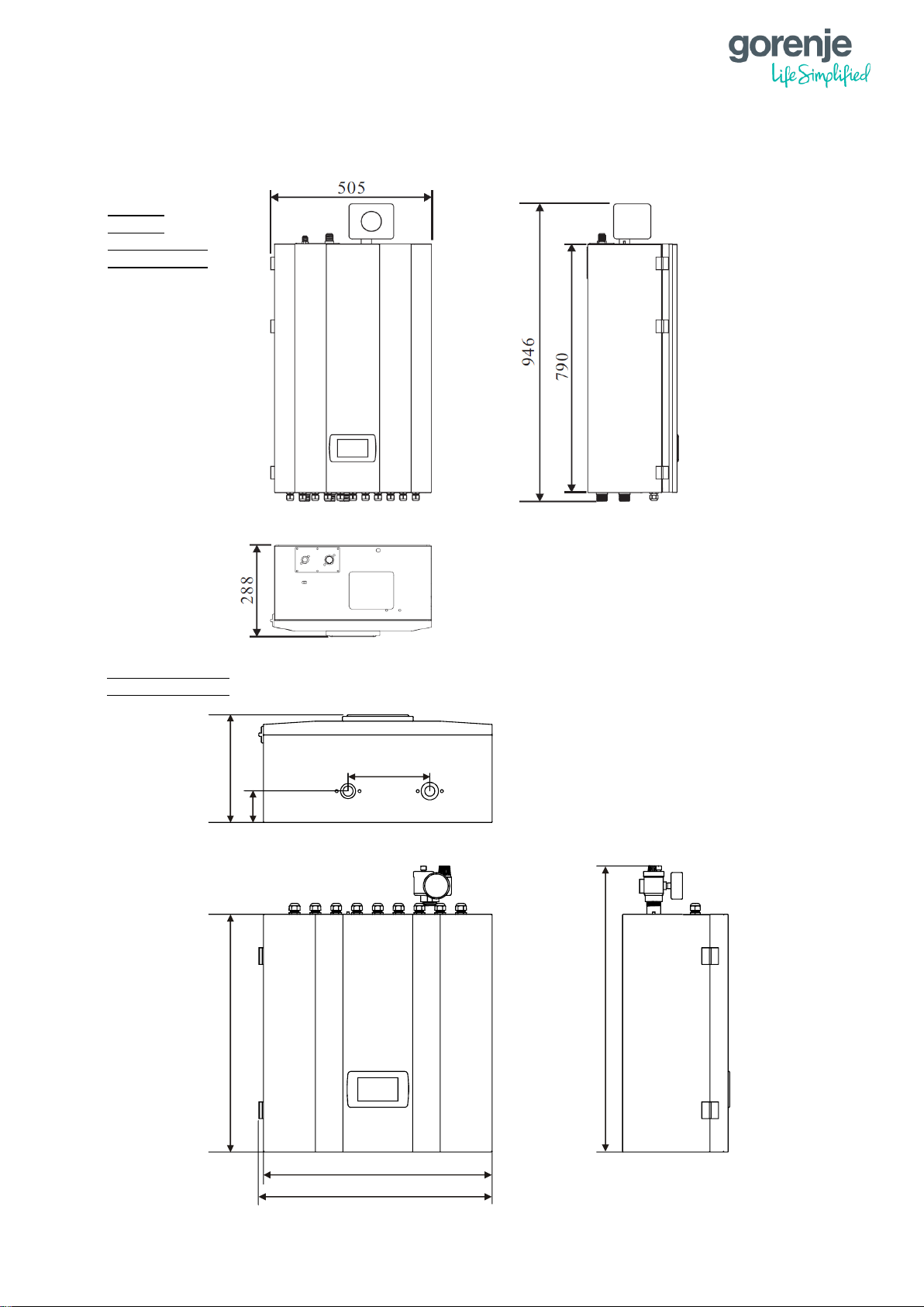
1.6 DIMENSIONS
1.6.1 INDOOR UNITS
ECO 10 A
ECO 13 A
POWER EVI 15 A
POWER EVI 18 A
ECO COMPACT 10 A
ECO COMPACT 13 A
Unit:mm
260
196.5
570
550
686
561.5
75
9
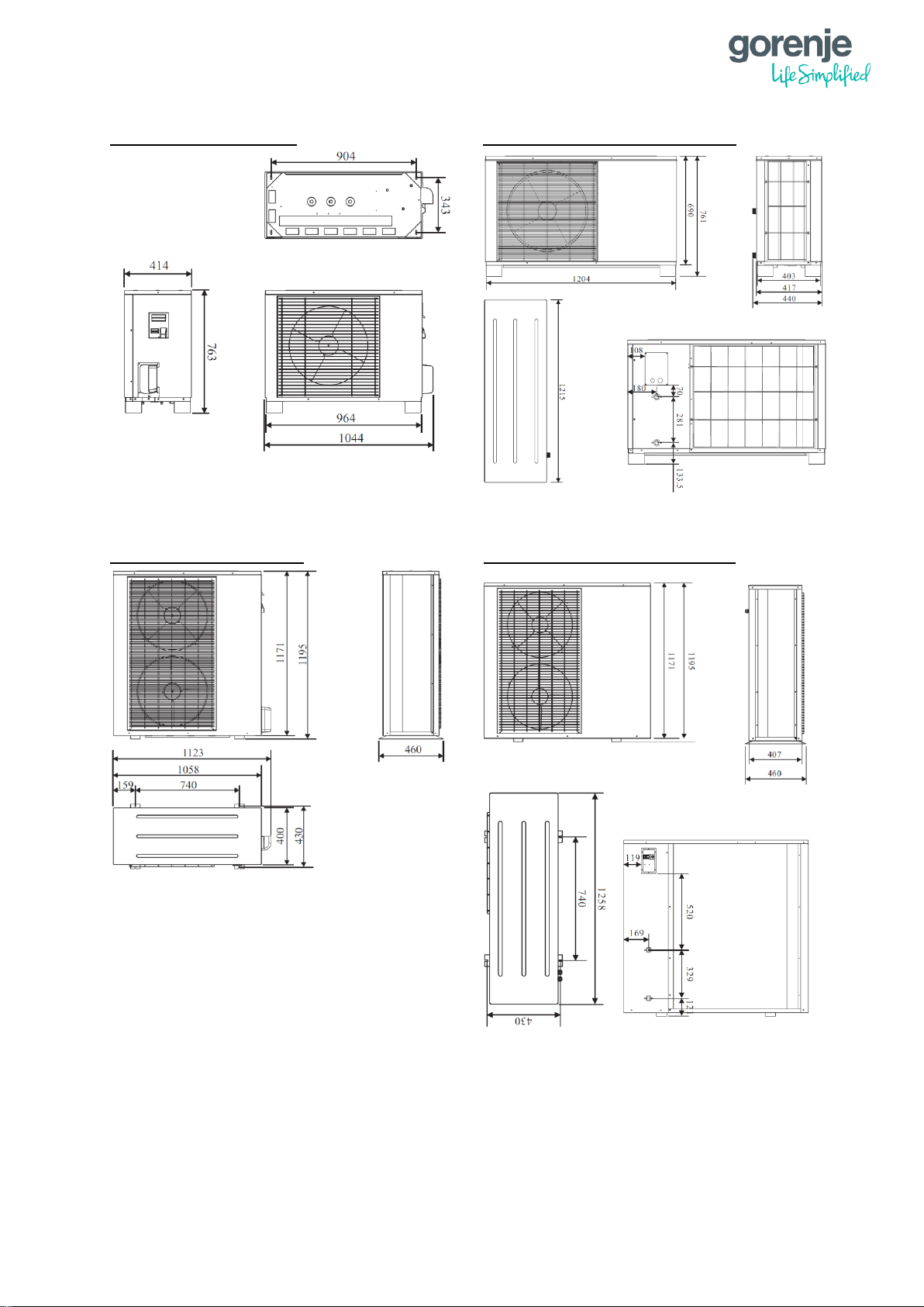
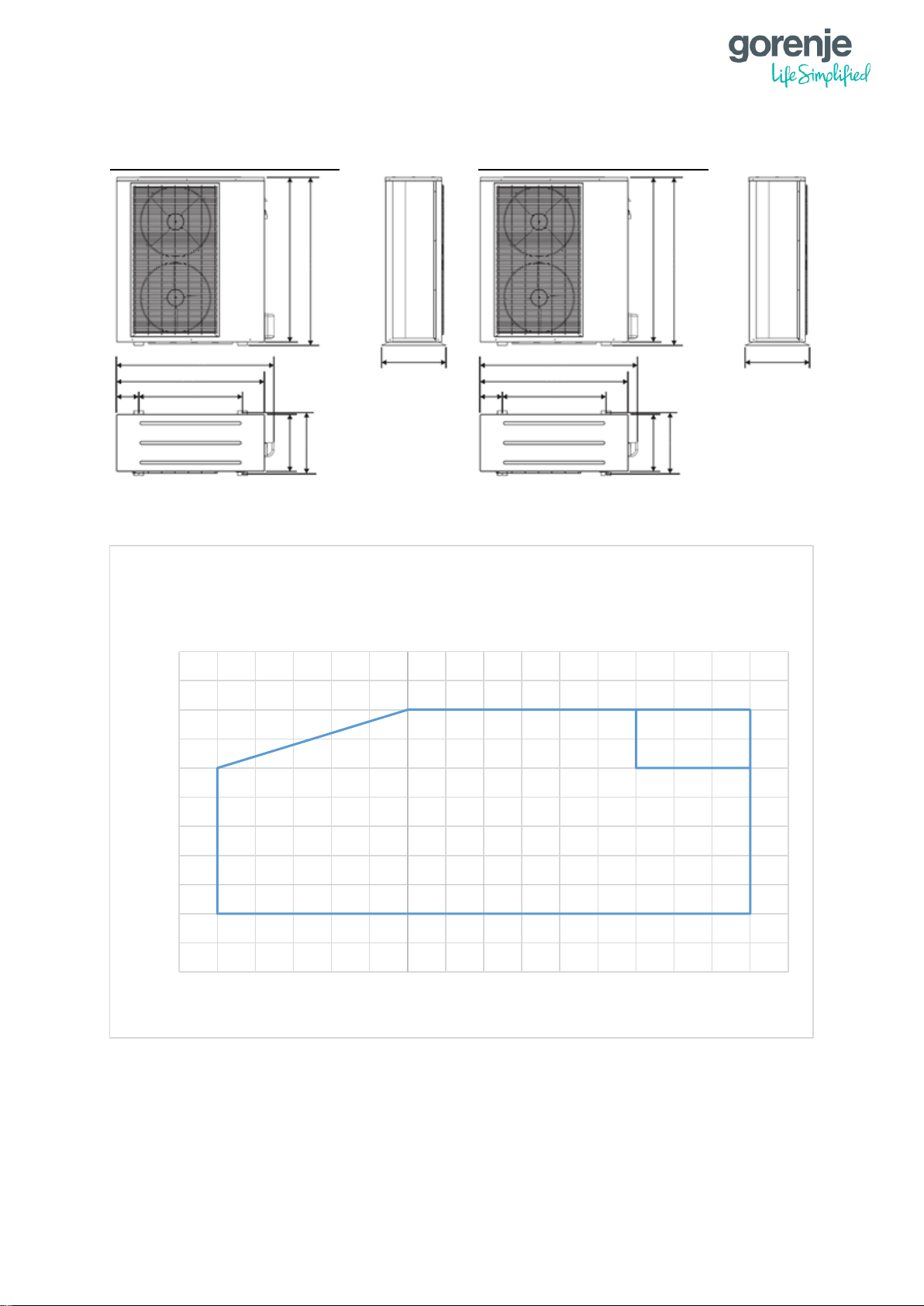
1.6.2 OUTDOOR UNITS
AEROGOR ECO INVERTER 10A AEROGOR ECO COMPACT INVERTER 10A
AEROGOR ECO INVERTER 13A, AEROGOR ECO COMPACT INVERTER 13A
10
AEROGOR POWER EVI INVERTER 15A AEROGOR POWER EVI INVERTER 18A
1.7 OPERATING RANGE
10
15
20
25
30
35
40
45
50
55
60
65
-30 -25 -20 -15 -10 -5 0 5 10 15 20 25 30 35 40 45 50
Outlet water temperature [
°C]
Outside Ambient temperature [°C]
Operating range - heating mode:
Aerogor ECO Inverter 10-13 A
Aerogor COMPACT ECO Inverter 10-13 A
ECO
1443
1373
860
222
460
402
460
1272
1294
460
1241
1171
715
182
1171
1193
402
460
11
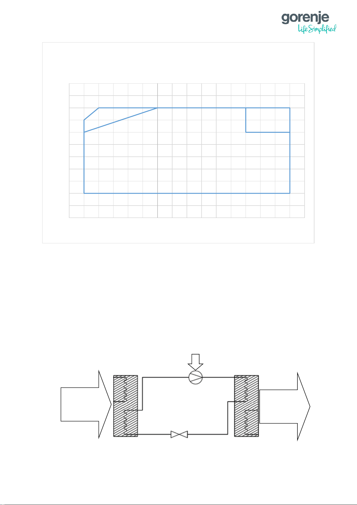
1.8 WORKING PRINCIPLE
A heat pump operates similarly as a refrigerator. In a refrigerator, liquids evaporate due to
received thermal energy from the surrounding air and this energy is emitted at a desired spot
during condensation (Carnot’s cycle). A heat pump works in the opposite direction: it accepts
thermal energy from the surrounding air and emits it in heated premises, using the natural
heat collector of the environment. Ground and surface water, earth’s warmth, solar energy
and ambient air can be used as energy sources. The system is composed of four units:
evaporator, compressor, condenser and damper. Heat energy is transferred via the coolant.
In the evaporator, the coolant receives heat energy and evaporates. In the compressor, the
vapour is compressed, which makes it heat up intensively. This hot vapour transmits thermal
energy from the condenser to the heating water and liquefies. In the damper, the coolant
expands (pressure reduces to the starting pressure, from there it proceeds to the evaporator
and the cycle repeats).
10
15
20
25
30
35
40
45
50
55
60
65
-30 -25 -20 -15 -10 -5 0 5 10 15 20 25 30 35 40 45 50
Maximum outlet water temperture [
°C]
Outside ambient temperature [°C]
Operating range - heating mode:
Aerogor POWER EVI Inverter 15 A
Aerogor POWER EVI Inverter 18 A
Heat from
ambient
Produced
heat for
heating
Electric
energy
ECO
EVI
Compressor
Expansion
valve
Evaporator
Evaporator
Condenser
Condenser
12
Inverter heat pumps use variable-speed compressors. Traditional heat pumps use fixed
power/rotation speed compressors. In inverter compressors, the compressor speed
constantly adapts to the heat losses of the room and the energy value of the source (air,
brine or water, depending on the system). In traditional heat pumps, the power of the
compressor is always the same. Compressor starts with full power and when it achieves the
desired values/temperatures, it shuts off and waits until it restarts. Inverter heat pumps work
for a longer period, but with lower power (adjusting to the premises), which means lower
consumption of electric energy.
1.9 MAIN COMPONENTS
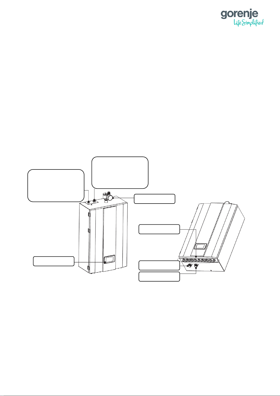
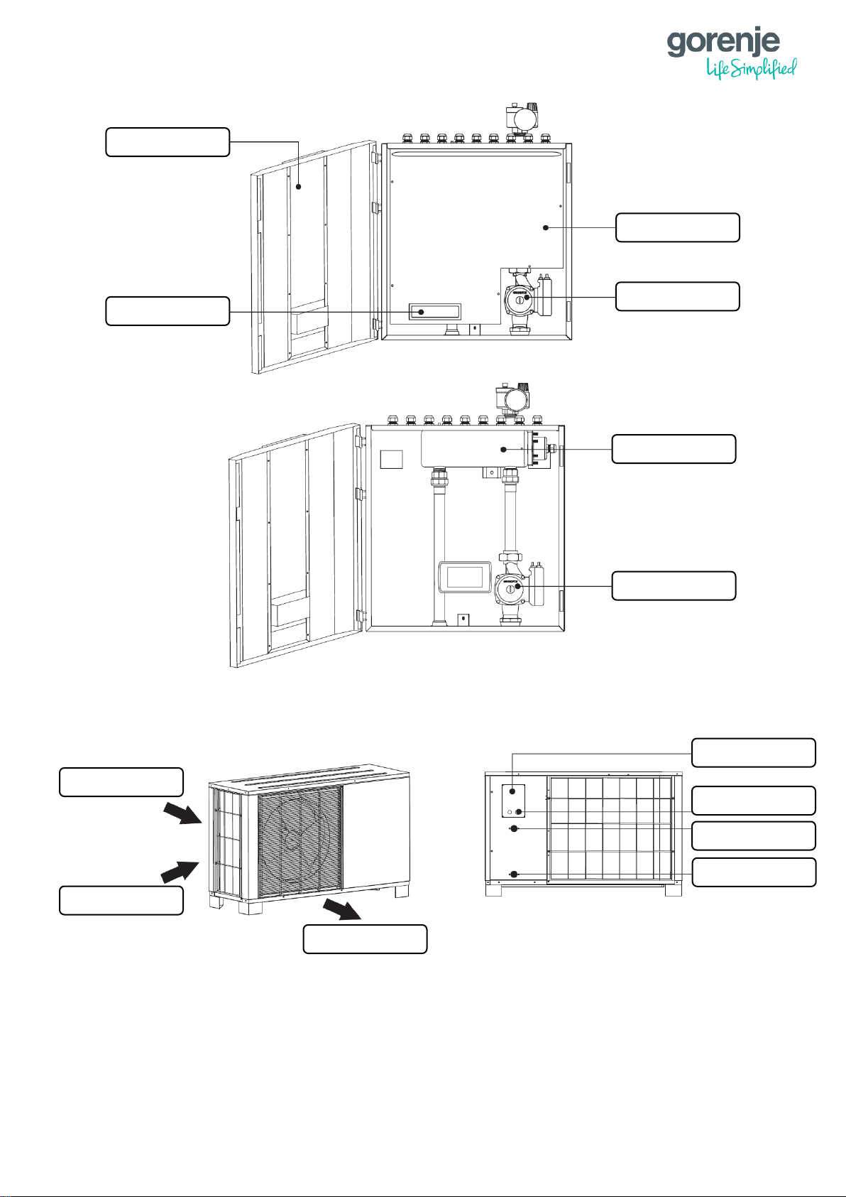
1.9.1 INDOOR UNITS
1.9.1.1 AEROGOR ECO INVERTER 10A/13A AND AEROGOR POWER EVI INVERTER
15A/18A
Refrigerant Connector
ECO 10A: 3/8"
ECO 13A: 3/8"
POWER EVI 15A: 3/8"
POWER EVI 18A: 3/8"
Refrigerant Connector
ECO 10A: 1/2"
ECO 13A: 5/8"
POWER EVI 15A: 3/4"
POWER EVI 18A: 3/4"
Operation panel
Cable gland
Water outlet G1"
Water inlet G1"
Safety valve kit
13
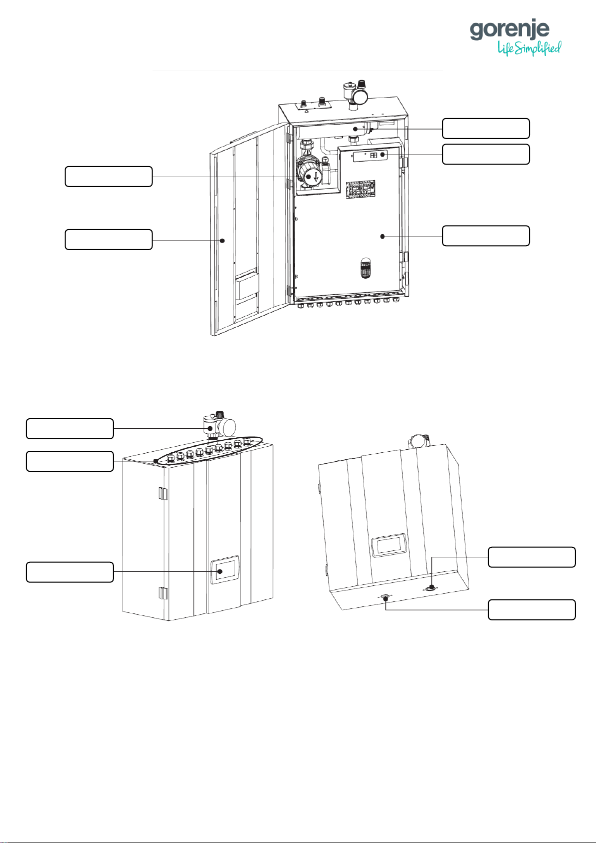
1.9.1.2 AEROGOR ECO COMPACT INVERTER 10A/13A
Operation panel
Cable gland
Safety valve kit
Water inlet G1"
Water outlet G1"
Water pump
Door
Electric heater
Digital thermostat
Electric box cover
14
1.9.2 OUTDOOR UNITS
1.9.2.1 AEROGOR ECO COMPACT INVERTER 10A
Electric heater
Water pump
Water pump
Electric box cover
Digital thermostat
Door
Cover
Cable fixture
Air inlet
Air inlet
Air outlet
Water outlet G1"
Water inlet G1"
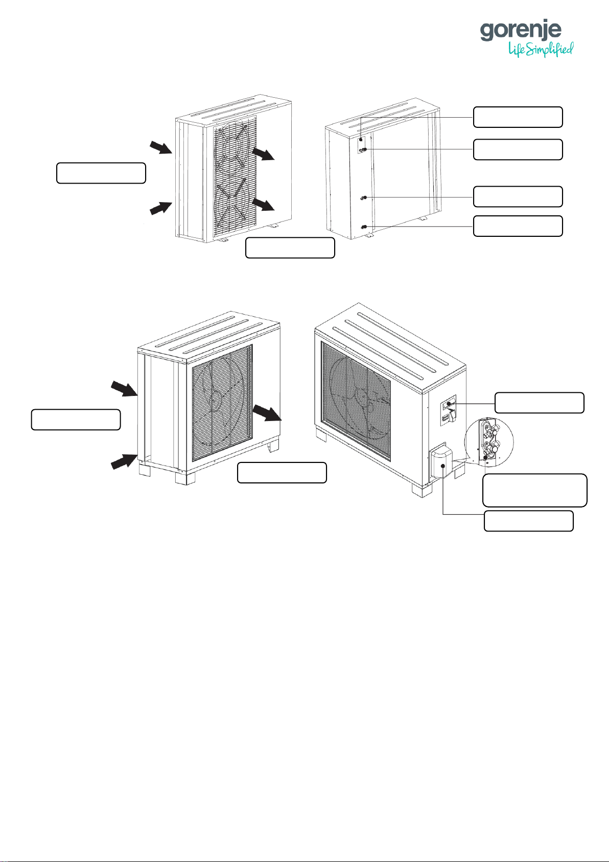
15
1.9.2.2 AEROGOR ECO COMPACT INVERTER 13A
1.9.2.3 AEROGOR ECO INVERTER 10A
Air inlet
Air outlet
Cover
Cable fixture
Water outlet G1"
Water inlet G1"
Air inlet
Air outlet
Handle
Refrigerant connector
3/8" and 1/2"
Valve cover
16
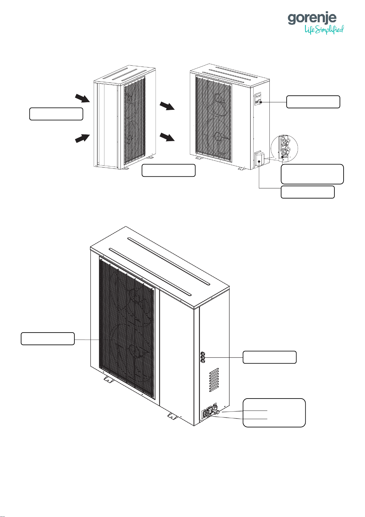
1.9.2.4 AEROGOR ECO INVERTER 13A
1.9.3 AEROGOR POWER EVI INVERTER 15A/ 18A
Handle
Refrigerant connector
3/8" and 5/8"
Valve cover
Air inlet
Air outlet
Refrigerant connector
3/4"
3/8"
Cable gland
Air outlet grill
17
2 INSTALLATION
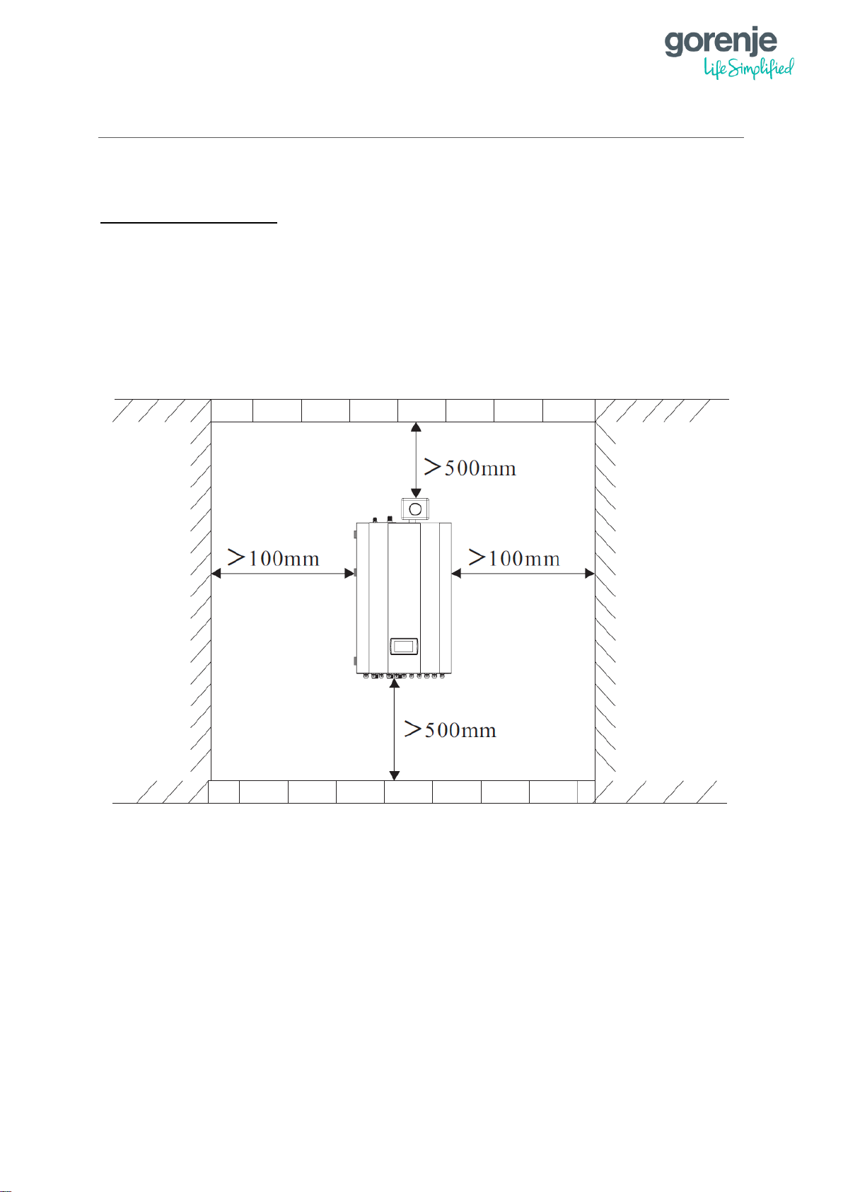
2.1 INSTALLATION OF THE INDOOR UNIT
INSTALLATION NOTES:
1. The indoor unit should be installed indoors and mounted on the wall with water
connections facing downwards.
2. The indoor unit shall be placed in a dry and well-ventilated environment.
3. It is forbidden to install the indoor unit in an environment where there exist volatile,
corrosive or flammable liquids or gases.
4. There should be enough space left around the indoor unit for further maintenance.
Please choose a suitable position to install the indoor unit as follows:
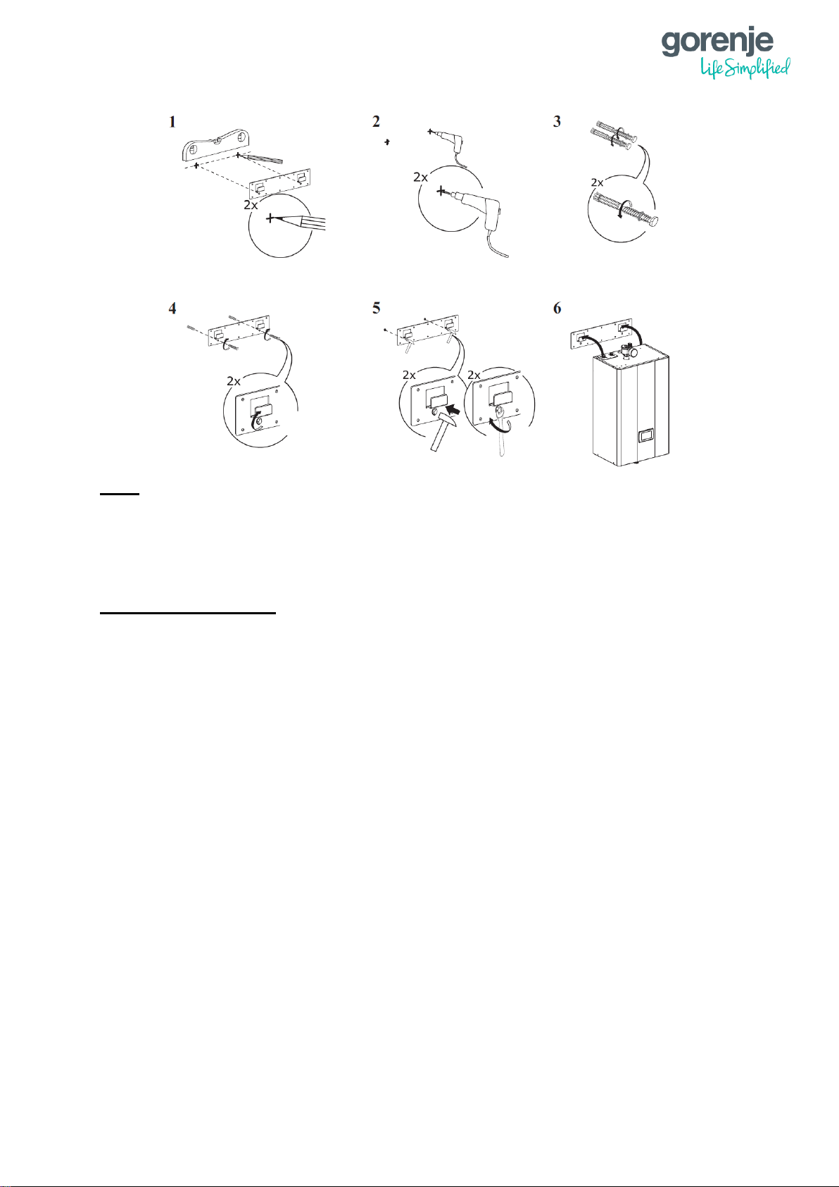
Indoor unit should be mounted on the wall as followed:
1. Take out the expansion bolts and mounting board from the box and put the mounting
board on the wall horizontally.
2. Mark the location of the holes for the bolts on the wall.
3. Drill the holes with proper diameter for the expansion bolts.
4. Unscrew the nuts from the expansion bolts.
5. Fix the mounting board on the expansion bolts a little bit, but don’t be too tight.
6. Use a hammer to pound the expansion bolts into the drilled holes.
7. Fasten the nuts by turning the wrench to fix the mounting board on the wall.
8. Hang the indoor unit onto the mounting board and make sure it’s placed well before
you let go your hands.
9. At this point, the installation is finished.
18
Note:
You must choose very firm wall for installation, otherwise the bolts may get loose and
therefore damaging the unit.
2.2 INSTALLATION OF THE OUTDOOR UNIT
INSTALLATION NOTES:
1. The outdoor unit can be located in an open space, corridor, balcony, roof or hanged
on the wall.
2. The outdoor unit shall be placed in dry and well-ventilated environment; If the outdoor
unit is installed in a humid environment, electronic components may get corroded or
short circuited.
3. Outdoor unit mustn’t be installed in an environment where there exist volatile,
corrosive or flammable liquids or gasses.
4. Please don’t install outdoor unit close to bedroom or living room because it produces
some noise when it’s operating.
5. It is recommended to install an awning above the outdoor unit, to protect the snow
from clogging in the air inlet and outlet to ensure normal operation.
6. Please ensure there is drainage system around the location to drain the condensate
water under defrost mode.
7. When installing the unit, tilt it by 1 cm/m to enable rain water drainage.
8. Install outdoor unit far away from the exhaust port of the kitchen to avoid oil smoke
entering into outdoor unit heat exchanger.
9. Please don’t install the indoor and outdoor unit in damp locations. The units should be
free from corrosive and moisture surrounding otherwise the lifetime of the unit might
be shortened.
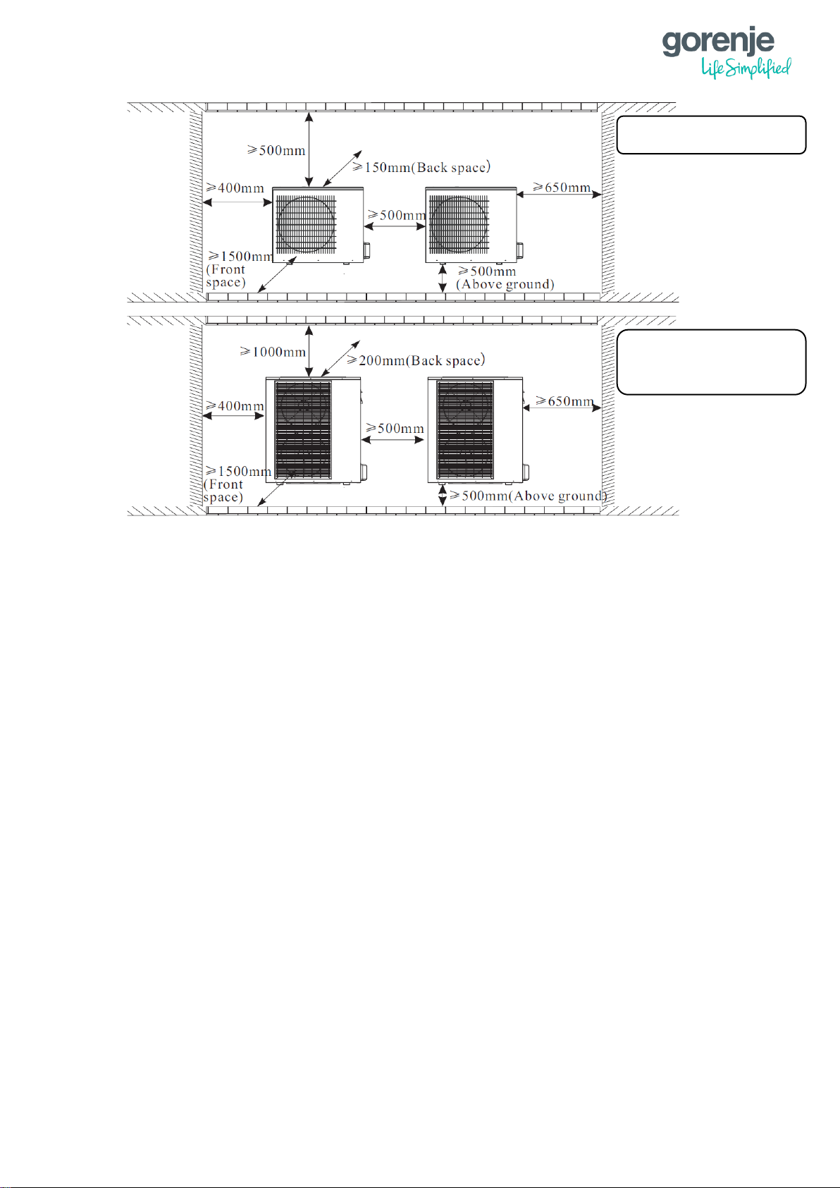
10. Please ensure enough space around the outdoor unit for better ventilation and
maintenance.
Please refer to the illustration below.
19
User can either use the dedicated mounting bracket from the supplier or prepare a suitable
bracket for the unit installation. Make sure the installation meets the following requirements:
1. The unit must be installed on flat concrete blocks or a dedicated mounting bracket.
The bracket should be able to support at least 5 times of the unit weight.
2. All nuts must be tightened after the bracket is fixed otherwise it may cause damage to
the equipment.
3. Double check and make sure the installation of the unit is firm enough.
4. The bracket can be made from stainless steel, galvanized steel, aluminium and other
materials as required by the user.
5. Besides the mounting bracket, the user can also install the outdoor unit on two
concrete blocks or a raised concrete platform. Please make sure that the unit is
securely fastened after installation.
6. Please see the dimensions of outdoor unit when choosing a suitable wall bracket.
Hole for piping should lean a little bit to outside (≥ 8 degrees) to keep the rain or condensate
water from flowing back indoors.
AEROGOR ECO INVERTER 10A
AEROGOR COMPACT INVERTER 10A
AEROGOR ECO INVERTER 13A
AEROGOR COMPACT INVERTER 13A
AEROGOR POWER EVI INVERTER 15A
AEROGOR POWER EVI INVERTER 18A
20
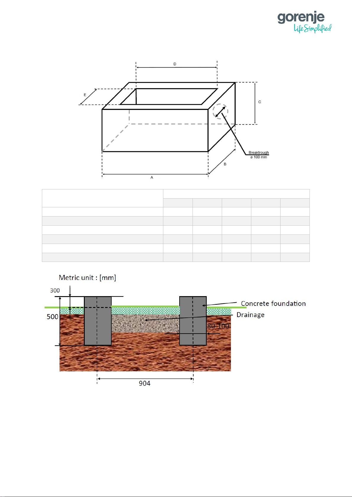
2.3 FOUNDATION
MODEL
SIZE (mm)
A B C D E
ECO COMPACT INVERTER 10A
1390
740
500
1230
580
ECO COMPACT INVERTER 13A
1460
720
500
1300
560
ECO INVERTER 10A
1230
600
500
1070
440
ECO INVERTER 13A
1320
600
500
1160
440
POWER EVI INVERTER 15A
1430
600
500
1270
440
POWER EVI INVERTER 18A
1700
600
500
1540
440
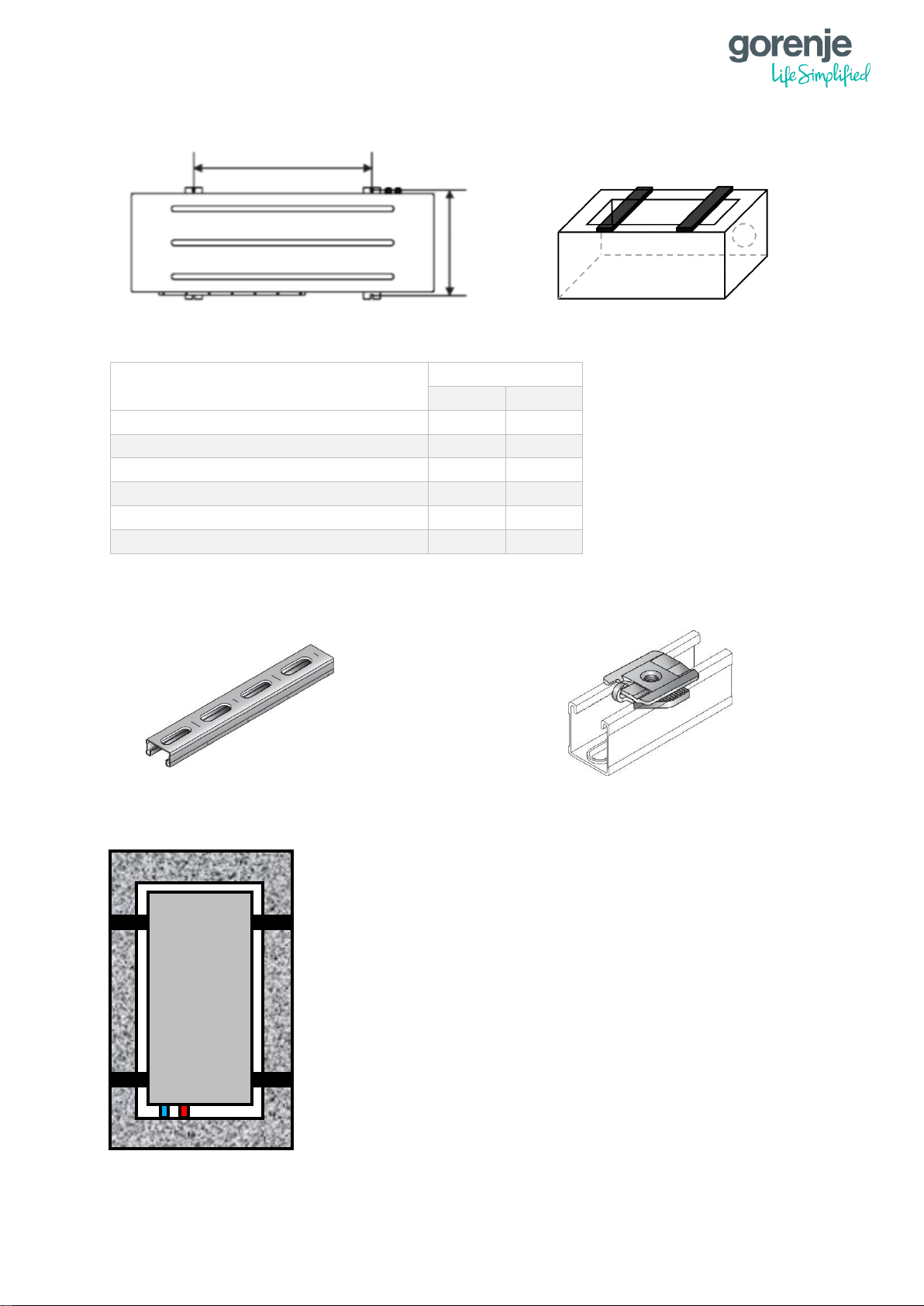
21
MODEL
SIZE (mm)
X
Y
ECO COMPACT INVERTER 10A
1140
340
ECO COMPACT INVERTER 13A
740
430
ECO INVERTER 10A
904
343
ECO INVERTER 13A
740
430
POWER EVI INVERTER 15A
720
430
POWER EVI INVERTER 18A
720
430
2.3.1 INSTALLATION OF C PROFILE AND LEGS
X
MM-C-16 Double installation profile
MM-S Connector for hose clamp
Y
H
Plan view of the heat pump
fixed on the foundation
22
2.4 INSTALATION OF THE REFRIGERANT SYSTEM (SPLIT TYPE)
NOTE:
Only certified personnel are allowed to connect and operate with the refrigerant
system.
It is forbidden to start the unit without Evacuating the refrigerant system.
Pipes used for installation must comply with the specifications of the heat pump
Before starting the unit, always check if the refrigerant connections are sealed and
there is no leakage in the system.
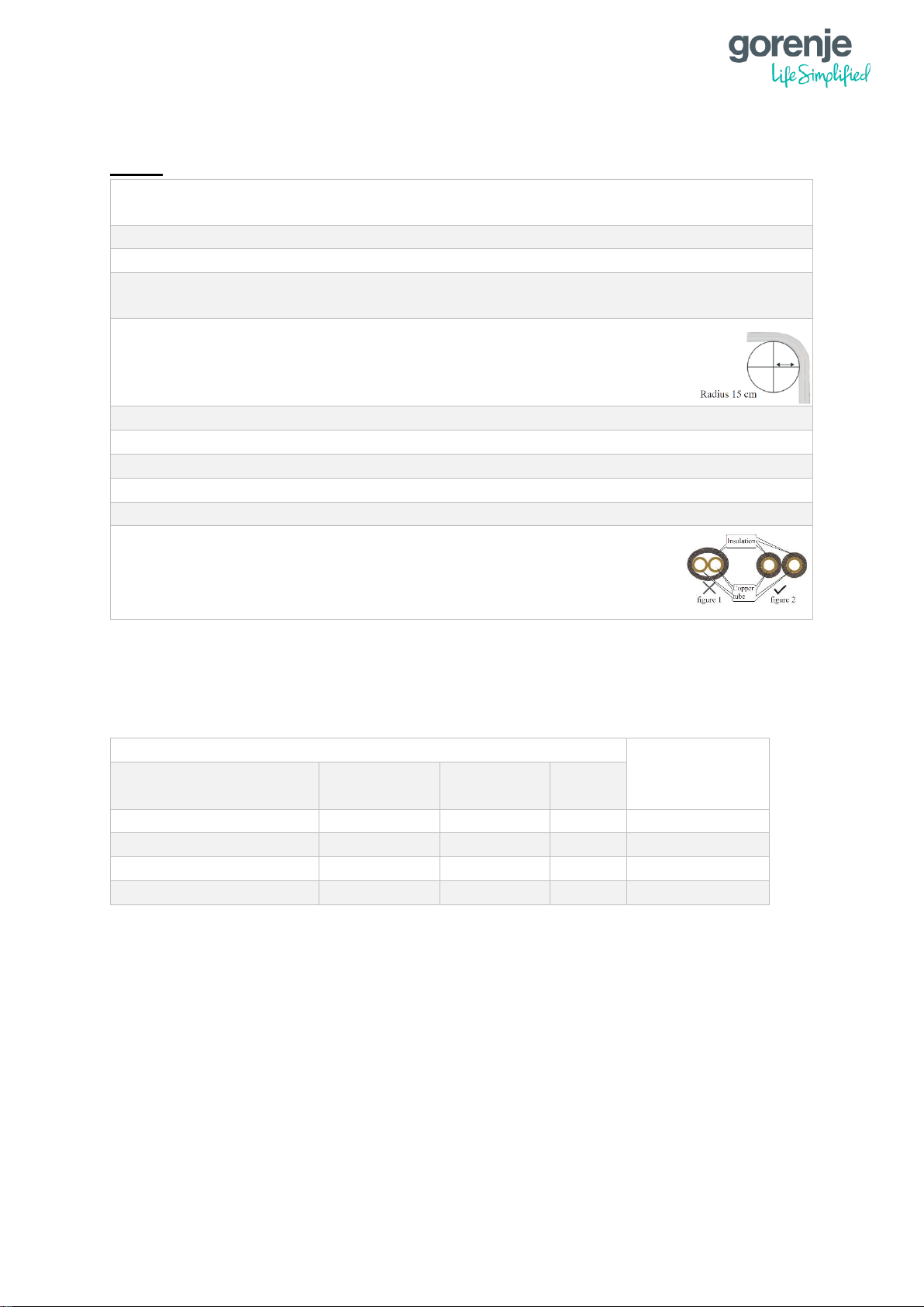
The radius at pipe bends must not be less than 15 cm and the pipes
have to be without flaws.
Do not let any dirt in the refrigerant system
Always use tools without flaws.
Always Evacuate the refrigerant to 500 microns or below.
Evacuating the refrigerant system at sub-zero temperatures is forbidden.
Evacuating the refrigerant system at sub-zero temperatures is forbidden.
When insulating refrigerant pipes, insulate each pipe separately.
The split type heat pumps are factory loaded for a specific length. If the length is longer
than factory load, please check that it does not exceed the maximum length shown in the
table below:
For each meter that is longer than the factory load, you must add 40 g of refrigerant.
REFRIGIRANT PIPING LENGTH
CONNECTIONS
HEAT
PUMP
FACTORY
LOAD
MAXIMUM
LENGTH
ADD
ECO Inverter 10A
5 meters
12 meters
40 g/m
1/4" and 1/2"
ECO Inverter 13A
10 meters
15 meters
40 g/m
3/8" and 1/2"
Power EVI Inverter 15A
15 meters
18 meters
40 g/m
3/8" and 5/8"
Power EVI Inverter 18A
15 meters
18 meters
40 g/m
3/8" and 3/4"
23
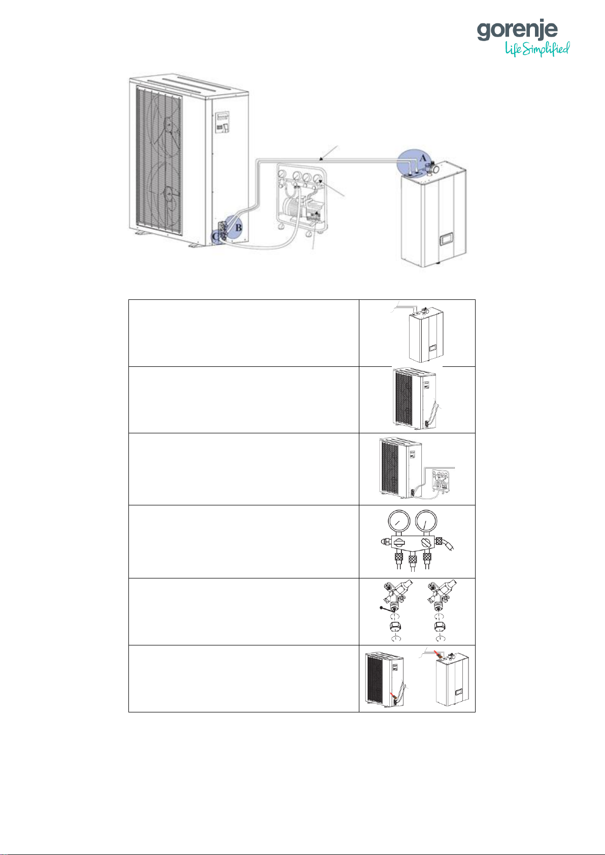
A – Connect the refrigerant piping to the
indoor unit.
B - Connect the other end of the refrigerant
pipes to the outdoor unit.
C – Prepare a vacuum pump and a
pressure gauge. Connect one tube of the
pressure gauge to the vacuum pump and
the other one to the high-pressure
refrigerant connector on the outdoor unit.
Open the pressure gauge and start the
vacuum pump to vacuum the unit to 500
microns or below. After that close, the
pressure gauge and stop vacuuming.
Take off the copper nuts off the connectors
and open the valves with hexagon spanner
as much as possible.
Check if there is any leakage with leakage
detector or soap water. If not, remove the
tubes of the gauges and put back the
copper nuts into the valves.
Vacuum pump
Pressure
gauge
Refrigerant pipe
connection
 Loading...