


Goodman CKL, CLJ, CRT, CLT, TWC REPAIR PARTS
...Service
Instructions
CKL, CLJ, CRT, CLT, TWC, CLQ & HDC Split System Remote Coolers and CPLE, CPLJ, CPRT, CPLT & HDP
Split System Remote Heat Pumps with R-22 Refrigerant
Blowers, Coils, & Accessories
This manual is to be used by qualified, professionally trained HVAC technicians only. Goodman does not assume any responsibility for property damage or personal injury for improper service procedures or services performed by an unqualified person.
RS6200004
May 2006
INDEX
IMPORTANTINFORMATION .......................................... |
4 |
PRODUCTIDENTIFICATION .......................................... |
6 |
HEAT PUMPS AND COOLERS ................................. |
6 |
COILS ........................................................................ |
9 |
AIR HANDLERS ...................................................... |
10 |
ACCESSORIES ....................................................... |
13 |
PRODUCTSPECIFICATIONS ....................................... |
17 |
CKL ......................................................................... |
20 |
CKL090-120 ............................................................. |
27 |
CLJ .......................................................................... |
30 |
CLT .......................................................................... |
37 |
CRT ......................................................................... |
41 |
TWC ........................................................................ |
46 |
HDC ......................................................................... |
48 |
CPLE ....................................................................... |
49 |
CPLE090-120 .......................................................... |
55 |
CPLJ ........................................................................ |
58 |
CPRT ....................................................................... |
62 |
CPLT........................................................................ |
67 |
HDP ......................................................................... |
70 |
UC ........................................................................... |
71 |
H.............................................................................. |
74 |
HT ............................................................................ |
75 |
CAUF ....................................................................... |
77 |
CAPF ....................................................................... |
78 |
CHPF ....................................................................... |
79 |
A18-61 ..................................................................... |
83 |
AR ........................................................................... |
86 |
AR COMMERCIAL SERIES ..................................... |
88 |
AH ........................................................................... |
91 |
AC ........................................................................... |
93 |
ACHP ...................................................................... |
96 |
AWB ........................................................................ |
97 |
ARUF ..................................................................... |
100 |
ARPF ..................................................................... |
103 |
ARPT ..................................................................... |
105 |
AER ....................................................................... |
107 |
AEPT ..................................................................... |
111 |
WMC ..................................................................... |
117 |
WMH ..................................................................... |
119 |
LOCATIONANDCLEARANCES ................................... |
39 |
PRODUCTDESIGN ....................................................... |
67 |
SYSTEMOPERATION .................................................. |
72 |
|
COOLING................................................................. |
72 |
|
COOLINGCYCLE .................................................... |
72 |
|
HEATINGCYCLE .................................................... |
72 |
|
DEFROSTCYCLE ................................................... |
73 |
|
FANOPERATION .................................................... |
73 |
|
OPERATINGINSTRUCTIONS .................................. |
74 |
|
SCHEDULEDMAINTENANCE ..................................... |
134 |
|
ONCE A MONTH ................................................... |
134 |
|
ONCE A YEAR ...................................................... |
131 |
|
TESTEQUIPMENT ................................................ |
131 |
|
COOLING & HEATING PERFORMANCE TEST ..... 131 |
||
SERVICING ................................................................. |
132 |
|
COOLING/HEATPUMP-SERVICEANALYSISGUIDE .. 132 |
||
S-1 |
Checking Voltage ............................................. |
134 |
S-2 |
Checking Wiring ............................................... |
134 |
S-3 |
Checking Thermostat, Wiring & Anticipator ...... |
135 |
S-3A |
Thermostat & Wiring ......................................... |
135 |
S-3B |
Cooling Anticipator ........................................... |
135 |
S-3C |
Heating Anticipator ........................................... |
135 |
S-3D |
Checking Encoded Thermostats ....................... |
136 |
S-4 |
Checking Transformer & Control Circuit ........... |
137 |
S-5 |
Checking Cycle Protector ................................. |
137 |
S-6 |
Checking Time Delay Relay ............................. |
137 |
S-7 |
Checking Contactor and/or Relays ................... |
138 |
S-8 |
Checking Contactor Contacts ........................... |
138 |
S-9 |
Checking Fan Relay Contact ............................ |
138 |
S-12 |
Checking High Pressure Control ....................... |
139 |
S-13 |
Checking Low Pressure Control........................ |
139 |
S-15 |
Checking Capacitor .......................................... |
139 |
S-15A |
Resistance Check ............................................ |
140 |
S-15B |
Capacitance Check .......................................... |
140 |
S-16A |
Checking Fan & Blower Motor |
|
|
Windings (PSC Motors) ................................... |
141 |
S-16B |
Checking Fan & Blower Motor (ECM Motors) ... |
141 |
S-16C |
Checking ECM Motor Windings........................ |
144 |
S-16D |
ECM CFM Adjustments ................................... |
144 |
S-17 |
Checking Compressor Windings....................... |
145 |
S-17A |
Resistance Test ............................................... |
145 |
S-17B |
Ground Test...................................................... |
146 |
S-17D |
Operation Test .................................................. |
146 |
S-18 |
Testing Crankcase Heater (optional item) ......... |
147 |
2
INDEX (Cont.)
S-21 |
Checking Reversing Valve Solenoid .................. |
147 |
S-24 |
Testing Defrost Timer Board ............................. |
147 |
S-25 |
Testing Defrost Control ..................................... |
148 |
S-26 |
Checking Heater Limit Control(s) ...................... |
148 |
S-27 |
Checking Heater Elements ............................... |
148 |
S-40 |
A, AR*F Electronic Blower Time Delay ............. |
148 |
S-41 |
AER, AEPT with Single Speed |
|
|
Air Conditioning and Heat Pump ....................... |
150 |
S-60 |
Electric Heater (optional item) .......................... |
151 |
S-61A |
Checking Heater Limit Control(S) ..................... |
152 |
S-61B |
Checking Heater Fuse Line .............................. |
152 |
S-62 |
Checking Heater Elements ............................... |
152 |
S-100 |
Refrigeration Repair Practice ............................ |
152 |
S-101 |
Leak Testing ..................................................... |
153 |
S-102 |
Evacuation ........................................................ |
153 |
S-103 |
Charging ........................................................... |
154 |
S-104 |
Checking Compressor Efficiency ...................... |
155 |
S-105BThermostaticExpansionValve ............................. |
155 |
|
S-106 |
Overfeeding ....................................................... |
155 |
S-107 |
Underfeeding..................................................... |
155 |
S-108 |
Superheat ......................................................... |
156 |
S-109 |
Checking Subcooling ........................................ |
157 |
S-110 |
Checking Expansion Valve Operation ............... |
157 |
S-111 Fixed Orifice Restriction Devices ...................... |
158 |
S-112 Checking Restricted Liquid Line ....................... |
158 |
S-113 RefrigerantOvercharge...................................... |
158 |
S-114 Non-condensables ............................................ |
158 |
S-115 Compressor Burnout ......................................... |
159 |
S-120 RefrigerantPiping ............................................. |
159 |
S-122 ReplacingReversingValve ................................ |
161 |
S-202 Duct Static Pressure |
|
& Static Pressure Drop Across Coils................ |
162 |
S-203 Air Handler External Static ............................... |
162 |
S-204 Coil Static Pressure Drop ................................. |
162 |
WIRING DIAGRAMS ................................................... |
163 |
AFE 18-60/18-60A ............................................ |
163 |
CKL90-120 ....................................................... |
167 |
CPLE, CPLJ, CRPT, CPLT ............................... |
168 |
CPLE90-120 ..................................................... |
169 |
CLQ, CLJ, CKL, CRT, CLT ................................ |
170 |
WMH, HDP ....................................................... |
171 |
AR18-61 ........................................................... |
172 |
AR*F AIR HANDLER ........................................ |
175 |
AR, ARUF, ARPF, ARPT18-60 ......................... |
176 |
AER, AEPT ...................................................... |
177 |
 WARNING
HIGH VOLTAGE!
Disconnect ALL power before servicing or installing this unit. Multiple power sources may be present. Failure to do so may cause property damage, personal injury or death.
3

IMPORTANT INFORMATION
Pride and workmanship go into every product to provide our customers with quality products. It is possible, however, that during its lifetime a product may require service. Products should be serviced only by a qualified service technician who is familiar with the safety procedures required in the repair and who is equipped with the proper tools, parts, testing instruments and the appropriate service manual. REVIEW ALL SERVICE INFORMATION IN THE APPROPRIATE
SERVICE MANUAL BEFORE BEGINNING REPAIRS.
IMPORTANT NOTICES FOR CONSUMERS AND SERVICERS
RECOGNIZE SAFETY SYMBOLS, WORDS AND LABELS
 WARNING
Hazards or unsafe practices which could result in property damage, product damage, personal injury or death.
 WARNING
To prevent the risk of property damage, personal injury, or death, do not store combustible materials or use gasoline or other flammable liquids or vapors
in the vicinity of this appliance.
 WARNING
Do not connect to or use any device that is not design certified by Goodman for use with this unit. Serious property damage, personal injury, reduced unit performance and/or hazardous conditions may result from the use of such non-approved devices.
 WARNING
ONLY individuals meeting the requirements of an “Entry Level Technician” as specified by the Air Conditioning and Refrigeration Institute (ARI) may use this information. Attempting to install or repair this unit without such background may result in product damage, personal injury, or death.
 WARNING
Goodman will not be responsible for any injury or property damage arising from improper service or service procedures. If you install or perform service on this unit, you assume responsibility for any personal injury or property damage which may result. Many jurisdictions require a license to install or service heating and air conditioning equipment.
 WARNING
The United States Environmental Protection Agency ("EPA") has issued various regulations regarding the introduction and disposal of refrigerants introduced into this unit. Failure to follow these regulations may harm the environment and can lead to the imposition of substantial fines. These regulations may vary by jurisdiction. A certified technician must perform the installation and service of this product. Should questions arise, contact your local EPA office. Violations of EPA regulations may result in fines or penalties.
To locate an authorized servicer, please consult your telephone book or the dealer from whom you purchased this product. For further assistance, please contact:
CONSUMER INFORMATION LINE
GOODMAN MANUFACTURING COMPANY, L.P. TOLL FREE 1-877-254-4729 (U.S. only)
email us at: customerservice@goodmanmfg.com fax us at: (731) 856-1821
(Not a technical assistance line for dealers.)
Outside the U.S., call 1-713-861-2500. (Not a technical assistance line for dealers.)
Your telephone company will bill you for the call.
4
IMPORTANT INFORMATION
SAFE REFRIGERANT HANDLING
While these items will not cover every conceivable situation, they should serve as a useful guide.
 WARNING
Refrigerants are heavier than air. They can "push out" the oxygen in your lungs or in any enclosed space.To avoid possible difficulty in breathing or death:
•Never purge refrigerant into an enclosed room or space. By law, all refrigerants must be reclaimed.
•If an indoor leak is suspected, thoroughly ventilate the area before beginning work.
•Liquid refrigerant can be very cold. To avoid possible frostbite or blindness, avoid contact with refrigerant and wear gloves and goggles. If liquid refrigerant does contact your skin or eyes, seek medical help immediately.
•Always follow EPA regulations. Never burn refrigerant, as poisonous gas will be produced.
 WARNING
To avoid possible explosion:
•Never apply flame or steam to a refrigerant cylinder. If you must heat a cylinder for faster charging, partially immerse it in warm water.
•Never fill a cylinder more than 80% full of liquid refrigerant.
•Never add anything other than R-22 to an R-22 cylinder or R-410A to an R-410A cylinder. The service equipment used must be listed or certified for the type of refrigerant used.
•Store cylinders in a cool, dry place. Never use a cylinder as a platform or a roller.
 WARNING
To avoid possible injury, explosion or death, practice safe handling of refrigerants.
 WARNING
HIGH VOLTAGE!
Disconnect ALL power before servicing or installing this unit. Multiple power sources may be present. Failure to do so may cause property damage, personal injury or death.
 WARNING
To avoid possible explosion, use only returnable (not disposable) service cylinders when removing refrigerant from a system.
•Ensure the cylinder is free of damage which could lead to a leak or explosion.
•Ensure the hydrostatic test date does not exceed 5 years.
•Ensure the pressure rating meets or exceeds 400 lbs.
When in doubt, do not use cylinder.
 WARNING
System contaminants, improper service procedure and/or physical abuse affecting hermetic compressor electrical terminals may cause dangerous system venting.
Thesuccessfuldevelopmentofhermeticallysealedrefrigeration compressors has completely sealed the compressor's moving parts and electric motor inside a common housing, minimizing refrigerant leaks and the hazards sometimes associated with moving belts, pulleys or couplings.
Fundamental to the design of hermetic compressors is a method whereby electrical current is transmitted to the compressor motor through terminal conductors which pass through the compressor housing wall. These terminals are sealed in a dielectric material which insulates them from the housing and maintains the pressure tight integrity of the hermetic compressor. The terminals and their dielectric embedment are strongly constructed, but are vulnerable to careless compressor installation or maintenance procedures and equally vulnerable to internal electrical short circuits caused by excessive system contaminants.
In either of these instances, an electrical short between the terminal and the compressor housing may result in the loss of integrity between the terminal and its dielectric embedment. This loss may cause the terminals to be expelled, thereby venting the vaporous and liquid contents of the compressor housing and system.
A venting compressor terminal normally presents no danger to anyone, providing the terminal protective cover is properly in place.
If, however, the terminal protective cover is not properly in place, a venting terminal may discharge a combination of
(a)hot lubricating oil and refrigerant
(b)flammable mixture (if system is contaminated with air)
in a stream of spray which may be dangerous to anyone in the vicinity. Death or serious bodily injury could occur.
Under no circumstances is a hermetic compressor to be electrically energized and/or operated without having the terminal protective cover properly in place.
See Service Section S-17 for proper servicing.
5
PRODUCT IDENTIFICATION
CONDENSING UNITS
CLT |
24 |
|
1 |
CLQ |
24 |
|
1 |
|
|
|
|
|
|
|
|
1 PHASE |
|
|
|
|
|
|
|
|
1 PHASE |
|
|
|
|
|
|
|
|
|
|
|
|
|
|
|
|
||
|
|
|
|
24,000 BTUH |
|
|
|
|
24,000 |
BTUH |
|||||||
|
|
|
|
|
|
|
|
||||||||||
CONDENSING LOUVERED |
CONDENSING LOUVERED |
||||||||||||||||
|
|
|
13 SEER |
|
|
|
14 SEER |
|
|||||||||
HDC |
12 |
|
1 |
|
|
TWC |
18 |
|
1 |
|
|
||||||
|
|
|
|
|
|
|
|
|
|
1 PHASE |
|
|
|
|
|
|
|
|
1 PHASE |
|
|
|
|
|
|
|
|
|
|
|
|
|
|
|
|
|
|
|
|||
|
|
|
|
|
|
12,000 BTUH |
|
|
|
|
|
18,000 BTUH |
||||||||
|
|
|
|
|
|
|
|
|
|
|
||||||||||
|
HORIZONTAL DISHCARGE |
|
THROUGH WALL |
|||||||||||||||||
|
|
|
|
CONDENSER |
|
CONDENSER |
||||||||||||||
CKL |
|
18 |
|
|
1 |
|
|
CLJ |
|
18 |
|
|
1 |
|
|
|||||
|
|
|
|
|
|
|
|
|
||||||||||||
|
|
|
|
1 PHASE |
|
|
|
|
|
|
1 PHASE |
|
|
|
|
|
|
|
|
|
|
|
|||
|
|
|
|
|
|
|||||||
|
|
18,000 BTUH |
CRT |
24 |
|
|
18,000 BTUH |
|||||
|
|
|
|
|||||||||
|
|
|||||||||||
CONDENSING SERIES |
CONDENSING LOUVERED |
|||||||||||
|
|
|||||||||||
|
LOUVERED |
|
|
|
12 SEER |
|||||||
|
10 SEER |
|
|
|
|
|
|
|
||||
24,000 BTUH
CONDENSING SERIES
T 13 SEER
6
PRODUCT IDENTIFICATION
HEAT PUMPS
CPLE 18 1
1 PHASE
18,000 BTUH
CONDENSING PUMP LOVERED EFFICIENCY 10 SEER
CPLT 36 1
1 PHASE
36,000 BTUH
CONDENSING PUMP
LOVERED EFFICIENCY
J 12 SEER
HDP 12
12,000 BTUH
HORIZONTAL DISHCARGE
HEAT PUMP
CPLJ 18 1
1 PHASE
18,000 BTUH
CONDENSING PUMP
LOVERED EFFICIENCY
J 12 SEER
CPRT 24 X
REVISION
24,000 BTUH
CONDENSING
HEAT PUMP REMOTE
STYLE - T 13 SEER
7
PRODUCT IDENTIFICATION
CONDENSING UNITS
Model |
|
Description |
CKL18-120 |
1.5 to 10 |
Ton 10 SEER Condensing Units |
|
|
|
CLJ18-64 |
1.5 to 5 |
Ton 12 SEER Condensing Units |
|
|
|
CRT24-60 |
2 to 5 Ton 13 SEER Condensing Units |
|
|
|
|
CLT24-60 |
2 to 5 Ton 13 SEER Condensing Units |
|
|
|
|
CLQ24-60 |
2 to 5 Ton 14 SEER Condensing Units |
|
|
|
|
TWC18-30 |
2 to 5 Ton 10 SEER Condensing Units |
|
|
|
|
HDC12-24-1A |
Horizontal Discharge Air Cond. 1 thru 2 Ton |
|
|
|
|
HEAT PUMPS
Model |
|
Descripton |
CPLE18-120 |
1.5 to 5 Ton |
10 SEER Heat Pump Units |
|
|
|
CPLJ18-60 |
1.5 to 5 Ton |
12 SEER Heat Pump Units |
|
|
|
CPRT24-60 |
2 to 5 Ton |
13 SEER Heat Pump Units |
|
|
|
CPLT24-60 |
2 to 5 Ton |
13 SEER Heat Pump Units |
|
|
|
HDP12-24-1A |
Horizontal Discharge Heat Pump 1 thru 2 Ton |
|
|
|
|
COILS
Model |
Description |
UC-18-62 |
Uncased Upflow Coil |
|
|
U-18-62 |
Cased Upflow Coil |
|
|
CAUF018-061 |
A Coil Upflow/Downflow Flowrator |
|
|
CAPF018-060 |
A Coil Upflow/Downflow Painted Cased Flowrator |
|
|
CAUX018-061 |
A Coil Upflow/Downflow w/ TXV |
|
|
CAPX018-061 |
A Coil Upflow/Downflow Painted Cased w/ TXV |
|
|
CHPF024-060 |
Horizontal A Coil Painted Cased w/ Flowrator |
|
|
CHPX024-060 |
Horizontal A Coil Painted Cased w/ TXV |
|
|
CACF018-061 |
Cased Upflow/Downflow Coil |
|
|
H-24F-61F |
Horizontal Evaporator Coil |
|
|
HT-18-61 |
Horizontal "Butt-up" Evaporator Coil |
|
|
8
PRODUCT IDENTIFICATION
COILS
CA U F 018
Prefix
A: Air Handler
|
|
Cabinet Finish |
|
|
|
|
||
|
|
|
|
|
|
|
|
|
|
|
P: Painted |
|
|
|
|
||
|
|
U:Unpainted |
|
|
|
|
||
|
|
|
|
|
|
|
|
|
|
|
|
|
|
|
|
|
Nominal BTUH |
|
|
|
|
|
|
|
|
|
|
|
|
|
|
|
|
|
018: 18,000 |
|
Expansion Device |
|
|
024: 24,000 |
||||
|
|
|
||||||
|
|
|
|
|
|
|
|
025: 25,000 |
|
|
|
|
|
|
|||
|
F: Flowrator |
|||||||
|
|
|
030: 30,000 |
|||||
|
T:TXV(ExpansionDevice |
|
|
032: 32,000 |
||||
|
|
|
|
|
|
|
|
036: 36,000 |
|
|
|
|
|
|
|||
|
|
|
|
|
|
|
|
037: 37,000 |
|
|
|
|
|
|
|
|
048: 48,000 |
|
|
|
|
|
|
|
|
049: 49,000 |
|
|
|
|
|
|
|
|
060: 60,000 |
|
|
|
|
|
|
|
|
061: 61,000 |
|
|
|
|
|
|
|
|
062: 62,000 |
U |
|
|
18 |
|
|
|
|
|
|
|
|
|
|
UC |
|||
18,000 BTUH
CASED UPFLOW
COILS
A 2 A
Revision
A: First Version
B: Second Revision
C:PaintedCasedCoils
are Painted in
Architectural Gray
Refrigerant
2: R-22
Cabinet Description
CA Models
(Cabinet Height)
A:14"
B:17½" C 21"
D:24½"
Cabinet Description
CH Models
(Cabinet Height)
18A: 14"
B:17½"
D:24½"
18,000 BTUH
UNCASED UPFLOW
COILS
H |
24 |
HT |
|
24 |
|
|
24,000 BTUH |
|
|
24,000 BTUH |
|
|
|
|
||
HORIZONTAL EVAPORATOR |
HORIZONTAL "BUTT-UP" |
||||
|
|
COILS |
|
EVAPORATOR COIL |
|
9
PRODUCT IDENTIFICATION
AIRHANDLERS
|
|
|
|
|
|
|
|
|
|
|
|
|
|
|
|
|
|
|
|
|
|
|
|
|
|
|
|
|
|
|
|
|
|
|
|
|
|
||||||
|
|
A |
|
|
|
* |
|
|
* |
|
|
|
* |
|
|
024 |
|
-00 |
|
A |
-1 |
|
|
|
|
A |
|||||||||||||||||
|
|
|
|
|
|
|
|
|
|
|
|
|
|
|
|
|
|
|
|
|
|
|
|
|
|
|
|
|
|
|
|
|
|
|
|
|
|
|
|
|
|
|
|
|
|
|
|
|
|
|
|
|
|
|
|
|
|
|
|
|
|
|
|
|
|
|
|
|
|
|
|
|
|
|
|
|
|
|
|
|
|
|
|
|
|
|
|
Product Type |
|
|
|
|
|
|
|
|
|
|
|
|
|
|
|
|
|
|
|
|
|
|
|
|
|
|
|
|
|
|
|
|
|
|
|
|
|
|
|||||
|
|
|
|
|
|
|
|
|
|
|
|
|
|
|
|
|
|
|
|
|
|
|
|
|
|
|
|
|
|
|
Revision* |
||||||||||||
|
|
|
|
|
|
|
|
|
|
|
|
|
|
|
|
|
|
|
|
|
|
|
|
|
|
|
|
|
|
|
|
|
|
|
|
|
|||||||
A: Air Handler |
|
|
|
|
|
|
|
|
|
|
|
|
|
|
|
|
|
|
|
|
|
|
|
|
|
|
|
|
|||||||||||||||
|
|
|
|
|
|
|
|
|
|
|
|
|
|
|
|
|
|
|
|
|
|
|
|
|
|
|
|
|
|
|
|
|
|
|
|
|
|
||||||
|
|
|
|
|
|
|
|
|
|
|
|
|
|
|
|
|
|
|
|
|
|
|
|
|
|
|
|
|
|
|
|
|
|
|
|
|
|
||||||
|
|
|
|
|
|
|
|
|
|
|
|
|
|
|
|
|
|
|
|
|
|
|
|
|
|
|
|
|
|
|
|
|
|
|
|
|
|
|
|
|
|
|
|
|
|
|
|
|
|
|
|
|
|
|
|
|
|
|
|
|
|
|
|
|
|
|
|
|
|
|
|
|
|
|
|
|
|
|
|
|
|
|
|
|
|
|
|
|
|
|
Motor |
|
|
|
|
|
|
|
|
|
|
|
|
|
|
|
|
|
|
|
|
|
|
|
|
|
|
|
|
|
|
|
|
|
|
|
|
||||
|
|
|
|
|
|
|
|
|
|
|
|
|
|
|
|
|
|
|
|
|
|
|
|
|
|
|
|
|
|
|
|
|
|
|
|
|
|
|
|
|
|
||
|
|
|
E: ECM Motor |
|
|
|
|
|
|
|
|
|
|
|
|
|
|
|
|
|
|
|
|
|
|
Electrical Supply |
|
|
|
|
|||||||||||||
|
|
|
R: PSC Motor |
|
|
|
|
|
|
|
|
|
|
|
|
|
|
|
|
|
|
|
|
|
|
|
|
|
|
|
|
|
|
|
|
|
|||||||
|
|
|
|
|
|
|
|
|
|
|
|
|
|
|
|
|
|
|
|
|
|
|
|
|
|
|
|
|
|
|
|
|
|
|
|
||||||||
|
|
|
|
|
|
|
|
|
|
|
|
|
|
|
|
|
|
|
|
|
|
|
|
|
|
|
|
|
|
|
|
|
1:208-230V/60Hz/1ph |
|
|||||||||
|
|
|
|
|
|
|
|
|
|
|
|
|
|
|
|
|
|
|
|
|
|
|
|
|
|
|
|
|
|
|
|
|
|
||||||||||
|
Cabinet Finish |
|
|
|
|
|
|
|
|
|
|
|
|
|
|
|
|
|
|
|
|
|
|
|
|
|
|
|
|
|
|
|
|
|
|
|
|
||||||
|
|
|
|
|
|
|
|
|
|
|
|
|
|
|
|
|
|
|
|
|
|
|
|
|
|
|
|
|
|
|
|
|
|
|
|
|
|
|
|
|
|||
|
P: Painted |
|
|
|
|
|
|
|
|
|
|
|
|
|
|
|
|
|
|
|
|
|
|
|
|
|
|
|
|
|
|
|
|
|
|
|
|
||||||
|
|
|
|
|
|
|
|
|
|
|
|
|
|
|
|
|
|
|
|
|
Feature |
|
|
|
|
|
|
|
|
|
|
||||||||||||
|
U:Unpainted |
|
|
|
|
|
|
|
|
|
|
|
|
|
|
|
|
|
|
|
|
|
|
|
|
|
|
|
|
|
|
||||||||||||
|
|
|
|
|
|
|
|
|
|
|
|
|
|
|
|
|
|
|
|
|
|
|
|
|
|
|
|
|
|
|
|
|
|
|
|
|
|||||||
|
|
|
|
|
|
|
|
|
|
|
|
|
|
|
|
|
|
|
|
|
|
|
|
|
|
|
|
A: First Series |
|
|
|
|
|
|
|
|
|
|
|||||
|
|
|
|
|
|
|
|
|
|
|
|
|
|
|
|
|
|
|
|
|
|
|
|
|
|
|
|
B:Downflow |
|
|
|
|
|
|
|
|
|
|
|||||
|
|
|
|
Expansion Device |
|
|
|
|
|
|
|
|
|
|
|
|
|
|
|
|
|
|
|
|
|
|
|
|
|
||||||||||||||
|
|
|
|
|
|
|
|
|
|
|
|
|
|
|
|
|
|
|
|
C: Factory-sealed Series |
|
|
|
|
|
|
|||||||||||||||||
|
|
|
|
F: Flowrator |
|
|
|
|
|
|
|
|
|
|
|
|
Nominal Capacity |
|
|
|
|
|
|
|
|
|
|
|
|
|
|
|
|
|
|
|
|
||||||
|
|
|
|
|
|
|
|
|
|
|
|
|
|
|
|
|
|
|
|
|
|
|
|
|
|
|
|
|
|
|
|
|
|
|
|
|
|
|
|
||||
|
|
|
|
T:TXV(ExpansionDevice |
|
|
|
|
|
|
|
|
|
|
|
|
|
|
|
|
|
|
|
|
|
|
|
|
|
|
|
|
|||||||||||
|
|
|
|
|
|
|
|
018: 1½ Tons |
|
|
|
|
|
|
|
|
|
|
|
|
|
|
|
|
|
|
|
|
|||||||||||||||
|
|
|
|
|
|
|
|
|
|
|
|
|
|
Factory-Installed Electric Heat |
|||||||||||||||||||||||||||||
|
|
|
|
|
|
|
|
|
|
|
|
|
|
|
|
|
|
|
|
|
|
|
|
|
|
||||||||||||||||||
|
|
|
|
|
|
|
|
|
|
|
|
|
|
|
|
|
|
|
|
024: 2 Tons |
|
|
|
|
|
|
|
|
|
|
|
|
|
|
|
|
|
|
|
|
|||
|
|
|
|
|
|
|
|
|
|
|
|
|
|
|
|
|
|
|
|
|
|
|
|
|
|
|
|
|
|
|
|
|
|
|
|
|
|
|
|
||||
|
|
|
|
|
|
|
|
|
|
|
|
|
|
|
|
|
|
|
|
|
|
|
|
|
00: None |
|
|
|
|
|
|
|
|
|
|
||||||||
|
|
|
|
|
|
|
|
|
|
|
|
|
|
|
|
|
|
|
|
030: 2½ Tons |
|
|
|
|
|
|
|
|
|
|
|
|
|
|
|
|
|||||||
|
|
|
|
|
|
|
|
|
|
|
|
|
|
|
|
|
|
|
|
|
|
|
|
|
|
05: 5 KW et al |
|
|
|
|
|||||||||||||
|
|
|
|
|
|
|
|
|
|
|
|
|
|
|
|
|
|
|
|
032: 2½ Tons |
|
|
|
|
|
|
|
|
|
|
|||||||||||||
|
|
|
|
|
|
|
|
|
|
|
|
|
|
|
|
|
|
|
|
|
|
|
|
|
|
|
|
|
|
|
|
|
|
|
|
|
|
|
|
||||
|
|
|
|
|
|
|
|
|
|
|
|
|
|
|
|
|
|
|
|
036: 3 Tons |
|
|
|
|
|
|
|
|
|
|
|
|
|
|
|
|
|
|
|
|
|||
|
|
|
|
|
|
|
|
|
|
|
|
|
|
|
|
|
|
|
|
042: 3½ Tons |
|
|
|
|
|
|
|
|
|
|
|
|
|
|
|
|
|
|
|
|
|||
|
|
|
|
|
|
|
|
|
|
|
|
|
|
|
|
|
|
|
|
048: 4 Tons |
|
|
|
|
|
|
|
|
|
|
|
|
|
|
|
|
|
|
|
|
|||
|
|
|
|
|
|
|
|
|
|
|
|
|
|
|
|
|
|
|
|
049: 4 Tons |
|
|
|
|
|
|
|
|
|
|
|
|
|
|
|
|
|
|
|
|
|||
|
|
|
|
|
|
|
|
|
|
|
|
|
|
|
|
|
|
|
|
060: 5 Tons |
|
|
*All revisions A or higher are Architectural Gray |
||||||||||||||||||||
|
|
|
|
|
|
|
|
|
|
|
|
|
|
|
|
|
|
|
|
061: 5 Tons |
|
|
|
|
|
|
|
|
|
|
|
|
|
|
|
|
|
|
|
|
|||
|
|
|
|
|
|
|
|
|
|
|
|
|
|
|
|
|
|
|
|
|
|
|
|
|
|
|
|
|
|
|
|
|
|
|
|
|
|
|
|
|
|
|
|
AR 60
1818,000 BTUH
2424,000 BTUH 30, 3230,000 BTUH 3636,000 BTUH 4242,000 BTUH 48,4948,000 BTUH 60,6160,000 BTUH
AR-AIRHANDLER WITH COIL (2nd Generation)
All Airhandlers use DIRECT DRIVE MOTORS. Power supply is AC 208-230v, 60 hz, 1 phase.
10
PRODUCT IDENTIFICATION
AIRHANDLERS
A 24 00 2 RA
SECOND GENERATION
50 HTZ MODEL
W/OPTION FOR HEATER KIT *
24 - 24,000 BTUH (7.0 KW)
36 - 36,000 BTUH (10.5 KW)
48 - 48,000 BTUH (14.0 KW)
60 - 60,000 BTUH (17.6 KW) Air Handler w/Coil
AER 60
24 - 24,000 BTUH
30 - 30,000 BTUH
36 - 36,000 BTUH
48 - 48,000 BTUH
60 - 60,000 BTUH
AER-AIRHANDLER WITH COIL (2nd Generation)
AWB 24 |
08 |
C |
AC |
24 |
05 |
|
D |
||
|
|
|
|
|
|
||||
|
|
|
|
|
|
|
|
|
|
|
|
|
|
|
|
CIRCUIT |
|
|
|
|
|
|
CIRCUIT |
|
|
|
|
|
|
|
|
|
|
|
|
|
BREAKER |
||
|
|
|
|
|
|
BREAKER |
|
|
|
|
|
|
||
|
|
|
|
|
|
|
|
|
|
KW OF HEAT |
||||
|
|
|
|
KW OF HEAT |
|
|
|
|
||||||
|
|
|
|
|
|
|
|
|||||||
|
|
|
|
|
|
24,000 BTUH |
||||||||
|
|
24,000 BTUH |
|
|
||||||||||
|
|
|
|
|||||||||||
|
|
AIR HANDLER |
||||||||||||
AIR HANDLER |
||||||||||||||
CEILING MOUNT |
||||||||||||||
WALL MOUNT |
||||||||||||||
|
|
|
|
|
|
|
||||||||
B REVISION |
|
|
|
|
|
|
|
|||||||
All Airhandlers use DIRECT DRIVE MOTORS. Power supply is AC 208-230v, 60 hz, 1 phase.
11
PRODUCT IDENTIFICATION
AIRHANDLERS
Model |
Description |
AR18-120 |
Elec. Cooling & Heat Pump Air Handler |
|
|
AW 18-30 |
Vertical Wall Mount Air Handler |
|
|
AER24-60 |
Multi-Position Variable Spd Air Handler |
|
|
ACHP18-36 |
Hydronic Heat Air Handler |
|
|
AH18-36 |
Hydronic Heat Air Handler |
|
|
AC18-36 |
AC Electric Heat Air Handler |
|
|
AWB18-36 |
Vertical Wall Mount Air Handler |
|
|
ARUF018-061 |
Multi-Position Electric Heat Air Handler w/ Flowrator |
|
|
ARPT024-060 |
Multi-Position Painted Electric Heat Air Handler w/ TXV |
|
|
ARPF024-060 |
Multi-Position Painted Electric Heat Air Handler w/ Flowrator |
|
|
AEPT030-060 |
Multi-Position Painted Variable Spd. Air Handler w/ TXV |
|
|
WMC12-24-1A |
Ductless Air Conditioning Indoor Section 1 thru 2 Ton |
|
|
WMH12-24-1A |
Ductless Heat Pump Indoor Section 1 thru 2 Ton |
|
|
12

ACCESSORIES
SPLIT SYSTEM
AIRCONDITIONINGACCESSORIES
Model |
Description |
|
|
LA-01 |
Low Ambient Kit |
|
|
HLPK-01 |
High and Low Pressure Switch Kit |
|
|
LPS-01 |
Low Pressure Kit |
|
|
FP-01 |
Freeze Protection Kit for AC Air Handlers & Coils |
|
|
ASC01A |
Anti-Short Cycle Control Kit |
|
|
COIL ACCESSORIES
SPLIT SYSTEM
HEAT PUMPACCESSORIES
Model |
Description |
|
|
AFE-18 |
All Fuel Kit |
|
|
OT18-60 |
Outdoor Thermostat Kit |
|
|
EH18-60 |
Emergency Heat Relay Kit |
|
|
HPSK-01 |
Heat Pump Shut Off; for AC Air Handlers |
|
|
FP-01 |
Freeze Protection Kit; for AC Air Handlers |
|
|
ASC01A |
Anti-Short Cycle Control Kit |
|
|
Model |
Description |
Used With These Units |
|
|
|
TX3N2 |
TXV Kit 1.5 to 3 Ton Air Cond. & Heat Pump |
CAUF,CAPF CHPF |
|
|
|
TX5N2 |
TXV Kit 3.5 to 5 Ton Air Cond. & Heat Pump |
CAUF,CAPF CHPF |
|
|
|
DFK |
Downflow Kits |
U- UC coils |
|
|
|
DFKT |
Downflow Kits |
U-UC Coils |
|
|
|
COIL INSULATION KIT FOR DOWNFLOW APPLICATIONS
Chassis Size |
Insulation Kit |
|
|
Small |
DPI18-30/20 |
|
|
Medium |
DPI36-42/20 |
|
|
Large |
DPI48-60/20 |
|
|
NOTE: Each kit contains enough material to modify 20 coils.
13
ACCESSORIES
AIR HANDLER ACCESSORIES
Model |
Description |
Used With These Units |
WCK-01 |
Water Circulator Timer Kit |
AH, ACHP |
|
|
|
FIL18-32 |
Washable Air Filter |
AR,AER,AEPT,ARPT,ARPF, ARUF |
|
|
|
FIL36-42 |
Washable Air Filter |
AR,AER,AEPT,ARPT,ARPF, ARUF |
|
|
|
FIL48-61 |
Washable Air Filter |
AR,AER,AEPT,ARPT,ARPF, ARUF |
|
|
|
CAP-1 |
Ceiling Access Panels |
AC,ACHP |
|
|
|
CAP-2 |
Ceiling Access Panels |
AC,ACHP |
|
|
|
CAP-3 |
Ceiling Access Panels |
AC,ACHP |
|
|
|
CAP-1L |
Ceiling Access Panels |
AC,ACHP |
|
|
|
CAP-2L |
Ceiling Access Panels |
AC,ACHP |
|
|
|
CAP-3L |
Ceiling Access Panels |
AC,ACHP |
|
|
|
WAD-1 |
Wall Access Door |
AH,AWB |
|
|
|
WAD-2 |
Wall Access Door |
AH,AWB |
|
|
|
XV18-36C |
Expansion Valve Kit, Non-bleed |
APRF/ARUF18-36 |
|
|
|
XV42-60C |
Expansion Valve Kit, Non-bleed |
ARPF/ARUF42-60 |
|
|
|
XVB18-36C |
Expansion Valve Kit, 20% bleed |
ARPF/ARUF18-36 |
|
|
|
XVB42-60C |
Expansion Valve Kit, 20% bleed |
ARPF/ARUF42-60 |
|
|
|
TX3N2 |
TXV Kit 1.5 to 3 Ton Air Cond. & Heat Pump |
ARPF/ARUF18-36 |
|
|
|
TX5N2 |
TXV Kit 3.5 to 5 Ton Air Cond. & Heat Pump |
AAPF/ARUF42-60 |
|
|
|
DPI18-30/20 |
Coil Insulation Kit; Small Chassis { Downflow} |
AEPT,ARPT,ARUF |
|
|
|
DPI36-42/20 |
Coil Insulation Kit; Medium Chassis { Downflow} |
AEPT,ARPT,ARUF |
|
|
|
DPI48-60/20 |
Coil Insulation Kit; Large Chassis { Downflow} |
AEPT,ARPT,ARUF |
|
|
|
FP-01 |
Freeze Protection Kit |
All Models. |
|
|
|
OT/EHR18-60
OUTDOORTHERMOSTAT&
EMERGENCYHEATRELAY
OT18-60
|
Thermostat |
|
315º |
Dial |
|
|
||
|
COLD (Turn Clockwise) |
|
DEAD |
WARM (Turn Counterclockwise) |
|
DIAL |
45º |
|
Set Point |
|
|
Adjustment |
Set Point |
|
Screw |
||
Indicator |
||
|
||
|
Mark |
|
|
(Shown @ Oº F) |
14
ACCESSORIES
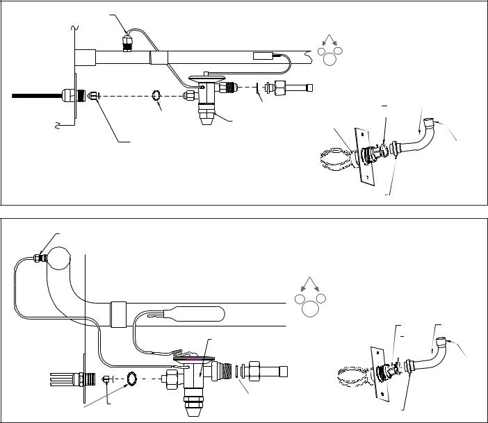
EXPANSION VALVE KITS
1/4 FLARE CONNECTION |
|
|
For Applications requiring |
||
|
|
a field installed access fitting |
|||
|
|
BULB TO BE LOCATED |
|||
|
|
AT 10 OR 2 O'CLOCK |
|||
SUCTION LINE |
BULB |
|
|
|
|
EVAPORATOR COIL |
|
|
|
|
|
|
SEAL SUPPLIED W/ KIT |
|
PISTON |
TAILPIECE |
|
|
|
|
|
||
SEAL SUPPLIED W/ KIT |
|
DISTRIBUTOR |
SEAL |
|
|
|
EXPANSION VALVE |
|
|||
|
|
BODY |
|
|
|
REMOVE BEFORE INSTALLING EXPANSION VALVE |
|
|
|
3/8"- |
|
|
|
|
|
|
|
|
|
|
|
|
SWEAT |
|
|
|
7/8" NUT |
|
|
1/4' FLARE |
|
|
For Applications not requiring |
||
CONNECTION |
|
|
a field installed access fitting |
||
|
|
|
|||
|
|
|
BULB TO BE LOCATED |
|
|
|
|
|
AT 10 OR 2 O'CLOCK |
|
|
|
BULB |
SUCTION LINE |
|
|
|
|
|
|
|
PISTON |
TAILPIECE |
EVAPORATOR COIL |
|
EXPANSION VALVE |
DISTRIBUTOR |
SEAL |
|
|
|
|
|||
|
|
BODY |
|
|
|
|
|
|
|
|
|
|
|
|
|
|
3/8"- |
|
|
|
|
|
SWEAT |
|
REMOVE BEFORE |
SEAL SUPPLIED W/ KIT |
|
|
|
SEAL SUPPLIED W/ KIT |
INSTALLING |
|
7/8" NUT |
|
|
EXPANSION VALVE |
|
|
|
||
|
|
|
|
|
|
EXPANSION VALVE KITS FOR AIR CONDITIONING-ONLY APPLICATIONS
Kit Number |
Use With |
Description |
|
|
|
XVB18-36C |
ARUF018 to ARUF036 |
20% Bleed Valve |
|
|
|
XVB42-60C |
ARUF042 to ARUF060 |
20% Bleed Valve |
|
|
|
XV18-36C |
ARUF018 to ARUF 036 |
Non-Bleed Valve |
|
|
|
XV42-60C |
ARUF042 to ARUF061 |
Non-Bleed Valve |
|
|
|
15
ACCESSORIES
PISTONKITCHART
OUTDOOR |
INDOOR UNIT BTU's |
|
INDOOR |
PISTON |
UNIT |
|
PISTON |
KIT |
|
|
|
|
SIZE |
PART NO. |
CKL18-1* |
18000 |
|
.052 |
(2) |
|
24000 |
|
.052 |
B1789852 (3) |
|
29000 |
|
.052 |
B1789852 (3) |
|
31000 |
|
.055 |
B1789855 (3) |
|
32000 |
|
.055 |
B1789855 (3) |
|
36000 |
|
.055 |
B1789855 (3) |
|
AH18 |
|
.049 |
(2) |
|
AE(R)24 |
|
.055 |
B1789855 (3) |
CKL24-1* |
24000 |
|
.059 |
(2) |
|
29000 |
|
.059 |
(2) |
|
30000 |
|
.059 |
B1789859 (3) |
|
31000 |
|
.062 |
B1789862 (3) |
|
32000 |
|
.062 |
B1789862 (3) |
|
36000 |
|
.062 |
B1789862 (3) |
|
AE(R)24 |
|
.062 |
(2) |
CKL30-1* |
24000 |
|
.065 |
(3) |
|
29000 |
|
.065 |
(4) |
|
30000 |
|
.065 |
(2) |
|
31000 |
|
.065 |
B1789865 (3) |
|
32000 |
|
.065 |
B1789865 (3) |
|
36000 |
|
.065 |
B1789865 (3) |
|
42000 |
|
.068 |
B1789868 (3) |
|
49000 |
|
.068 |
B1789868 (3) |
|
AE(R)30 |
|
.068 |
(2) |
|
AE(R)36 |
|
.068 |
B1789868 (3) |
CKL36-1* |
35000 |
|
.071 |
(2) |
|
36000 |
|
.071 |
(2) |
|
42000 |
|
.073 |
B1789873 (3) |
|
49000 |
|
.073 |
B1789873 (3) |
|
AE(R)36 |
|
.074 |
(2) |
CKL42-1* |
42000 |
|
.078 |
(2) |
|
47000 |
|
.078 |
B1789878 (3) |
|
48000 |
|
.078 |
B1789878 (3) |
|
49000 |
|
.078 |
B1789878 (3) |
|
60000 |
|
.078 |
B1789878 (3) |
|
AE(R)48 |
|
.082 |
(2) |
CKL49-1*/3* |
47000 |
|
.082 |
(2) |
|
48000 |
|
.082 |
(2) |
|
49000 |
|
.082 |
(2) |
|
59000 |
|
.082 |
B1789882 (1) |
|
60000 |
|
.082 |
B1789882 (1) |
|
61000 |
|
.082 |
B1789882 (1) |
CKL60-1*/3* |
60000 |
|
.090 |
(2) |
|
61000 |
|
.090 |
(2) |
|
62000 |
|
.090 |
(2) |
|
AE(R)60 |
|
.090 |
(2) |
CKL62-1* |
59000 |
|
.093 |
B1789893 (1) |
|
60000 |
|
.093 |
B1789893 (1) |
|
61000 |
|
.093 |
B1789893 (1) |
|
62000 |
|
.093 |
B1789893 (1) |
|
AE(R)60 |
|
.093 |
B1789893 (1) |
CLJ18-1* |
18000 |
|
.055 |
B1789855 (1) |
|
24000 |
|
.055 |
B1789855 (1) |
|
29000 |
|
.055 |
B1789855 (1) |
|
30000 |
|
.055 |
B1789855 (1) |
|
31000 |
|
.055 |
B1789855 (1) |
|
32000 |
|
.055 |
B1789855 (1) |
|
36000 |
|
.055 |
B1789855 (1) |
|
AH18 |
|
.052 |
B1789852 (3) |
|
AE(R)24 |
|
.055 |
B1789855 (1) |
CLJ24-1* |
24000 |
|
.057 |
B1789857 (1) |
|
29000 |
|
.057 |
B1789857 (1) |
|
30000 |
|
.057 |
B1789857 (1) |
|
31000 |
|
.057 |
B1789857 (1) |
|
32000 |
|
.057 |
B1789857 (1) |
|
36000 |
|
.057 |
B1789857 (1) |
|
AE(R)24 |
|
.057 |
B1789857 (1) |
CLJ30-1* |
30000 |
|
.065 |
(2) |
|
31000 |
|
.065 |
B1789865 (1) |
|
32000 |
|
.065 |
B1789865 (1) |
|
36000 |
|
.065 |
B1789865 (1) |
|
AE(R)30 |
|
.065 |
B1789865 (1) |
|
AE(R)36 |
|
.065 |
B1789865 (1) |
(*) SIGNIFIES UNIT REVISION. |
|
|
||
(1) PISTON SUPPLIED WITH THE OUTDOOR UNIT. |
|
|
||
(2) PISTON SUPPLIED WITH THE INDOOR UNIT. |
|
|
||
(3) PURCHASE PISTON KIT FROM DISTRIBUTOR. |
|
|
||
(4) B1789865 PISTON PROVIDED IN THE INDOOR UNIT. |
|
. |
||
|
|
|
|
|
16
|
|
|
|
OUTDOOR |
INDOOR UNIT BTU's |
INDOOR |
PISTON |
UNIT |
|
PISTON |
KIT |
|
|
SIZE |
PART NO. |
CLJ36-1* |
36000 |
.071 |
(2) |
|
42000 |
.073 |
B1789873 (1) |
|
47000 |
.073 |
B1789873 (1) |
|
49000 |
.073 |
B1789873 (1) |
|
AE(R)36 |
.074 |
(2) |
CLJ42-1* |
42000 |
.078 |
(2) |
|
48000 |
.078 |
B1789878 (1) |
|
49000 |
.078 |
B1789878 (1) |
|
59000 |
.078 |
B1789878 (1) |
|
60000 |
.078 |
B1789878 (1) |
|
AE(R)48 |
.078 |
B1789878 (1) |
CLJ48-1* |
48000 |
.082 |
(2) |
|
49000 |
.082 |
(2) |
|
59000 |
.082 |
B1789882 (1) |
|
60000 |
.082 |
B1789882 (1) |
|
61000 |
.082 |
B1789882 (1) |
|
62000 |
.082 |
B1789882 (1) |
|
AE(R)48 |
.082 |
(2) |
CLJ60-1* |
59000 |
.093 |
B1789893 (1) |
|
60000 |
.093 |
B1789893 (1) |
|
61000 |
.093 |
B1789893 (1) |
|
62000 |
.093 |
B1789893 (1) |
|
AE(R)60 |
.093 |
B1789893 (1) |
CLT24-1*/CRT24-1* |
24000 |
.055 |
B1789855 (1) |
|
29000 |
.055 |
B1789855 (1) |
|
31000 |
.055 |
B1789855 (1) |
|
32000 |
.055 |
B1789855 (1) |
|
36000 |
.055 |
B1789855 (1) |
|
42000 |
.055 |
B1789855 (1) |
|
49000 |
.055 |
B1789855 (1) |
|
AE(R)24 |
.055 |
B1789855 (1) |
CLT30-1*/CRT30-1* |
30000 |
.065 |
(2) |
|
32000 |
.065 |
B1789865 (1) |
|
36000 |
.065 |
B1789865 (1) |
|
42000 |
.065 |
B1789865 (1) |
|
49000 |
.065 |
B1789865 (1) |
|
AE(R)36 |
.065 |
B1789865 (1) |
CLT36-1*/CRT36-1* |
47000 |
.074 |
B1789874 (1) |
|
48000 |
.074 |
B1789874 (1) |
|
49000 |
.074 |
B1789874 (1) |
|
60000 |
.074 |
B1789874 (1) |
|
AE(R)36 |
.074 |
(2) |
CLT42-1*/CRT42-1* |
42000 |
.078 |
(2) |
|
48000 |
.078 |
B1789878 (3) |
|
49000 |
.078 |
B1789878 (3) |
|
61000 |
.080 |
B1789880 (1) |
|
62000 |
.080 |
B1789880 (1) |
|
AE(R)48 |
.082 |
(2) |
CLT48-1*/CRT48-1* |
48000 |
.082 |
(2) |
|
49000 |
.082 |
(2) |
|
60000 |
.082 |
B1789882 (1) |
|
61000 |
.082 |
B1789882 (1) |
|
62000 |
.082 |
B1789882 (1) |
|
AE(R)48 |
.082 |
(2) |
CLT60-1*/CRT60-1* |
60000 |
.088 |
B1789888 (1) |
|
61000 |
.088 |
B1789888 (1) |
|
62000 |
.088 |
B1789888 (1) |
|
AE(R)60 |
.088 |
B1789888 (1) |
CLQ24-1* |
31000 |
.059 |
B1789859 (1) |
|
32000 |
.059 |
B1789859 (1) |
|
36000 |
.059 |
B1789859 (1) |
|
42000 |
.059 |
B1789859 (1) |
|
47000 |
.059 |
B1789859 (1) |
|
49000 |
.059 |
B1789859 (1) |
|
AE(R)24 |
.059 |
B1789859 (1) |
CLQ30-1* |
31000 |
.065 |
B1789865 (1) |
|
32000 |
.065 |
B1789865 (1) |
|
36000 |
.065 |
B1789865 (1) |
|
60000 |
.065 |
B1789865 (1) |
|
61000 |
.065 |
B1789865 (1) |
|
62000 |
.065 |
B1789865 (1) |
|
AE(R)36 |
.065 |
B1789865 (1) |
CLQ36-1* |
49000 |
.073 |
B1789873(1) |
|
60000 |
.073 |
B1789873(1) |
|
61000 |
.073 |
B1789873(1) |
|
62000 |
.073 |
B1789873(1) |
|
AE(R)36 |
.073 |
B1789873(1) |
CLQ42-1* |
49000 |
.080 |
B1789880 (1) |
|
|
. |
7 |
|
61000 |
.080 |
B1789880 (1) |
|
62000 |
.080 |
B1789880 (1) |
|
AE(R)48 |
.080 |
B1789880 (1) |
CLQ48-1* |
49000 |
.082 |
(2) |
|
60000 |
.082 |
B1789882 (1) |
|
61000 |
.082 |
B1789882 (1) |
|
62000 |
.082 |
B1789882 (1) |
|
AE(R)48 |
.082 |
(2) |
CLQ60-1* |
60000 |
.090 |
(2) |
|
61000 |
.090 |
(2) |
|
62000 |
.090 |
(2) |
|
AE(R)60 |
.090 |
(2) |
ACCESSORIES
OUTDOOR |
INDOOR UNIT BTU's |
INDOOR |
PISTON |
UNIT |
PISTON |
KIT |
|
|
|
SIZE |
PART NO. |
CPLE18-1* |
18000 |
.052 |
(2) |
|
24000 |
.052 |
B1789852 (3) |
|
29000 |
.052 |
B1789852 (3) |
|
36000 |
.052 |
B1789852 (3) |
CPLE24-1* |
24000 |
.059 |
(2) |
|
29000 |
.059 |
(2) |
|
30000 |
.059 |
B1789859 (3) |
|
31000 |
.059 |
B1789859 (3) |
|
32000 |
.059 |
B1789859 (3) |
|
36000 |
.059 |
B1789859 (3) |
CPLE30-1* |
29000 |
.065 |
B1789865 (3) |
|
30000 |
.065 |
(2) |
|
31000 |
.068 |
(2) |
|
32000 |
.068 |
(2) |
|
36000 |
.068 |
B1789868 (3) |
|
48000 |
.068 |
B1789868 (3) |
CPLE36-1* |
35000 |
.073 |
B1789873 (1) |
|
36000 |
.073 |
B1789873 (1) |
|
42000 |
.073 |
B1789873 (1) |
|
47000 |
.073 |
B1789873 (1) |
|
48000 |
.073 |
B1789873 (1) |
|
49000 |
.073 |
B1789873 (1) |
CPLE42-1* |
42000 |
.078 |
(2) |
|
47000 |
.078 |
B1789878 (3) |
|
48000 |
.078 |
B1789878 (3) |
|
49000 |
.078 |
B1789878 (3) |
CPLE48-1* |
47000 |
.082 |
(2) |
|
49000 |
.082 |
(2) |
|
59000 |
.082 |
B1789882 (3) |
|
60000 |
.082 |
B1789882 (3) |
|
61000 |
.082 |
B1789882 (3) |
|
62000 |
.082 |
B1789882 (3) |
CPLE60-1*/3* |
61000 |
.092 |
B1789892 (1) |
CPLJ18-1* |
18000 |
.052 |
(2) |
|
24000 |
.055 |
B1789855 (1) |
|
32000 |
.055 |
B1789855 (1) |
|
36000 |
.055 |
B1789855 (1) |
|
AE(R)24 |
.055 |
B1789855 (1) |
CPLJ24-1* |
24000 |
.059 |
(2) |
|
30000 |
.059 |
B1789859 (1) |
|
31000 |
.059 |
B1789859 (1) |
|
32000 |
.059 |
B1789859 (1) |
|
36000 |
.059 |
B1789859 (1) |
|
42000 |
.059 |
B1789859 (1) |
|
AE(R)24 |
.059 |
B1789859 (1) |
CPLJ30-1* |
30000 |
.065 |
(2) |
|
32000 |
.068 |
(2) |
|
36000 |
.068 |
B1789868 (1) |
|
42000 |
.068 |
B1789868 (1) |
|
AE(R)30 |
.068 |
(2) |
|
AE(R)36 |
.068 |
B1789868 (1) |
CPLJ36-1* |
36000 |
.071 |
(2) |
|
42000 |
.074 |
B1789874 (1) |
|
49000 |
.074 |
B1789874 (1) |
|
AE(R)36 |
.074 |
(2) |
CPLJ42-1* |
42000 |
.078 |
(2) |
|
49000 |
.078 |
B1789878 (1) |
|
60000 |
.078 |
B1789878 (1) |
|
61000 |
.078 |
B1789878 (1) |
|
AE(R)48 |
.078 |
B1789878 (1) |
(*) SIGNIFIES UNIT REVISION.
(1) PISTON SUPPLIED WITH THE OUTDOOR UNIT.
(2) PISTON SUPPLIED WITH THE INDOOR UNIT. .
(4) B1789865 PISTON PROVIDED IN THE INDOOR UNIT.
(5) PISTON PROVIDED IN THE OUTDOOR UNIT LIQUID LINE SERVICE VALVE.
OUTDOOR |
INDOOR UNIT BTU's |
INDOOR |
PISTON |
UNIT |
PISTON |
KIT |
|
|
|
SIZE |
PART NO. |
CPLJ48-1* |
48000 |
.082 |
(2) |
|
49000 |
.084 |
B1789884 (1) |
|
60000 |
.084 |
B1789884 (1) |
|
61000 |
.084 |
B1789884 (1) |
|
AE(R)48 |
.084 |
B1789884 (1) |
CPLJ60-1* |
60000 |
.090 |
(2) |
|
61000 |
.090 |
(2) |
|
62000 |
.090 |
(2) |
|
AE(R)60 |
.090 |
(2) |
CPLT24-1*/CPRT24-1* |
32000 |
.062 |
B1789862 (1) |
|
36000 |
.062 |
B1789862 (1) |
|
42000 |
.062 |
B1789862 (1) |
|
AE(R)24 |
.062 |
(2) |
CPLT30-1*/CPRT30-1* |
32000 |
.071 |
B1789871 (1) |
|
36000 |
.071 |
(2) |
|
42000 |
.071 |
B1789871 (1) |
|
AE(R)30 |
.071 |
B1789871 (1) |
|
AE(R)36 |
.071 |
B1789871 (1) |
CPLT36-1*/CPRT36-1* |
48000 |
.073 |
B1789873 (1) |
|
49000 |
.073 |
B1789873 (1) |
|
60000 |
.073 |
B1789873 (1) |
|
AE(R)36 |
.073 |
B1789873 (1) |
CPLT42-1*/CPRT42-1* |
49000 |
.078 |
B1789878 (1) |
|
60000 |
.078 |
B1789878 (1) |
|
61000 |
.078 |
B1789878 (1) |
|
AE(R)48 |
.078 |
B1789878 (1) |
CPLT48-1*/CPRT48-1* |
61000 |
.084 |
B1789884 (1) |
|
AE(R)48 |
.084 |
B1789884 (1) |
CPLT60-1*/CPRT60-1* |
61000 |
.092 |
B1789892 (1) |
|
AE(R)60 |
.092 |
B1789892 (1) |
|
EXPORT UNITS |
|
|
|
|
|
|
CKF36-2L* |
36000 |
.067 |
(2) |
CKF36-5L* |
36000 |
.067 |
(2) |
CKF48-5L* |
48000 |
.076 |
(2) |
CKF60-5L* |
60000 |
.089 |
(2) |
CKF70-5L* |
60000 |
.089 |
(2) |
CPKF24-2L* |
24000 |
.059 |
(2) |
CPKF36-2L* |
36000 |
.067 |
(2) |
CPKF36-5L* |
36000 |
.067 |
(2) |
CPKF36-2L* |
48000 |
.067 |
B1789867 (3) |
CPKF36-5L* |
48000 |
.067 |
B1789867 (3) |
CPKF42-5L* |
48000 |
.073 |
B1789873 (3) |
CPKF48-2L* |
48000 |
.076 |
(2) |
CPKF48-5L* |
48000 |
.076 |
(2) |
CPKF60-5L* |
60000 |
.089 |
(2) |
CPKF61-5L* |
60000 |
.092 |
B1789892 (3) |
|
MINI SPLIT UNITS |
|
|
|
|
|
|
HDC12-1* |
12000 |
.045 |
(5) |
|
18000 |
.045 |
(5) |
HDC18-1* |
18000 |
.052 |
(5) |
|
24000 |
.052 |
(5) |
HDC24-1* |
24000 |
.055 |
(5) |
HDP12-1* |
12000 |
.045 |
(5) |
|
18000 |
.045 |
(5) |
HDP18-1* |
18000 |
.052 |
(5) |
|
24000 |
.052 |
(5) |
HDP24-1* |
24000 |
.055 |
(5) |
|
THROUGH THE WALL UNITS |
|
|
|
|
|
|
TWC18-1* |
18000 |
.052 |
(2) |
TWC24-1* |
24000 |
.059 |
(2) |
|
30000 |
.059 |
B1789859 (3) |
TWCR30-1* |
36000 |
.062 |
B1789862 (1) |

 WARNING
It is essential that indoor and outdoor units be properly matched. Failure to follow these instructions or to properly match evaporators and condensors can result in unit damage, property damage and/or personal injury. No warranty will be honored for mix-matched systems that fail to adhere to these instructions.
17
ACCESSORIES
FP-01
FREEZETHERMOSTAT
KIT
Wire Nut
Y
lack |
k |
|
B |
|
|
|
c |
|
|
a |
|
|
Bl |
Wire Nut |
|
|
Install Line
Thermostat
Here
Y
Install Line |
|
|
Thermostat |
|
|
Here |
|
|
|
Wire Nut |
|
Bl |
|
|
a |
|
Y |
ck |
||
B |
|
|
l |
|
|
a |
|
|
c |
|
|
Wire Nut |
k |
Y |
|
||
|
|
|
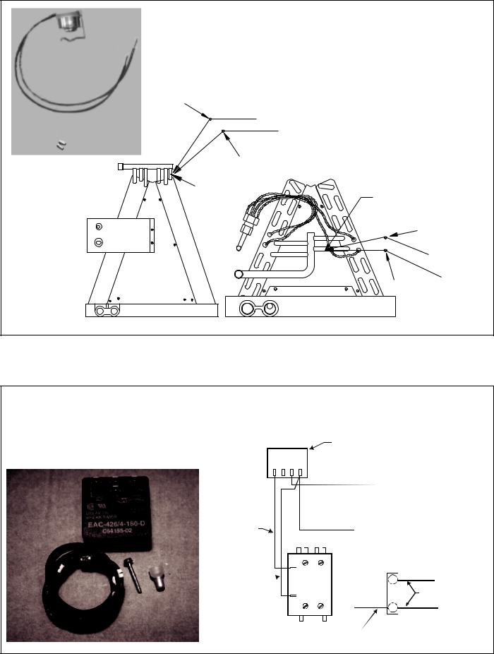
ASC01A
ANTI-SHORT-CYCLECONTROLKIT
SHORT CYCLE
Y1 R1  PROTECTOR
Y2 R2
|
|
|
|
|
|
|
|
|
|
|
|
|
|
|
YELLOW 1 |
|
|
|
|
|
|
||||||||
|
|
|
|
|
|
|||||||||
|
|
|
|
CONTACTOR |
|
|
|
|
|
|||||
|
|
|
|
|
|
|
T2 |
T1 |
|
|
|
|
|
|
|
|
|
|
|
|
|
|
|
|
Y |
|
|||
BLACK 1 |
|
|
|
|
THERMOSTAT |
|||||||||
|
|
|
|
|||||||||||
|
|
|
|
|
|
|
L2 L1 |
|
|
|
|
|||
|
|
|
|
|
|
|
|
|
|
C |
WIRE |
|||
|
|
|
|
|
|
|
|
|
|
|
|
|
|
|
|
|
|
|
|
|
|
|
|
|
|
UNIT |
|||
|
|
|
|
|
|
|
|
|
BLACK 1 |
TERMINAL |
||||
|
|
|
|
|
|
|
|
|
|
|
BOARD |
|||
18
ACCESSORIES
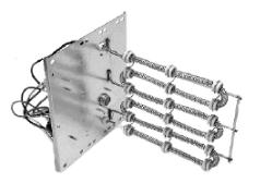
HEATER KIT APPLICATION OPTIONS
|
|
AURF018-00A-1/-1A |
|
AURF024-00A-1/-1A |
AURF030-00A-1/-1A |
AURF032-00A-1B/-1C |
AURF036-00A-1/-1A |
AURF042-00A-1/-1A |
AURF042-00A-1B |
|
AURF042-00A-1/-1A |
AURF049-00A-1/-1A |
AURF049-00A-1B |
AURF060-00A-1/-1A |
AURF061-00A-1/-1A |
AURF061-00A-1B |
|
|
|
|
|
|
|
|
|
|
|
|
|
|
|
|
|
|
HKR-03 |
X |
|
X |
X |
X |
X |
X |
X |
|
X |
X |
X |
X |
X |
X |
|
|
|
|
|
|
|
|
|
|
|
|
|
|
|
|
|
|
HKR-05C |
X |
|
X |
X |
X |
X |
X |
X |
|
X |
X |
X |
X |
X |
X |
|
HKR-06 |
X |
|
X |
X |
X |
X |
X |
X |
|
X |
X |
X |
X |
X |
X |
|
|
|
|
|
|
|
|
|
|
|
|
|
|
|
|
|
|
HKR-08C |
X |
|
X |
X |
X |
X |
X |
X |
|
X |
X |
X |
X |
X |
X |
|
HKR-10C |
|
|
X |
X |
X+ |
X |
X |
X |
|
X |
X |
X |
X |
X |
X |
|
HKR-15C |
|
|
|
X |
X† |
X |
X |
X |
|
X |
X |
X |
X |
X |
X |
|
HKR-20C |
|
|
|
|
|
X |
X |
Xƒ |
|
X |
X |
X |
X |
X |
X |
|
HKR-21C |
|
|
|
|
|
X |
X |
Xƒ |
|
X |
X |
X |
X |
X |
X |
|
HKR3-15* |
|
|
|
|
|
X |
X |
X |
|
X |
X |
X |
X |
X |
X |
|
HKR3-20* |
|
|
|
|
|
X |
X |
Xƒ |
|
X |
X |
X |
X |
X |
X |
C |
Circuit breakers optional. |
|
|
|
|
|
|
|
|
|
|
|
|
|
||
* Heat Kit requires 3-phase power supply. |
|
|
|
|
|
|
|
|
|
|
|
|||||
+ When using a 10 kW heat kit, this air handler must either be in medium or high speed |
|
|
|
|
|
|
||||||||||
† When using a 15 kW heat kit, this air handler must be on high speed. |
|
|
|
|
|
|
|
|
||||||||
ƒ |
When using a 20 kW heat kit, this air handler must be on high speed |
|
|
|
|
|
|
|
|
|||||||
HEATER KIT APPLICATION OPTIONS
|
AER24-1 |
AER30-1 |
AER36-01 |
AER48-1 |
AER60-1 |
|
|
|
|
|
|
HKR-03 |
|
|
|
|
|
|
|
|
|
|
|
HKR-05C |
X |
X |
|
|
|
HKR-06 |
|
|
|
|
|
|
|
|
|
|
|
HKR-08C |
X |
X |
X |
|
|
HKR-10C |
X |
X |
X |
X |
X |
HKR-15C |
|
|
X |
X |
X |
HKR-20C |
|
|
|
|
X |
HKR-21C |
|
|
|
|
X |
C Circuit Breakers optional.
HKRSERIESELECTRICHEATKITS
19

PRODUCT SPECIFICATIONS |
CKL |
Specifications
|
Nominal |
|
Service Valve |
Compressor |
Condenser |
Shipping |
||||
|
Cooling |
|
|
Fan |
||||||
Model |
|
|
|
|
|
|
Weight |
|||
Capacity |
|
|
Connection |
|
|
|
|
|
||
|
Liquid |
Suction |
RLA |
LRA |
HP |
|
FLA |
(pounds) |
||
|
(BTUH) |
Type |
|
|||||||
|
|
|
|
|
|
|
|
|
||
CKL18-1L |
18,000 |
3/8” |
3/4” |
Sweat |
8.5 |
49 |
1/6 |
|
1.3 |
125 |
|
|
|
|
|
|
|
|
|
|
|
CKL24-1L |
24,000 |
3/8” |
3/4” |
Sweat |
9.8 |
56 |
1/6 |
|
1.3 |
127 |
|
|
|
|
|
|
|
|
|
|
|
CKL24-1M |
24,000 |
3/8” |
3/4” |
Sweat |
12.1 |
57 |
1/6 |
|
1.3 |
127 |
|
|
|
|
|
|
|
|
|
|
|
CKL30-1L |
29,000 |
3/8” |
3/4” |
Sweat |
13.7 |
75 |
1/6 |
|
1.3 |
130 |
|
|
|
|
|
|
|
|
|
|
|
CKL36-1L |
35,000 |
3/8” |
3/4” |
Sweat |
17.2 |
96 |
1/6 |
|
1.3 |
152 |
|
|
|
|
|
|
|
|
|
|
|
CKL42-1L |
41,000 |
3/8” |
7/8” |
Sweat |
17.2 |
105 |
1/6 |
|
1.3 |
160 |
|
|
|
|
|
|
|
|
|
|
|
CKL49-1L |
47,000 |
3/8” |
7/8” |
Sweat |
18.3 |
102 |
1/4 |
|
1.8 |
176 |
|
|
|
|
|
|
|
|
|
|
|
CKL60-1L |
57,000 |
3/8” |
7/8” |
Sweat |
25 |
150 |
1/4 |
|
1.8 |
208 |
|
|
|
|
|
|
|
|
|
|
|
CKL62-1L |
62,000 |
3/8” |
7/8” |
Sweat |
27.1 |
144 |
1/3 |
|
2.3 |
258 |
|
|
|
|
|
|
|
|
|
|
|
CKL36-3L |
35,000 |
3/8” |
3/4” |
Sweat |
10.3 |
75 |
1/6 |
|
1.3 |
142 |
|
|
|
|
|
|
|
|
|
|
|
CKL49-3L |
47,000 |
3/8” |
7/8” |
Sweat |
12.6 |
91 |
1/4 |
|
1.8 |
176 |
|
|
|
|
|
|
|
|
|
|
|
CKL60-3L |
57,000 |
3/8” |
7/8” |
Sweat |
15.4 |
124 |
1/4 |
|
1.8 |
208 |
|
|
|
|
|
|
|
|
|
|
|
CKL60-4L |
57,000 |
3/8” |
7/8” |
Sweat |
7.4 |
59.6 |
1/4 |
|
0.8 |
208 |
|
|
|
|
|
|
|
|
|
|
|
CKL62-1L |
62,000 |
3/8” |
7/8” |
Sweat |
27.1 |
144 |
1/3 |
|
2.3 |
258 |
|
|
|
|
|
|
|
|
|
|
|
Electrical Data
|
Minimum Circuit |
Maximum |
|
|
|
|
Model |
Overcurrent |
Voltage-Phase |
Minimum Volts |
Maximum Volts |
||
Ampacity |
||||||
|
Protection |
|
|
|
||
|
|
|
|
|
||
CKL18-1L |
11.9 |
20 amps |
208/230-1 |
197 |
253 |
|
|
|
|
|
|
|
|
CKL24-1L |
13.6 |
20 amps |
208/230-1 |
197 |
253 |
|
|
|
|
|
|
|
|
CKL24-1M |
16.4 |
20 amps |
208/230-1 |
197 |
253 |
|
|
|
|
|
|
|
|
CKL30-1L |
18.4 |
30 amps |
208/230-1 |
197 |
253 |
|
|
|
|
|
|
|
|
CKL36-1L |
22.8 |
40 amps |
208/230-1 |
197 |
253 |
|
|
|
|
|
|
|
|
CKL42-1L |
22.8 |
40 amps |
208/230-1 |
197 |
253 |
|
|
|
|
|
|
|
|
CKL49-1L |
24.7 |
40 amps |
208/230-1 |
197 |
253 |
|
|
|
|
|
|
|
|
CKL60-1L |
33.1 |
50 amps |
208/230-1 |
197 |
253 |
|
|
|
|
|
|
|
|
CKL62-1L |
36.1 |
60 amps |
208/230-1 |
197 |
253 |
|
|
|
|
|
|
|
|
CKL36-3L |
14.2 |
20 amps |
208/230-3 |
197 |
253 |
|
|
|
|
|
|
|
|
CKL49-3L |
17.6 |
30 amps |
208/230-3 |
197 |
253 |
|
|
|
|
|
|
|
|
CKL60-3L |
21.1 |
30 amps |
208/230-3 |
197 |
253 |
|
|
|
|
|
|
|
|
CKL60-4L |
10.1 |
15 amps |
460-3 |
414 |
506 |
|
|
|
|
|
|
|
|
CKL62-1L |
36.1 |
60 amps |
208/230-1 |
197 |
253 |
|
|
|
|
|
|
|
1)Wire size should be determined in accordance with National Electrical Codes. Extensive wire runs will require larger wire sizes.
2)May use fuses or HACR type Circuit Breakers of the same size as noted.
20
CKL |
PRODUCT SPECIFICATIONS |
Dimensions
W D
H
|
1 -1/8" DIA. POWER |
ADDITIONAL 1 -1/2" |
7/8" DIA. CONTROL |
ELEVATED CHANNEL |
|
FORMED INTO BOTTOM PAN |
|
LIQUID CONN. |
SUCTION CONN. |
Model |
Width |
Depth |
Height |
|
|
|
|
CKL18-1L |
23” |
23” |
24” |
|
|
|
|
CKL24-1L |
23” |
23” |
24” |
|
|
|
|
CKL24-1M |
23” |
23” |
24” |
|
|
|
|
CKL30-1L |
23” |
23” |
24” |
|
|
|
|
CKL36-1L |
23” |
23” |
29” |
|
|
|
|
CKL42-1L |
23” |
23” |
31½” |
|
|
|
|
CKL49-1L |
29” |
29” |
29” |
|
|
|
|
CKL60-1L |
29” |
29” |
31½” |
|
|
|
|
CKL62-1L |
29” |
29” |
39” |
|
|
|
|
CKL36-3L |
23” |
23” |
26½” |
|
|
|
|
CKL49-3L |
29” |
29” |
29” |
|
|
|
|
CKL60-3L |
29” |
29” |
31½” |
|
|
|
|
CKL60-4L |
29” |
29” |
31½” |
|
|
|
|
21

PRODUCT SPECIFICATIONS |
CKL |
Performance Ratings
Condenser |
Evaporator Model |
Total BTUH |
Sensible BTUH |
SEER |
EER |
ARI Ref. # |
Decibel |
|
|
AC18-XX |
17,000 |
12,410 |
10.00 |
9.00 |
467525 |
76 |
|
|
ACHP1819-1 |
16,800 |
12,264 |
10.00 |
9.00 |
467533 |
76 |
|
|
AEPT030-00*-1* |
18,000 |
13,140 |
11.00 |
9.80 |
517544 |
76 |
|
|
AH18 |
17,400 |
12,702 |
10.00 |
9.00 |
467531 |
76 |
|
|
ARPF024-00B-1* |
17,400 |
12,702 |
10.00 |
9.00 |
517514 |
76 |
|
|
ARPT024-00*-1* |
17,400 |
12,702 |
10.00 |
9.00 |
517529 |
76 |
|
|
ARPT032-00*-1* |
18,000 |
13,140 |
10.50 |
9.50 |
517511 |
76 |
|
|
ARUF018-00*-1* |
17,000 |
12,410 |
10.00 |
9.00 |
517512 |
76 |
|
|
ARUF024-00*-1* |
17,400 |
12,702 |
10.00 |
9.00 |
517498 |
76 |
|
CKL18-1* |
ARUF032-00*-1* |
18,000 |
13,140 |
10.50 |
9.50 |
517497 |
76 |
|
AWB18-XX |
16,800 |
12,264 |
10.00 |
9.00 |
467564 |
76 |
||
|
||||||||
|
AWB24-XX |
17,000 |
12,325 |
10.00 |
9.00 |
467560 |
76 |
|
|
CA*F018*2*+EEP |
17,000 |
12,325 |
10.00 |
9.00 |
503271 |
76 |
|
|
CA*F024*2*+EEP |
17,400 |
12,615 |
10.00 |
9.00 |
503272 |
76 |
|
|
CA*F030*2*+EEP |
18,000 |
13,050 |
10.50 |
9.50 |
503273 |
76 |
|
|
CHPF024A2*+EEP |
17,400 |
12,615 |
10.00 |
9.00 |
503276 |
76 |
|
|
CHPF025B2*+EEP |
17,400 |
12,615 |
10.00 |
9.00 |
530822 |
76 |
|
|
CHPF030A2*+EEP |
18,000 |
13,050 |
10.50 |
9.50 |
503277 |
76 |
|
|
H24F+EEP |
17,400 |
12,528 |
10.00 |
9.00 |
466994 |
76 |
|
|
H36F+EEP |
18,000 |
12,960 |
10.50 |
9.50 |
466980 |
76 |
|
|
AC24-XX |
23,200 |
17,052 |
10.00 |
9.00 |
467561 |
75 |
|
|
ACHP2423-1 |
23,200 |
17,052 |
10.00 |
9.00 |
467556 |
75 |
|
|
AEPT030-00*-1* |
24,000 |
17,640 |
11.00 |
9.80 |
517545 |
75 |
|
|
AH24 |
23,200 |
17,052 |
10.00 |
9.00 |
467559 |
75 |
|
|
ARPF024-00B-1* |
23,000 |
16,905 |
10.00 |
9.00 |
517509 |
75 |
|
|
ARPT024-00*-1* |
23,000 |
16,905 |
10.00 |
9.00 |
517501 |
75 |
|
|
ARPT032-00*-1* |
24,000 |
17,640 |
10.50 |
9.50 |
517495 |
75 |
|
|
ARUF024-00*-1* |
23,000 |
16,905 |
10.00 |
9.00 |
517507 |
75 |
|
CKL24-1* |
ARUF032-00*-1* |
24,000 |
17,640 |
10.50 |
9.50 |
517521 |
75 |
|
AWB24-XX |
23,200 |
17,052 |
10.00 |
9.00 |
467568 |
75 |
||
|
||||||||
|
CA*F024*2*+EEP |
23,000 |
16,905 |
10.00 |
9.00 |
503280 |
75 |
|
|
CA*F030*2*+EEP |
24,000 |
17,640 |
10.50 |
9.50 |
503281 |
75 |
|
|
CA*F036*2*+EEP |
24,000 |
17,640 |
10.50 |
9.50 |
503282 |
75 |
|
|
CHPF024A2*+EEP |
23,000 |
16,790 |
10.00 |
9.00 |
503285 |
75 |
|
|
CHPF025B2*+EEP |
23,000 |
16,790 |
10.00 |
9.00 |
530824 |
75 |
|
|
CHPF030A2*+EEP |
24,000 |
17,520 |
10.50 |
9.50 |
503286 |
75 |
|
|
H24F+EEP |
23,000 |
16,675 |
10.00 |
9.00 |
467002 |
75 |
|
|
H36F+EEP |
24,000 |
17,400 |
10.50 |
9.50 |
467008 |
75 |
(1)Seasonal Energy Effi ciency Ratio
(2)Energy Effi ciency Ratio @ 80°F/67°F Inside - 95°F
(3)When matching the outdoor unit to the indoor unit, use the piston supplied with the outdoor unit or that specifi ed on the piston kit chart supplied with the indoor unit.
(4)Note: XX of A Model Designate Electric Heat Quantity.
(5)EEP - Order from Service Dept. Part No. B13707-38 or new Solid State Board B13707-35S. Part No. B13707-38 is not interchangeable with B13707-35S.
The Goodman Gas Furnace contains the EEP cooling time delay.
22

CKL |
PRODUCT SPECIFICATIONS |
Performance Ratings (cont.)
Condenser |
Evaporator Model |
Total BTUH |
Sensible BTUH |
SEER |
EER |
ARI Ref. # |
Decibel |
|
|
AC30-XX |
28,400 |
20,590 |
10.00 |
9.00 |
467562 |
78 |
|
|
AC36-XX |
29,000 |
21,315 |
10.00 |
9.00 |
467555 |
78 |
|
|
ACHP3028-1 |
28,000 |
20,580 |
10.00 |
9.00 |
467567 |
78 |
|
|
AEPT030-00*-1* |
28,000 |
20,580 |
10.50 |
9.50 |
517526 |
78 |
|
|
AEPT036-00*-1* |
29,000 |
21,315 |
11.00 |
9.80 |
517538 |
78 |
|
|
AH30 |
28,000 |
20,580 |
10.00 |
9.00 |
467574 |
78 |
|
|
AH36 |
29,000 |
21,315 |
10.00 |
9.00 |
467588 |
78 |
|
|
ARPF036-00B-1* |
29,000 |
21,315 |
10.50 |
9.50 |
517528 |
78 |
|
|
ARPT032-00*-1* |
29,000 |
21,315 |
10.50 |
9.50 |
517515 |
78 |
|
|
ARPT036-00*-1* |
28,000 |
20,580 |
10.00 |
9.00 |
517516 |
78 |
|
CKL30-1* |
ARUF030-00*-1* |
27,200 |
19,992 |
10.00 |
9.00 |
517543 |
78 |
|
ARUF032-00*-1* |
29,000 |
21,315 |
10.50 |
9.50 |
517531 |
78 |
||
|
||||||||
|
ARUF036-00*-1* |
28,000 |
20,580 |
10.00 |
9.00 |
517502 |
78 |
|
|
AWB30-XX |
27,000 |
19,845 |
10.00 |
9.00 |
467583 |
78 |
|
|
AWB36-XX |
28,000 |
20,580 |
10.00 |
9.00 |
467577 |
78 |
|
|
CA*F030*2*+EEP |
28,600 |
21,021 |
10.00 |
9.00 |
503289 |
78 |
|
|
CA*F042*2*+EEP |
29,000 |
21,315 |
10.50 |
9.50 |
503290 |
78 |
|
|
CHPF024A2*+EEP |
27,200 |
19,992 |
10.00 |
9.00 |
503293 |
78 |
|
|
CHPF030A2*+EEP |
28,600 |
21,021 |
10.00 |
9.00 |
503294 |
78 |
|
|
CHPF036B2*+EEP |
29,000 |
21,315 |
10.50 |
9.50 |
503295 |
78 |
|
|
H36F+EEP |
28,600 |
20,878 |
10.00 |
9.00 |
467013 |
78 |
|
|
H49F+EEP |
29,000 |
21,170 |
10.50 |
9.50 |
467010 |
78 |
Condenser |
Evaporator Model |
Total BTUH |
Sensible BTUH |
SEER |
EER |
ARI Ref. # |
Decibel |
|
|
AC36-XX |
33,200 |
24,236 |
10.00 |
9.00 |
503315 |
80 |
|
|
ACHP3632-1 |
32,000 |
23,360 |
10.00 |
9.00 |
503318 |
80 |
|
|
AEPT036-00*-1* |
35,000 |
25,550 |
11.00 |
9.80 |
517535 |
80 |
|
|
AH36 |
34,400 |
25,112 |
10.00 |
9.00 |
503313 |
80 |
|
|
ARPF036-00B-1* |
33,200 |
24,236 |
10.00 |
9.00 |
517525 |
80 |
|
|
ARPT036-00*-1* |
34,000 |
24,820 |
10.00 |
9.00 |
517541 |
80 |
|
|
ARPT042-00*-1* |
35,000 |
25,550 |
10.50 |
9.50 |
517537 |
80 |
|
|
ARUF036-00*-1* |
34,000 |
24,820 |
10.00 |
9.00 |
517546 |
80 |
|
CKL36-1* |
ARUF042-00*-1* |
35,000 |
25,550 |
10.50 |
9.50 |
517524 |
80 |
|
AWB36-XX |
34,000 |
24,820 |
10.00 |
9.00 |
503320 |
80 |
||
|
||||||||
|
CA*F036*2*+EEP |
34,000 |
24,650 |
10.00 |
9.00 |
503301 |
80 |
|
|
CA*F042*2*+EEP |
35,000 |
25,375 |
10.50 |
9.50 |
503302 |
80 |
|
|
CHPF030A2*+EEP |
34,400 |
24,940 |
10.00 |
9.00 |
503307 |
80 |
|
|
CHPF036B2*+EEP |
34,000 |
24,650 |
10.00 |
9.00 |
503310 |
80 |
|
|
CHPF042B2*+EEP |
35,000 |
25,375 |
10.50 |
9.50 |
503304 |
80 |
|
|
CHPF048C2*+EEP |
35,000 |
25,375 |
10.50 |
9.50 |
530821 |
80 |
|
|
H36F+EEP |
34,000 |
24,650 |
10.00 |
9.00 |
503300 |
80 |
|
|
H49F+EEP |
35,000 |
25,375 |
10.50 |
9.50 |
503303 |
80 |
23

PRODUCT SPECIFICATIONS |
CKL |
Performance Ratings (cont.)
Condenser |
Evaporator Model |
Total BTUH |
Sensible BTUH |
SEER |
EER |
ARI Ref. # |
Decibel |
|
AC36-XX |
33,200 |
24,070 |
10.00 |
9.00 |
503345 |
80 |
|
ACHP3632-1 |
32,000 |
23,200 |
10.00 |
9.00 |
503347 |
80 |
|
AEPT036-00*-1* |
35,000 |
25,375 |
11.00 |
9.80 |
517533 |
80 |
|
AH36 |
34,400 |
24,940 |
10.00 |
9.00 |
503338 |
80 |
|
ARPF036-00B-1* |
33,200 |
24,070 |
10.00 |
9.00 |
517519 |
80 |
|
ARPT036-00*-1* |
34,000 |
24,650 |
10.00 |
9.00 |
517539 |
80 |
|
ARPT042-00*-1* |
35,000 |
25,375 |
10.50 |
9.50 |
517517 |
80 |
|
ARUF036-00*-1* |
34,000 |
24,820 |
10.00 |
9.00 |
517522 |
80 |
CKL36-3* |
ARUF042-00*-1* |
35,000 |
25,375 |
10.50 |
9.50 |
517510 |
80 |
|
AWB36-XX |
34,000 |
24,820 |
10.00 |
9.00 |
503339 |
80 |
|
CA*F036*2*+EEP |
34,000 |
24,820 |
10.00 |
9.00 |
503325 |
80 |
|
CA*F042*2*+EEP |
35,000 |
25,550 |
10.50 |
9.50 |
503330 |
80 |
|
CHPF030A2*+EEP |
34,400 |
25,112 |
10.00 |
9.00 |
503334 |
80 |
|
CHPF036B2*+EEP |
34,000 |
24,650 |
10.00 |
9.00 |
503327 |
80 |
|
CHPF042B2*+EEP |
35,000 |
25,375 |
10.50 |
9.50 |
503337 |
80 |
|
H36F+EEP |
34,000 |
24,650 |
10.00 |
9.00 |
503333 |
80 |
|
H49F+EEP |
35,000 |
25,375 |
10.50 |
9.50 |
503332 |
80 |
Condenser |
Evaporator Model |
Total BTUH |
Sensible BTUH |
SEER |
EER |
ARI Ref. # |
Decibel |
|
AEPT060-00*-1* |
41,000 |
30,400 |
11.00 |
9.80 |
517475 |
82 |
|
ARPF048-00B-1* |
41,000 |
30,400 |
10.50 |
9.50 |
517478 |
82 |
|
ARPT042-00*-1* |
40,000 |
28,000 |
10.00 |
9.00 |
517473 |
82 |
|
ARPT049-00*-1* |
41,000 |
30,400 |
10.50 |
9.50 |
517469 |
82 |
|
ARUF042-00*-1* |
40,000 |
28,000 |
10.00 |
9.00 |
517479 |
82 |
|
ARUF048-00*-1* |
40,000 |
28,000 |
10.00 |
9.00 |
517470 |
82 |
|
ARUF049-00*-1* |
41,000 |
30,400 |
10.50 |
9.50 |
517472 |
82 |
CKL42-1* |
CA*F042*2*+EEP |
39,500 |
27,650 |
10.00 |
9.00 |
503352 |
82 |
|
CA*F048*2*+EEP |
40,500 |
29,160 |
10.00 |
9.00 |
503353 |
82 |
|
CA*F060*2*+EEP |
41,000 |
30,400 |
10.50 |
9.50 |
503354 |
82 |
|
CHPF042B2*+EEP |
40,000 |
28,000 |
10.00 |
9.00 |
503357 |
82 |
|
CHPF048C2*+EEP |
40,000 |
30,400 |
10.00 |
9.00 |
530820 |
82 |
|
CHPF048D2*+EEP |
41,000 |
28,000 |
10.50 |
9.50 |
503358 |
82 |
|
H49F+EEP |
40,000 |
30,400 |
10.00 |
9.00 |
467033 |
82 |
|
H60F+EEP |
41,000 |
34,200 |
10.50 |
9.50 |
467030 |
82 |
(1)Seasonal Energy Effi ciency Ratio
(2)Energy Effi ciency Ratio @ 80°F/67°F Inside - 95°F
(3)When matching the outdoor unit to the indoor unit, use the piston supplied with the outdoor unit or that specifi ed on the piston kit chart supplied with the indoor unit.
(4)Note: XX of A Model Designate Electric Heat Quantity.
(5)EEP - Order from Service Dept. Part No. B13707-38 or new Solid State Board B13707-35S. Part No. B13707-38 is not interchangeable with B13707-35S.
The Goodman Gas Furnace contains the EEP cooling time delay.
24

CKL |
PRODUCT SPECIFICATIONS |
Performance Ratings (cont.)
Condenser |
Evaporator Model |
Total BTUH |
Sensible BTUH |
SEER |
EER |
ARI Ref. # |
Decibel |
|
|
AEPT060-00*-1* |
45,000 |
35,000 |
11.00 |
9.80 |
517486 |
80 |
|
|
ARPF048-00B-1* |
46,000 |
35,000 |
10.50 |
9.30 |
517477 |
80 |
|
|
ARPT049-00*-1* |
46,000 |
34,200 |
10.50 |
9.30 |
517480 |
80 |
|
|
ARUF048-00*-1* |
45,000 |
35,000 |
10.00 |
9.00 |
517482 |
80 |
|
|
ARUF049-00*-1* |
46,000 |
34,200 |
10.50 |
9.30 |
517487 |
80 |
|
|
CA*F048*2*+EEP |
45,000 |
35,000 |
10.00 |
9.00 |
503361 |
80 |
|
CKL49-1* |
CA*F060*2*+EEP |
46,000 |
33,000 |
10.00 |
9.00 |
503362 |
80 |
|
CHPF042B2*+EEP |
44,000 |
33,000 |
10.00 |
9.00 |
503364 |
80 |
||
|
||||||||
|
CHPF048C2*+EEP |
44,000 |
34,200 |
10.00 |
9.00 |
530823 |
80 |
|
|
CHPF048D2*+EEP |
45,000 |
36,000 |
10.00 |
9.00 |
503365 |
80 |
|
|
CHPF060D2*+EEP |
47,000 |
33,000 |
10.50 |
9.50 |
503366 |
80 |
|
|
H49F+EEP |
44,000 |
34,200 |
10.00 |
9.00 |
466757 |
80 |
|
|
H60F+EEP |
45,000 |
36,000 |
10.00 |
9.00 |
466759 |
80 |
|
|
H61F+EEP |
47,000 |
34,200 |
10.50 |
9.50 |
466770 |
80 |
Condenser |
Evaporator Model |
Total BTUH |
Sensible BTUH |
SEER |
EER |
ARI Ref. # |
Decibel |
|
AEPT060-00*-1* |
45,000 |
35,000 |
11.00 |
9.80 |
517468 |
80 |
|
ARPF048-00B-1* |
46,000 |
35,000 |
10.50 |
9.50 |
517476 |
80 |
|
ARPT049-00*-1* |
46,000 |
34,200 |
10.50 |
9.50 |
517474 |
80 |
|
ARUF048-00*-1* |
45,000 |
35,000 |
10.00 |
9.00 |
517467 |
80 |
|
ARUF049-00*-1* |
46,000 |
34,200 |
10.50 |
9.50 |
517485 |
80 |
|
CA*F048*2*+EEP |
45,000 |
35,000 |
10.00 |
9.00 |
503369 |
80 |
CKL49-3* |
CA*F060*2*+EEP |
46,000 |
33,000 |
10.00 |
9.00 |
503370 |
80 |
|
CHPF042B2*+EEP |
44,000 |
33,000 |
10.00 |
9.00 |
503372 |
80 |
|
CHPF048D2*+EEP |
45,000 |
34,200 |
10.00 |
9.00 |
503373 |
80 |
|
CHPF060D2*+EEP |
47,000 |
36,000 |
10.50 |
9.50 |
503374 |
80 |
|
H49F+EEP |
44,000 |
33,000 |
10.00 |
9.00 |
466763 |
80 |
|
H60F+EEP |
45,000 |
34,200 |
10.00 |
9.00 |
466765 |
80 |
|
H61F+EEP |
47,000 |
36,000 |
10.50 |
9.30 |
466767 |
80 |
(1)Seasonal Energy Effi ciency Ratio
(2)Energy Effi ciency Ratio @ 80°F/67°F Inside - 95°F
(3)When matching the outdoor unit to the indoor unit, use the piston supplied with the outdoor unit or that specifi ed on the piston kit chart supplied with the indoor unit.
(4)Note: XX of A Model Designate Electric Heat Quantity.
(5)EEP - Order from Service Dept. Part No. B13707-38 or new Solid State Board B13707-35S. Part No. B13707-38 is not interchangeable with B13707-35S.
The Goodman Gas Furnace contains the EEP cooling time delay.
25

PRODUCT SPECIFICATIONS |
CKL |
Performance Ratings (cont.)
Condenser |
Evaporator Model |
Total BTUH |
Sensible BTUH |
SEER |
EER |
ARI Ref. # |
Decibel |
|
|
AEPT060-00*-1* |
57,000 |
42,000 |
10.50 |
9.50 |
517464 |
80 |
|
|
ARPF060-00B-1* |
57,000 |
42,000 |
10.50 |
9.50 |
517466 |
80 |
|
|
ARPT061-00*-1* |
57,000 |
42,000 |
10.50 |
9.50 |
517489 |
80 |
|
|
ARUF060-00*-1* |
56,000 |
40,300 |
10.00 |
9.00 |
517471 |
80 |
|
|
ARUF061-00*-1* |
57,000 |
42,000 |
10.50 |
9.50 |
517483 |
80 |
|
CKL60-1* |
CA*F060*2*+EEP |
55,000 |
39,600 |
10.00 |
9.00 |
503382 |
80 |
|
|
CA*F061*2*+EEP |
56,000 |
40,300 |
10.50 |
9.50 |
503383 |
80 |
|
|
CHPF048D2*+EEP |
55,000 |
39,600 |
10.00 |
9.00 |
503386 |
80 |
|
|
CHPF060D2*+EEP |
56,000 |
40,300 |
10.50 |
9.50 |
503387 |
80 |
|
|
H60F+EEP |
55,000 |
39,600 |
10.00 |
9.00 |
504198 |
80 |
|
|
H61F+EEP |
56,000 |
40,300 |
10.50 |
9.50 |
504195 |
80 |
|
|
AEPT060-00*-1* |
57,000 |
42,000 |
10.50 |
9.50 |
517488 |
80 |
|
|
ARPF060-00B-1* |
57,000 |
42,000 |
10.50 |
9.50 |
517481 |
80 |
|
|
ARPT061-00*-1* |
57,000 |
42,000 |
10.50 |
9.50 |
517484 |
80 |
|
|
ARUF060-00*-1* |
56,000 |
40,300 |
10.00 |
9.00 |
517548 |
80 |
|
|
ARUF061-00*-1* |
57,000 |
42,000 |
10.50 |
9.50 |
517536 |
80 |
|
CKL60-3/4* |
CA*F060*2*+EEP |
55,000 |
39,600 |
10.00 |
9.00 |
503398 |
80 |
|
|
CA*F061*2*+EEP |
56,000 |
40,300 |
10.50 |
9.50 |
503399 |
80 |
|
|
CHPF048D2*+EEP |
55,000 |
39,600 |
10.00 |
9.00 |
503402 |
80 |
|
|
CHPF060D2*+EEP |
56,000 |
40,300 |
10.50 |
9.50 |
503403 |
80 |
|
|
H60F+EEP |
55,000 |
39,600 |
10.00 |
9.00 |
503405 |
80 |
|
|
H61F+EEP |
56,000 |
40,300 |
10.50 |
9.50 |
504197 |
80 |
|
|
AEPT060-00*-1* |
61,000 |
45,000 |
10.50 |
9.50 |
517496 |
80 |
|
|
ARPF060-00B-1* |
61,000 |
45,000 |
10.00 |
9.00 |
517520 |
80 |
|
|
ARPT061-00*-1* |
62,000 |
45,000 |
10.00 |
9.00 |
517504 |
80 |
|
|
ARUF060-00*-1* |
58,000 |
42,000 |
10.00 |
9.00 |
517523 |
80 |
|
CKL62-1* |
ARUF061-00*-1* |
62,000 |
45,000 |
10.00 |
9.00 |
517547 |
80 |
|
CA*F060*2*+EEP |
58,000 |
42,000 |
10.00 |
9.00 |
503417 |
80 |
||
|
||||||||
|
CA*F061*2*+EEP |
60,000 |
43,000 |
10.00 |
9.00 |
503418 |
80 |
|
|
CHPF048D2*+EEP |
58,000 |
42,000 |
10.00 |
9.00 |
503421 |
80 |
|
|
CHPF060D2*+EEP |
60,000 |
43,000 |
10.00 |
9.00 |
503422 |
80 |
|
|
H61F+EEP |
60,000 |
43,000 |
10.00 |
9.00 |
503424 |
80 |
(1)Seasonal Energy Effi ciency Ratio
(2)Energy Effi ciency Ratio @ 80°F/67°F Inside - 95°F
(3)When matching the outdoor unit to the indoor unit, use the piston supplied with the outdoor unit or that specifi ed on the piston kit chart supplied with the indoor unit.
(4)Note: XX of A Model Designate Electric Heat Quantity.
(5)EEP - Order from Service Dept. Part No. B13707-38 or new Solid State Board B13707-35S. Part No. B13707-38 is not
interchangeable with B13707-35S.
The Goodman Gas Furnace contains the EEP cooling time delay.
26

CKL090-120 |
PRODUCT SPECIFICATIONS |
Specifications
Model |
|
|
|
|
Refrigerant Line Connection |
|
|
Type |
|
Approximate Shipping |
||||||
|
|
|
|
Liquid |
|
|
Suction |
|
|
|
|
Weight (pounds) |
||||
|
|
|
|
|
|
|
|
|
|
|
|
|||||
CKL090-3/-3L |
|
|
|
5/8” |
|
|
1ɍ” |
|
|
Sweat |
|
|
|
370 |
|
|
CKL090-4/-4L |
|
|
|
5/8” |
|
|
1ɍ” |
|
|
Sweat |
|
|
|
370 |
|
|
CKL120-3/-3L |
|
|
|
5/8” |
|
|
1ɍ” |
|
|
Sweat |
|
|
|
420 |
|
|
CKL120-4/-4L |
|
|
|
5/8” |
|
|
1ɍ” |
|
|
Sweat |
|
|
|
420 |
|
|
Electrical Data |
|
|
|
|
|
|
|
|
|
|
|
|
|
|||
|
|
|
|
|
|
|
|
|
|
|
|
|
|
|
|
|
|
|
|
|
|
Minimum |
Maximum |
Maximum |
Minimum |
Compressor |
|
Condenser Fan |
|||||
Model |
Volts |
|
PH |
Circuit |
Overcurrent |
|
|
|
|
|
|
|||||
|
|
|
|
|
Ampacity1 |
Protection2 |
Volts |
Volts |
RLA |
LRA |
|
FLA |
|
HP |
||
CKL090-3/-3L |
208/230 |
|
3 |
37.8 |
60 |
253 |
197 |
25.7 |
196 |
|
5.6 |
|
1 |
|||
CKL090-4/-4L |
460 |
|
|
3 |
18.8 |
30 |
506 |
414 |
12.8 |
100 |
|
2.8 |
|
1 |
||
CKL120-3/-3L |
208/230 |
|
3 |
43.3 |
60 |
253 |
197 |
30.1 |
225 |
|
5.6 |
|
1 |
|||
CKL120-4/-4L |
460 |
|
|
3 |
22.2 |
35 |
506 |
414 |
15.5 |
114 |
|
2.8 |
|
1 |
||
1)Wire size should be determined in accordance with National Electrical Codes. Extensive wire runs will require larger wire sizes.
2)May use fuses or HACR type Circuit Breakers of the same size as noted.
3)The -3L and -4L models are painted Architectural Gray. All other models are painted Bahama Beige.
Dimensions
27

PRODUCT SPECIFICATIONS |
CKL090-120 |
Performance Ratings
Model |
Evaporator Model |
Total BTUH @ 95 °F |
Sensible BTUH @ 95 °F |
EER1 |
Decibels |
|
CKL090-3/-3L |
AR090 |
88,000 |
63,400 |
10.3 |
8.4 |
|
|
|
|
|
|
|
|
CKL090-4/-4L |
(2) U-60; (2) |
90,000 |
64,800 |
10.3 |
8.4 |
|
CA(U,P)X060D2A |
||||||
|
|
|
|
|
||
CKL120-3/-3L |
AR120 |
114,000 |
82,200 |
10.3 |
8.4 |
|
|
|
|
|
|
|
|
CKL120-4/-4L |
(2) U-61; (2) |
112,000 |
80,800 |
10.3 |
8.4 |
|
CA(U,P)X061D2A |
||||||
|
|
|
|
|
1)EER = Energy Efficiency Ratio = Capacity BTUH @ 95 °F/kWI (kWI = Compressor + Indoor Blower Motor + Outdoor Fan Motor)
2)For CKL**-3 models, reduce BTUH by 2,000 @ 208 volts.
Outdoor Unit CKL090-3/-4/-3L/-4L |
|
|
|
Indoor Unit AR090 |
|
|
|||||||||||
Indoor Air |
|
|
|
|
|
|
Condenser Air Temperature |
|
|
|
|
|
|
||||
|
|
|
75 °F |
|
|
85 °F |
|
|
95 °F |
|
|
105 °F |
|
|
115 °F |
|
|
SCFM |
WB |
TOTAL |
SENS |
WATTS |
TOTAL |
SENS |
WATTS |
TOTAL |
SENS |
WATTS |
TOTAL |
SENS |
WATTS |
TOTAL |
SENS |
WATTS |
|
MBTUH |
MBTUH |
KWH |
MBTUH |
MBTUH |
KWH |
MBTUH |
MBTUH |
KWH |
MBTUH |
MBTUH |
KWH |
MBTUH |
MBTUH |
KWH |
|||
|
|
||||||||||||||||
|
72 |
102.1 |
47.6 |
8.03 |
97.7 |
45.6 |
8.46 |
92.4 |
43.7 |
8.80 |
87.1 |
41.8 |
9.23 |
81.8 |
39.9 |
9.65 |
|
2493 |
67 |
93.3 |
59.0 |
7.52 |
88.9 |
57.1 |
7.86 |
84.5 |
55.2 |
8.29 |
79.2 |
53.3 |
8.71 |
73.9 |
53.3 |
9.14 |
|
62 |
86.2 |
69.7 |
7.01 |
81.8 |
67.8 |
7.43 |
79.6 |
65.9 |
7.86 |
77.4 |
64.0 |
8.29 |
73.0 |
61.5 |
8.63 |
||
|
|||||||||||||||||
|
57 |
82.7 |
75.4 |
6.83 |
79.2 |
72.3 |
7.26 |
75.7 |
69.1 |
7.69 |
71.3 |
65.3 |
8.20 |
67.8 |
61.5 |
8.54 |
|
|
72 |
106.5 |
52.6 |
8.29 |
101.2 |
50.7 |
8.63 |
95.9 |
48.8 |
9.06 |
90.6 |
47.6 |
9.48 |
84.5 |
45.0 |
9.91 |
|
2933 |
67 |
97.7 |
67.2 |
7.77 |
93.3 |
65.3 |
8.12 |
88.0 |
63.4 |
8.54 |
82.7 |
61.5 |
8.97 |
77.4 |
59.6 |
9.40 |
|
62 |
90.6 |
80.5 |
7.35 |
86.2 |
78.0 |
7.69 |
81.8 |
74.8 |
8.12 |
78.3 |
71.0 |
8.54 |
73.9 |
67.2 |
9.06 |
||
|
|||||||||||||||||
|
57 |
89.8 |
81.8 |
7.26 |
85.4 |
78.6 |
7.69 |
81.8 |
74.8 |
8.12 |
78.3 |
71.0 |
8.54 |
73.9 |
67.2 |
9.06 |
|
|
72 |
109.1 |
57.1 |
8.46 |
103.8 |
55.2 |
8.80 |
98.6 |
53.3 |
9.23 |
92.4 |
51.4 |
9.65 |
87.1 |
50.1 |
10.08 |
|
3373 |
67 |
101.2 |
74.2 |
7.95 |
95.9 |
72.9 |
8.29 |
90.6 |
71.0 |
8.71 |
85.4 |
68.5 |
9.14 |
80.1 |
66.6 |
9.57 |
|
62 |
95.0 |
86.9 |
7.60 |
91.5 |
83.1 |
8.03 |
86.2 |
79.3 |
8.46 |
82.7 |
75.4 |
8.89 |
77.4 |
71.0 |
9.40 |
||
|
|||||||||||||||||
|
57 |
95.0 |
86.9 |
7.60 |
91.5 |
83.1 |
8.03 |
86.2 |
79.3 |
8.46 |
82.7 |
75.4 |
8.89 |
77.4 |
71.0 |
9.40 |
|
Sensible heat capacities shown are based on 80 °F DB entering air at the evaporator coil. For sensible heat capacities at other than 80 °F DB, deduct 84 BTUH per 100 CFM of evaporator coil air for each degree below 80 °F, or add 84 BTUH per 100 CFM of evaporator coil air per degree above 80 °F.
CAPACITIES AT 95 °F OUTDOOR, 75 °F DB AND 63 °F WB INDOOR |
||
TOTAL MBTUH 83.1 |
SENSIBLE MBTUH 60.2 |
LATENT MBTUH 22.9 |
Outdoor Unit CKL090-3/-4/-3L/-4L |
|
|
|
Indoor Unit (2) U60 |
|
|
|||||||||||
INDOOR |
|
|
|
|
|
|
CONDENSER AIR TEMPERATURE |
|
|
|
|
|
|
||||
|
AIR |
|
75 |
|
|
85 |
|
|
95 |
|
|
105 |
|
|
115 |
|
|
SCFM |
|
WB |
TOTAL |
SENS |
WATTS |
TOTAL |
SENS |
WATTS |
TOTAL |
SENS |
WATTS |
TOTAL |
SENS |
WATTS |
TOTAL |
SENS |
WATTS |
|
MBTUH |
MBTUH |
KWH |
MBTUH |
MBTUH |
KWH |
MBTUH |
MBTUH |
KWH |
MBTUH |
MBTUH |
KWH |
MBTUH |
MBTUH |
KWH |
||
|
|
|
|||||||||||||||
|
|
|
|
|
|
|
|
|
|
|
|
|
|
|
|
|
|
|
|
72 |
104.4 |
48.6 |
8.21 |
99.9 |
46.7 |
8.65 |
94.5 |
44.7 |
9.00 |
89.1 |
42.8 |
9.44 |
83.7 |
40.8 |
9.87 |
2550 |
|
67 |
95.4 |
60.3 |
7.69 |
90.9 |
58.3 |
8.04 |
86.4 |
56.4 |
8.48 |
81.0 |
54.4 |
8.91 |
75.6 |
54.4 |
9.35 |
|
62 |
88.2 |
71.3 |
7.17 |
83.7 |
69.3 |
7.60 |
81.5 |
67.4 |
8.04 |
79.2 |
65.4 |
8.48 |
74.7 |
62.9 |
8.83 |
|
|
|
||||||||||||||||
|
|
57 |
84.6 |
77.1 |
6.99 |
81.0 |
73.9 |
7.43 |
77.4 |
70.6 |
7.86 |
72.9 |
66.7 |
8.39 |
69.3 |
62.9 |
8.74 |
|
|
72 |
108.9 |
53.8 |
8.48 |
103.5 |
51.8 |
8.83 |
98.1 |
49.9 |
9.26 |
92.7 |
48.6 |
9.70 |
86.4 |
46.0 |
10.14 |
3000 |
|
67 |
99.9 |
68.7 |
7.95 |
95.4 |
66.7 |
8.30 |
90.0 |
64.8 |
8.74 |
84.6 |
62.9 |
9.17 |
79.2 |
60.9 |
9.61 |
|
62 |
92.7 |
82.3 |
7.51 |
88.2 |
79.7 |
7.86 |
83.7 |
76.5 |
8.30 |
80.1 |
72.6 |
8.74 |
75.6 |
68.7 |
9.26 |
|
|
|
||||||||||||||||
|
|
57 |
91.8 |
83.6 |
7.43 |
87.3 |
80.4 |
7.86 |
83.7 |
76.5 |
8.30 |
80.1 |
72.6 |
8.74 |
75.6 |
68.7 |
9.26 |
|
|
72 |
111.6 |
58.3 |
8.65 |
106.2 |
56.4 |
9.00 |
100.8 |
54.4 |
9.44 |
94.5 |
52.5 |
9.87 |
89.1 |
51.2 |
10.31 |
3450 |
|
67 |
103.5 |
75.8 |
8.13 |
98.1 |
74.5 |
8.48 |
92.7 |
72.6 |
8.91 |
87.3 |
70.0 |
9.35 |
81.9 |
68.0 |
9.79 |
|
62 |
97.2 |
88.8 |
7.78 |
93.6 |
84.9 |
8.21 |
88.2 |
81.0 |
8.65 |
84.6 |
77.1 |
9.09 |
79.2 |
72.6 |
9.61 |
|
|
|
||||||||||||||||
|
|
57 |
97.2 |
88.8 |
7.78 |
93.6 |
84.9 |
8.21 |
88.2 |
81.0 |
8.65 |
84.6 |
77.1 |
9.09 |
79.2 |
72.6 |
9.61 |
Sensible heat capacities shown are based on 80 °F DB entering air at the evaporator coil. For sensible heat capacities at other than 80 °F DB, deduct 84 BTUH per 100 CFM of evaporator coil air for each degree below 80 °F, or add 84 BTUH per 100 CFM of evaporator coil air per degree above 80 °F. CAPACITIES AT 95 °F OUTDOOR, 75 °F DB AND 63 °F WB INDOOR
TOTAL MBTUH 85.0 SENSIBLE MBTUH 61.5 LATENT MBTUH 23.4
28

CKL090-120 |
PRODUCT SPECIFICATIONS |
Performance Ratings (cont.)
Outdoor Unit CKL120-3/-4/-3L/-4L |
|
|
|
|
Indoor Unit AR120 |
|
|
|||||||||||
Indoor |
|
|
|
|
|
|
Condenser Air Temperature |
|
|
|
|
|
|
|||||
Air |
|
75 °F |
|
|
85 °F |
|
|
|
95 °F |
|
|
|
105 °F |
|
|
115 °F |
|
|
SCFM |
WB |
TOTAL |
SENS |
WATTS |
TOTAL |
SENS |
WATTS |
|
TOTAL |
SENS |
WATTS |
|
TOTAL |
SENS |
WATTS |
TOTAL |
SENS |
WATTS |
MBTUH |
MBTUH |
KWH |
MBTUH |
MBTUH |
KWH |
|
MBTUH |
MBTUH |
KWH |
|
MBTUH |
MBTUH |
KWH |
MBTUH |
MBTUH |
KWH |
||
|
|
|
|
|||||||||||||||
|
72 |
132.2 |
61.7 |
10.40 |
126.5 |
59.2 |
10.96 |
|
119.7 |
56.7 |
11.40 |
|
112.9 |
54.3 |
11.95 |
106.0 |
51.8 |
12.51 |
3230 |
67 |
120.8 |
76.4 |
9.74 |
115.1 |
74.0 |
10.18 |
|
109.4 |
71.5 |
10.74 |
|
102.6 |
69.0 |
11.29 |
95.8 |
69.0 |
11.84 |
62 |
111.7 |
90.4 |
9.08 |
106.0 |
88.0 |
9.63 |
|
103.2 |
85.5 |
10.18 |
|
100.3 |
83.0 |
10.74 |
94.6 |
79.7 |
11.18 |
|
|
|
|
||||||||||||||||
|
57 |
107.2 |
97.8 |
8.85 |
102.6 |
93.7 |
9.41 |
|
98.0 |
89.6 |
9.96 |
|
92.3 |
84.7 |
10.63 |
87.8 |
79.7 |
11.07 |
|
72 |
137.9 |
68.2 |
10.74 |
131.1 |
65.8 |
11.18 |
|
124.3 |
63.3 |
11.73 |
|
117.4 |
61.7 |
12.29 |
109.4 |
58.4 |
12.84 |
3800 |
67 |
126.5 |
87.1 |
10.07 |
120.8 |
84.7 |
10.51 |
|
114.0 |
82.2 |
11.07 |
|
107.2 |
79.7 |
11.62 |
100.3 |
77.3 |
12.17 |
62 |
117.4 |
104.4 |
9.52 |
111.7 |
101.1 |
9.96 |
|
106.0 |
97.0 |
10.51 |
|
101.5 |
92.1 |
11.07 |
95.8 |
87.1 |
11.73 |
|
|
|
|
||||||||||||||||
|
57 |
116.3 |
106.0 |
9.41 |
110.6 |
101.9 |
9.96 |
|
106.0 |
97.0 |
10.51 |
|
101.5 |
92.1 |
11.07 |
95.8 |
87.1 |
11.73 |
|
72 |
141.4 |
74.0 |
10.96 |
134.5 |
71.5 |
11.40 |
|
127.7 |
69.0 |
11.95 |
|
119.7 |
66.6 |
12.51 |
112.9 |
64.9 |
13.06 |
4370 |
67 |
131.1 |
96.2 |
10.29 |
124.3 |
94.5 |
10.74 |
|
117.4 |
92.1 |
11.29 |
|
110.6 |
88.8 |
11.84 |
103.7 |
86.3 |
12.40 |
62 |
123.1 |
112.6 |
9.85 |
118.6 |
107.7 |
10.40 |
|
111.7 |
102.8 |
10.96 |
|
107.2 |
97.8 |
11.51 |
100.3 |
92.1 |
12.17 |
|
|
|
|
||||||||||||||||
|
57 |
123.1 |
112.6 |
9.85 |
118.6 |
107.7 |
10.40 |
|
111.7 |
102.8 |
10.96 |
|
107.2 |
97.8 |
11.51 |
100.3 |
92.1 |
12.17 |
Sensible heat capacities shown are based on 80 °F DB entering air at the evaporator coil. For sensible heat capacities at other than 80 °F DB, deduct 84 BTUH per 100 CFM of evaporator coil air for each degree below 80 °F, or add 84 BTUH PER 100 CFM of evaporator coil air per degree above 80 °F.
CAPACITIES AT 95 °F OUTDOOR, 75 °F DB AND 63 °F WB INDOOR |
||
TOTAL MBTUH 107.6 |
SENSIBLE MBTUH 78.1 |
LATENT MBTUH 29.5 |
Outdoor Unit CKL120-3/-4/-3L/-4L |
|
|
|
Indoor Unit (2) U61 |
|
|
|||||||||||
INDOOR |
|
|
|
|
|
|
CONDENSER AIR TEMPERATURE |
|
|
|
|
|
|
||||
|
AIR |
|
75 |
|
|
85 |
|
|
95 |
|
|
105 |
|
|
115 |
|
|
SCFM |
|
WB |
TOTAL |
SENS |
WATTS |
TOTAL |
SENS |
WATTS |
TOTAL |
SENS |
WATTS |
TOTAL |
SENS |
WATTS |
TOTAL |
SENS |
WATTS |
|
MBTUH |
MBTUH |
KWH |
MBTUH |
MBTUH |
KWH |
MBTUH |
MBTUH |
KWH |
MBTUH |
MBTUH |
KWH |
MBTUH |
MBTUH |
KWH |
||
|
|
|
|||||||||||||||
|
|
72 |
129.9 |
60.6 |
10.22 |
124.3 |
58.2 |
10.77 |
117.6 |
55.8 |
11.20 |
110.9 |
53.3 |
11.74 |
104.2 |
50.9 |
12.29 |
3173 |
|
67 |
118.7 |
75.1 |
9.57 |
113.1 |
72.7 |
10.00 |
107.5 |
70.3 |
10.55 |
100.8 |
67.9 |
11.09 |
94.1 |
67.9 |
11.63 |
|
62 |
109.8 |
88.9 |
8.92 |
104.2 |
86.5 |
9.46 |
101.4 |
84.0 |
10.00 |
98.6 |
81.6 |
10.55 |
93.0 |
78.4 |
10.98 |
|
|
|
||||||||||||||||
|
|
57 |
105.3 |
96.2 |
8.70 |
100.8 |
92.1 |
9.24 |
96.3 |
88.1 |
9.79 |
90.7 |
83.2 |
10.44 |
86.2 |
78.4 |
10.87 |
|
|
72 |
135.5 |
67.1 |
10.55 |
128.8 |
64.6 |
10.98 |
122.1 |
62.2 |
11.53 |
115.4 |
60.6 |
12.07 |
107.5 |
57.4 |
12.61 |
3733 |
|
67 |
124.3 |
85.6 |
9.90 |
118.7 |
83.2 |
10.33 |
112.0 |
80.8 |
10.87 |
105.3 |
78.4 |
11.42 |
98.6 |
76.0 |
11.96 |
|
62 |
115.4 |
102.6 |
9.35 |
109.8 |
99.4 |
9.79 |
104.2 |
95.3 |
10.33 |
99.7 |
90.5 |
10.87 |
94.1 |
85.6 |
11.53 |
|
|
|
||||||||||||||||
|
|
57 |
114.2 |
104.2 |
9.24 |
108.6 |
100.2 |
9.79 |
104.2 |
95.3 |
10.33 |
99.7 |
90.5 |
10.87 |
94.1 |
85.6 |
11.53 |
|
|
72 |
138.9 |
72.7 |
10.77 |
132.2 |
70.3 |
11.20 |
125.4 |
67.9 |
11.74 |
117.6 |
65.4 |
12.29 |
110.9 |
63.8 |
12.83 |
4293 |
|
67 |
128.8 |
94.5 |
10.11 |
122.1 |
92.9 |
10.55 |
115.4 |
90.5 |
11.09 |
108.6 |
87.3 |
11.63 |
101.9 |
84.8 |
12.18 |
|
62 |
121.0 |
110.7 |
9.68 |
116.5 |
105.8 |
10.22 |
109.8 |
101.0 |
10.77 |
105.3 |
96.2 |
11.31 |
98.6 |
90.5 |
11.96 |
|
|
|
||||||||||||||||
|
|
57 |
121.0 |
110.7 |
9.68 |
116.5 |
105.8 |
10.22 |
109.8 |
101.0 |
10.77 |
105.3 |
96.2 |
11.31 |
98.6 |
90.5 |
11.96 |
Sensible heat capacities shown are based on 80 °F DB entering air at the evaporator coil. For sensible heat capacities at other than 80 °F DB, deduct 84 BTUH per 100 CFM of evaporator coil air for each degree below 80 °F, or add 84 BTUH per 100 CFM of evaporator coil air per degree above 80 °F. CAPACITIES AT 95 °F OUTDOOR, 75 °F DB AND 63 °F WB INDOOR
TOTAL MBTUH 105.7 SENSIBLE MBTUH 76.8 LATENT MBTUH 29.0
29

PRODUCT SPECIFICATIONS |
CLJ |
Specifications
|
Nominal |
|
Service Valve |
|
Compressor |
Condenser |
Ship |
||||
|
Cooling |
|
|
Fan |
|||||||
Model |
|
|
|
|
|
|
|
Wgt |
|||
Capacity |
|
|
|
Connect |
|
|
|
|
|
||
|
Liquid |
|
Suction |
RLA |
LRA |
Type |
HP |
FLA |
(lbs) |
||
|
(BTUH) |
|
|
|
Type |
|
|
|
|
|
|
CLJ18-1A |
18,400 |
3/8” |
|
3/4” |
Sweat |
8.6 |
49 |
Reciprocating |
1/6 |
1.3 |
135 |
|
|
|
|
|
|
|
|
|
|
|
|
CLJ18-1C |
18,400 |
3/8” |
|
3/4” |
Sweat |
8.6 |
49 |
Reciprocating |
1/6 |
1.3 |
135 |
|
|
|
|
|
|
|
|
|
|
|
|
CLJ24-1A |
23,400 |
3/8” |
|
3/4” |
Sweat |
9.4 |
49 |
Reciprocating |
1/6 |
1.3 |
160 |
|
|
|
|
|
|
|
|
|
|
|
|
CLJ24-1C |
23,400 |
3/8” |
|
3/4” |
Sweat |
9.4 |
49 |
Reciprocating |
1/6 |
1.3 |
160 |
|
|
|
|
|
|
|
|
|
|
|
|
CLJ24-1D |
23,400 |
3/8” |
|
3/4” |
Sweat |
9.2 |
43 |
Reciprocating |
1/6 |
1 |
160 |
|
|
|
|
|
|
|
|
|
|
|
|
CLJ30-1A |
30,000 |
3/8” |
|
3/4” |
Sweat |
13 |
60 |
Reciprocating |
1/6 |
0.9 |
173 |
|
|
|
|
|
|
|
|
|
|
|
|
CLJ30-1C |
30,000 |
3/8” |
|
3/4” |
Sweat |
13 |
60 |
Reciprocating |
1/6 |
1.1 |
173 |
|
|
|
|
|
|
|
|
|
|
|
|
CLJ30-1D |
30,000 |
3/8” |
|
3/4” |
Sweat |
10.8 |
60 |
Reciprocating |
1/6 |
0.9 |
174 |
|
|
|
|
|
|
|
|
|
|
|
|
CLJ36-1A/-1C |
36,000 |
3/8” |
|
3/4” |
Sweat |
14.4 |
82 |
Reciprocating |
1/4 |
1.5 |
174 |
|
|
|
|
|
|
|
|
|
|
|
|
CLJ42-1B |
41,000 |
3/8” |
|
7/8” |
Sweat |
17.2 |
96 |
Reciprocating |
1/4 |
1.6 |
175 |
|
|
|
|
|
|
|
|
|
|
|
|
CLJ42-1C |
41,000 |
3/8” |
|
7/8” |
Sweat |
14.9 |
96 |
Reciprocating |
1/4 |
1.6 |
175 |
|
|
|
|
|
|
|
|
|
|
|
|
CLJ48-1A/-1C/-1D |
47,000 |
3/8” |
|
7/8” |
Sweat |
18.3 |
109 |
Scroll |
1/4 |
1.8 |
208 |
|
|
|
|
|
|
|
|
|
|
|
|
CLJ60-1/-1C |
56,000 |
3/8” |
|
7/8” |
Sweat |
25 |
148 |
Scroll |
1/4 |
1.8 |
270 |
|
|
|
|
|
|
|
|
|
|
|
|
NOTE: The -*C models are painted in Architectural Gray. All other models are painted in Bahama Beige.
Electrical Data
|
Minimum |
Maximum |
|
|
|
|
|
Overcurrent |
Voltage- |
Minimum |
Maximum |
||
Model |
Circuit |
|||||
Protection |
Phase |
Volts |
Volts |
|||
|
Ampacity |
|||||
|
(amps) |
|
|
|
||
|
|
|
|
|
||
|
|
|
|
|
|
|
CLJ18-1A |
12.1 |
20 |
208/230-1 |
197 |
253 |
|
|
|
|
|
|
|
|
CLJ18-1C |
12.1 |
20 |
208/230-1 |
197 |
253 |
|
|
|
|
|
|
|
|
CLJ24-1A |
13.1 |
20 |
208/230-1 |
197 |
253 |
|
|
|
|
|
|
|
|
CLJ24-1C |
13.1 |
20 |
208/230-1 |
197 |
253 |
|
|
|
|
|
|
|
|
CLJ24-1D |
12.4 |
20 |
208/230-1 |
197 |
253 |
|
|
|
|
|
|
|
|
CLJ30-1A |
17.2 |
30 |
208/230-1 |
197 |
253 |
|
|
|
|
|
|
|
|
CLJ30-1C |
17.4 |
30 |
208/230-1 |
197 |
253 |
|
|
|
|
|
|
|
|
CLJ30-1D |
14.3 |
30 |
208/230-1 |
197 |
253 |
|
|
|
|
|
|
|
|
CLJ36-1A/-1C |
19.5 |
30 |
208/230-1 |
197 |
253 |
|
|
|
|
|
|
|
|
CLJ42-1B |
23.1 |
40 |
208/230-1 |
197 |
253 |
|
|
|
|
|
|
|
|
CLJ42-1C |
20.2 |
30 |
208/230-1 |
197 |
253 |
|
|
|
|
|
|
|
|
CLJ48-1A/-1C/-1D |
24.7 |
40 |
208/230-1 |
197 |
253 |
|
|
|
|
|
|
|
|
CLJ60-1/-1C |
33.1 |
60 |
208/230-1 |
197 |
253 |
|
|
|
|
|
|
|
1)Wire size should be determined in accordance with National Electrical Codes. Extensive wire runs will require larger wire sizes.
2)May use fuses or HACR type Circuit Breakers of the same size as noted.
30
 Loading...