

Goodman ARUF25B14 Installation Manual
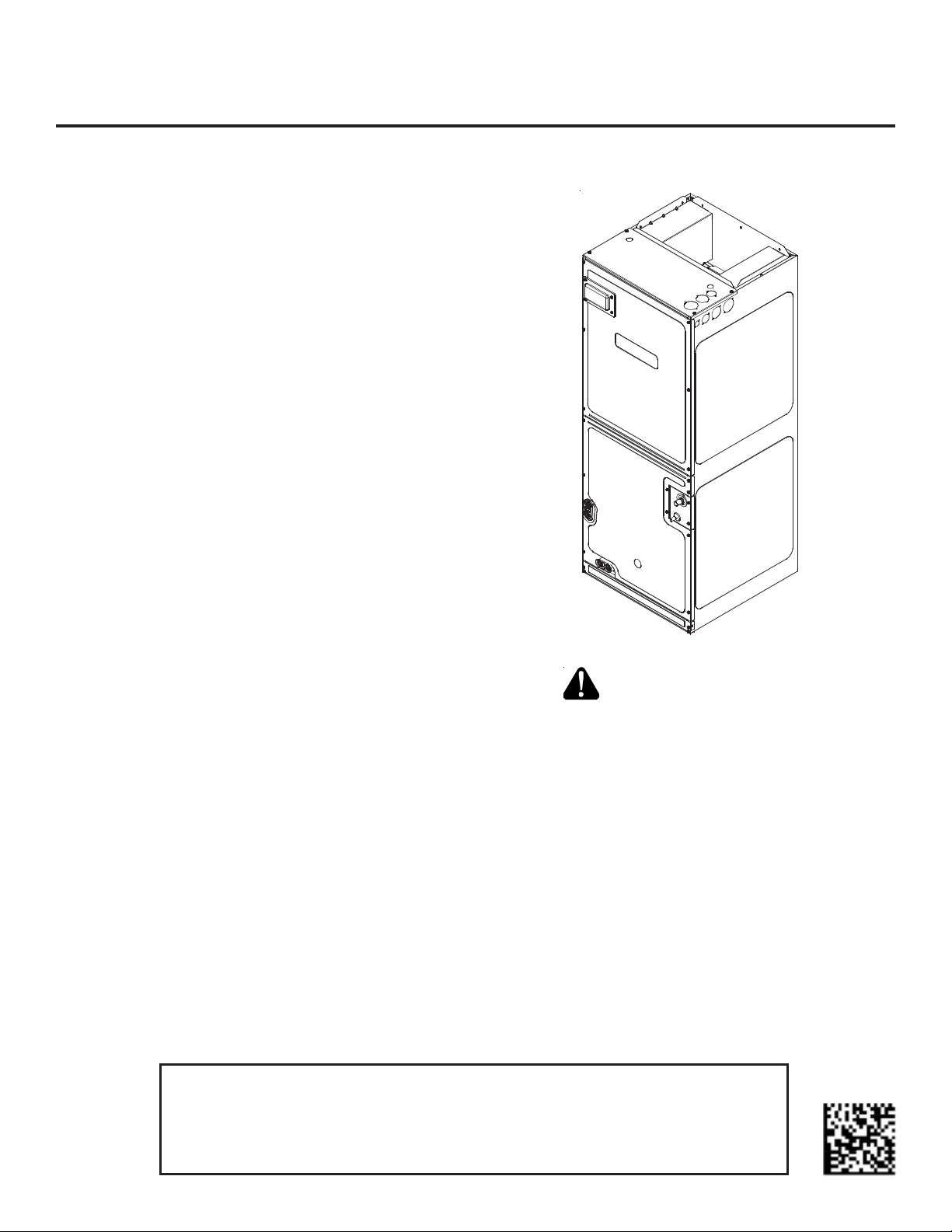
ARUF**14** / ASPT**14**
AIR HANDLERS INSTALLATION & OPERATING INSTRUCTIONS
Contents
1 Important Safety Instructions ................................... 1
2 Shipping Inspection ............................................... 3
2.1 Parts ............................................................. 3
2.2 Handling ........................................................ 3
3 Codes & Regulations .............................................. 3
4 Replacement Parts ................................................ 3
5 Pre-Installation Considerations ................................ 3
5.1 Preparation.....................................................3
5.2 System Matches ................................................3
5.3 Interconnecting Tubing ....................................... 3
5.4 Clearances ...................................................... 3
5.5 Horizontal Applications ...................................... 3
6 Installation Location ............................................. 4
6.1 Upflow Installation ........................................... 4
6.2 Horizontal Left Installation ................................. 4
6.3 Horizontal Right Installation / Downflow Installation ..4
7 Refrigerant Lines .................................................. 6
7.1 Tubing Size ..................................................... 6
7.2 Tubing Preparation ............................................ 6
7.3 Special Instructions ........................................... 6
7.4 Tubing Connections for Flowrator Model ..................8
7.5 Tubing Connections for TXV Models ........................ 8
7.6 ASPT**14** Models with Non-Adjustable TXV ............. 8
7.7 Thermal Expansion Valve System Adjustment ............9
8 Condensate Drain Lines ......................................... 10
9 Ductwork ........................................................... 11
9.1 Return Ductwork ............................................ 11
10 Return Air Filters ............................................... 11
11 Electric Heat ..................................................... 11
12 Electrical and Control Wiring ................................ 12
12.1 Building Electrical Service Inspection .................. 12
12.2 Wire Sizing .................................................. 12
12.3 Maximum Overcurrent Protection (MOP) .............. 12
12.4 Electrical Connections – Supply Voltage ................ 12
12.4.1 Air Handler Only (Non-Heat Kit Models) ...... 14
12.4.2 Air Handler - Non-Circuit Breaker Heat Kits . 14
12.4.3 Air Handler With Circuit Breaker Heat Kit ... 14
12.5 Low Voltage Connections ................................. 14
12.5.1 Thermostats ....................................... 14
12.6 Speed Tap Adjustment .................................... 14
13 Achieving 1.4% Low Leakage Rate ......................... 14
14 Start-Up Procedure ............................................. 15
15 Regular Maintenance ........................................... 15
16 Airflow Data ..................................................... 16
17 Air Handler Low Voltage Connections ...................... 18
18 Wiring Diagrams ................................................. 19
1 Important Safety Instructions
The following symbols and labels are used throughout this
manual to indicate immediate or potential safety hazards.
It is the owner’s and installer’s responsibility to read and
comply with all safety information and instructions accompanying these symbols. Failure to heed safety information
increases the risk of personal injury, property damage, and/
or product damage.
RECOGNIZE THIS SYMBOL
AS A SAFETY PRECAUTION.
IO-901F
10/2017
Keep this literature in a safe place for future reference.
ATTENTION INSTALLING PERSONNEL
Prior to installation, thoroughly familiarize yourself with this Installation Manual.
Observe all safety warnings. During installation or repair, caution is to be observed.
It is your responsibility to install the product safely and to educate the customer on its safe use.
HIGH VOLTAGE!
Disconnect ALL power before servicing.
Multiple power sources may be present.
Failure to do so may cause property damage,
personal injury or death.
When installing or servicing this equipment, safety
clothing, including hand and eye protection, is
strongly recommended. If installing in an area that has
special safety requirements (hard hats, etc.), bserve
o
these requirements.
Only personnel that have been trained to install,
adjust, service or repair (hereinafter, “service”) the
equipment specified in this manual should service
the equipment. The manufacturer will not be
responsible for any injury or property damage arising
from improper service or service procedures. If you
service this unit, you assume responsibility for any
injury or property damage which may result. In
addition, in jurisdictions that require one or more
licenses to service the equipment specified in this
manual, only licensed personnel should service the
equipment. Improper installation, adjustment,
servicing or repair of the equipment specified in this
manual, or attempting to install, adjust, service or
repair the equipment specified in this manual without
proper training may result in product damage,
property damage, personal injury or death.
To prevent the risk of property damage, personal
injury, or death, do not store combustible materials or
use gasoline or other flammable liquids or vapors in
the vicinity of this unit.
Do not connect to or use any device that is not designcertified by the manufacturer for use with this unit.
Serious property damage, personal injury, reduced
unit performance and/or hazardous conditions may
result from the use of such non-approved devices.
To avoid property damage, personal injury or death
due to electrical shock, this unit MUST have an
uninterrupted, unbroken
electrical ground. The
electrical ground circuit may consist of an
appropriately sized electrical wire connecting the
ground lug in the unit control box to the building
electrical service panel.
Other methods of grounding are permitted if performed
in accordance with the National Electric Code
(NEC)/American National Standards Institute
(ANSI)/National Fire Protection Association (NFPA) 70
and local/state codes. In Canada, electrical grounding
is to be in accordance with the Canadian Electric Code
(CSA) C22.1.
This product is factory-shipped for use with
208/240/1/60 electrical power supply.
DO NOT
reconfigure this air handler to operate with any other
power supply.
Advertencia especial para la instalación de calentadores ó manejadoras
de aire en áreas cerradas com o estacionamient os ó cuartos de ser vicio.
Las emis ion es de monóxido de carbono pueden circular a través
del aparat o cuando se opera en cu alquier modo.
CO can cause serious illness including perm anent brain
damage or death.
B10259-216
El monóx ido de carbono pued e causar enferme dades severas
como daño cerebral p ermanente ó m uerte.
B10259-216
RISQUE D'EMPOISONNEMENT AU
Cette ventilation est nécessaire pour éviter le danger d'intoxication
au CO po uvant surveni r si un appare il produisant du monoxyde
de carbon e co ntinue de fonctionner au sei n de l a zone confi née.
Le monoxyde de
des
dommag es permanents au cerv eau et meme la mor t.
carbone peut causer des maladies graves telles que
MONOXYDE DE CARBONE
B10259-216
2

2 Shipping Inspection
Always transport the unit upright; laying the unit on its side
or top during transit may cause equipment damage. The
installer should inspect the product upon receipt for shipping damage and subsequent investigation is the responsibility of the carrier. The installer must verify the model
number, specifications, electrical characteristics, and accessories are correct prior to installation. The distributor
or manufacturer will not accept claims from dealers for
transportation damage or installation of incorrectly shipped
units.
2.1 Parts
Also inspect the unit to verify all required components
are present and intact. Report any missing components
immediately to the manufacturer or to the distributor.
Use only factory authorized replacement parts (see Section 5). Make sure to include the full product model
number and serial number when reporting and/or obtaining service parts.
2.2 Handling
Use caution when transporting/carrying the unit. Do not
move unit using shipping straps. Do not carry unit with
hooks or sharp objects. The preferred method of carrying the unit after arrival at the job site is to carry via
a two-wheel hand truck from the back or sides or via
hand by carrying at the cabinet corners.
3 Codes & Regulations
This product is designed and manufactured to comply with
applicable national codes. Installation in accordance with
such codes and/or prevailing local codes/regulations is the
responsibility of the installer. The manufacturer assumes
no responsibility for equipment installed in violation of any
codes or regulations.
The United States Environmental Protection Agency (EPA)
has issued various regulations regarding the introduction
and disposal of refrigerants. Failure to follow these regulations may harm the environment and can lead to the
imposition of substantial fines. Should you have any ques-
tions please contact the local office of the EPA and/or refer to EPA’s website www.epa.gov.
4 Replacement Parts
When reporting shortages or damages, or ordering repair
parts, give the complete product model and serial numbers
as stamped on the product. Replacement parts for this
product are available through your contractor or local distributor. For the location of your nearest distributor consult the white business pages, the yellow page section of
the local telephone book or contact:
HOMEOWNER SUPPORT
GOODMAN MANUFACTURING COMPANY, L.P.
19001 KERMIER ROAD
WALLER, TEXAS 77484
(877) 254-4729
5 Pre-Installation Considerations
5.1 Preparation
Keep this document with the unit. Carefully read all
instructions for the installation prior to installing product. Make sure each step or procedure is understood
and any special considerations are taken into account
before starting installation. Assemble all tools, hardware and supplies needed to complete the installation.
Some items may need to be purchased locally. Make
sure everything needed to install the product is on hand
before starting.
5.2 System Matches
The entire system (combination of indoor and outdoor
sections) must be manufacturer approved and Air-Conditioning, Heating, and Refrigeration Institute (AHRI)
listed. NOTE: Installation of unmatched systems is not
permitted.
5.3 Interconnecting Tubing
Give special consideration to minimize the length of
refrigerant tubing when installing air handlers. Refer
to Remote Cooling/Heat Pump Service Manual
RS6200006, and TP-107 Long Line Set Application R410A for tubing guidelines. If possible, allow adequate
length of tubing such that the coil may be removed (for
inspection or cleaning services) from the cabinet without disconnecting the tubing.
5.4 Clearances
The unit clearance from a combustible surface may be
0". However, service clearance must take precedence.
A minimum of 24" in front of the unit for service clearance is required. Additional clearance on one side or
top will be required for electrical wiring connections.
Consult all appropriate regulatory codes prior to determining final clearances. When installing this unit in
an area that may become wet (such as crawl spaces),
elevate the unit with a sturdy, non-porous material. In
installations that may lead to physical damage (i.e. a
garage) it is advised to install a protective barrier to
prevent such damage. Always install units such that a
positive slope in condensate line (1/4" per foot) is allowed.
5.5 Horizontal Applications
If installed above a finished living space, a secondary
drain pan (as required by many building codes), must
be installed under the entire unit and its condensate
drain line must be routed to a location such that the
user will see the condensate discharge.
3
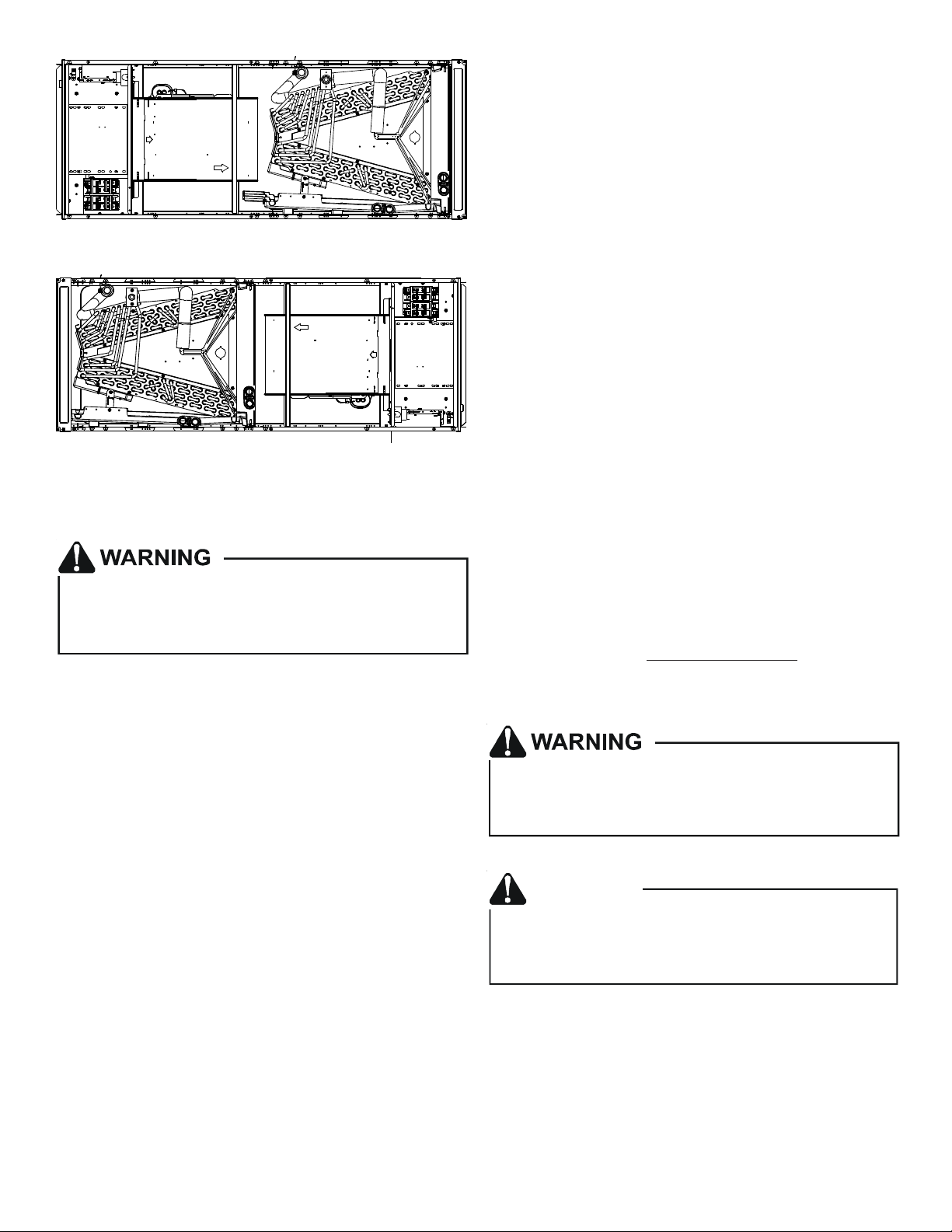
6 Installation Location
D
E
NOTE: These air handlers are designed for indoor installa-
tion only.
The ARUF**14** and ASPT**14** product lines may be installed
in one of the upflow, downflow, horizontal left or horizontal right orientations as shown in Figures 2, 3, 4 and 5. The
unit may be installed in upflow or horizontal left orientation as shipped (refer to specific sections for more information).
No field modifications are mandatory. However, to obtain
maximum efficiency, the horizontal drip shield, side drain
pan and drain pan extension can be removed.
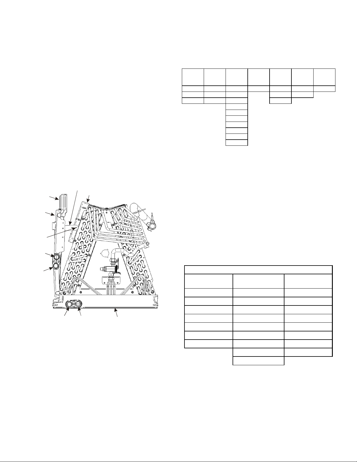
Side Drain Pan and Extension Removal: Refer to Figure 1,
remove the two (2) screws that secure the drip shield support brackets to the condensate collectors (front and back).
Unsnap the side drain pan from the bottom drain pan using
a screw driver or any small lever. The side drain pan, drip
shield brackets and the drain pan extension may now be
removed. From Figure 1, drain port labeled (A) is the primary drain for this application and condensate drain line
must be attached to this drain port. Drain port (a) is for the
secondary drain line (if used).
rip Pan
xten sion
Side
Drain
Pan
Screw
Drip Shield Bracket
Drip Shield
In applications where the air handler is installed in the horizontal left position, and the return air environment see
humidity levels above 65% relative humidity coupled with
total external static levels above 0.5” e.s.p., a condensate
kit is available for field application. Kit nomenclature can
be found in Table 1.
Kit
CMK0014
Condensate
Kit
CMK0008
Condensate
ARUF25B14 ARUF31B14 ARUF37C14 ARUF47D14 ARUF61D14 ASPT33C14 ASPT49C14
ARUF29B14 ASPT29B14 ARUF37D14 ASPT49D14 ASPT39C14
ASPT25B14 ASPT37B14 ARUF43C14 ASPT61D14
CMK0009
Condensate
Kit
CMK0010
Condensate
Kit
ARUF43D14
ARUF49C14
ARUF49D14
ASPT37C14
ASPT47C14
ASPT47D14
ASPT59C14
CMK0011
Condensate
Kit
CMK0012
Condensate
Kit
CMK0013
Condensate
Kit
CONDENSATE KIT
Table 1
6.3 Horizontal Right Installation / Downflow
Installation
When installing unit in the downflow position the appropriate (DFK) downflow kit is required to prevent “coil pan
sweating”. The DFK kit is not supplied with the air handler
and is available through your local distributor. See Table 2
for the correct DFK and follow the instructions provided for
installation.
Side drain pan extension must be removed in the downflow
and horizontal right applications for all models except:
ARUF47D14**, ARUF61D14**, ASPT61D14**, ASPT49D14**.
b
B
A
Pna
Main Drain Pan
SIDE DRAIN PAN REMOVAL
Figure 1
6.1 Upflow Installation
No field modifications are mandatory.
6.2 Horizontal Left Installation
No field modifications are permissible for this application.
Install unit as shown in Figure 4.
Remove red plugs from side drain pan before connecting
condensate drain pipes. Use removed plug to close drain
ports on vertical drain pan. The bottom right drain connection in side drain pan is the primary drain for this application and condensate drain line must be attached to this
drain connection. The bottom left drain connection in side
drain pan is for the secondary drain line (if used).
Refer to Figure 6 and 7 for the location of the components referenced in the following steps.
MODEL LIST FOR DOWNFLOW KIT
DFK-B
DOWNFLOW KIT
ARUF25B14** ARUF37C14** ARUF37D14**
ARUF29B14** ARUF43C14** ARUF43D14**
ARUF31B14** ARUF49C14** ARUF47D14**
ASPT25B14** ASPT33C14** ARUF49D14**
ASPT29B14** ASPT37C14** ARUF61D14**
ASPT35B14** ASPT39C14** ASPT61D14**
ASPT37B14** ASPT47C14** ASPT47D14**
1. Before inverting the air handler, remove blower access panel and coil access panel. The coil access panel
and tubing panel may remain screwed together during
this procedure. Remove and retain the seven (7) screws
securing the coil access panel to the cabinet and the
six (6) screws securing the blower access panel to the
cabinet.
DFK-C
DOWNFLOW KIT
DFK-D
DOWNFLOW KIT
ASPT49C14** ASPT49D14**
ASPT59C14**
DOWNFLOW KIT
Table 2
4
2. Slide the coil assembly out from the cabinet. Use the
drain pan to pull the assembly from the cabinet.
NOTE: DO NOT USE MANIFOLDS OR FLOWRATOR TO
PULL THE COIL ASSEMBLY OUT. FAILURE TO DO SO
MAY RESULT IN BRAZE JOINT DAMAGE AND LEAKS.
3. Removal of the center support is required on units with
21" wide cabinet. Remove and retain the two (2) screws
that secure the center support to the cabinet. Remove
the center support.
4. Position the unit in the downflow position.
5. Using the drain pan to hold the coil assembly, slide the
coil assembly back into the cabinet on the downflow
brackets as shown in Figure 8.
6. Reinstall the center support (if removed) using the two
(2) screws removed in Step 5.
7. Reinstall the coil access panels and reinstall blower
access panel removed in Step 1 as shown in Figure 9.
8. Drain Connections for Horizontal Right Installation
a. The bottom right drain connection in side drain pan
is the primary drain for this application and condensate drain line must be attached to this drain
connection. The bottom left drain connection is
for the secondary drain line (if used).
b. Remove red plugs from side drain pan before con-
necting condensate drain pipes. Use removed plug
to close drain ports on vertical drain pan.
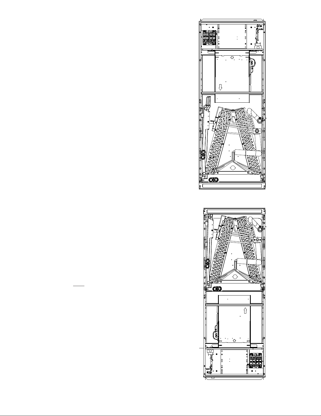
UPFLOW
Figure 2
9. Drain Connections for Downflow Installation
a. The bottom left drain connection in the vertical
drain pan is the primary drain for this application
and condensate drain line must be attached to this
drain connection. The bottom right drain connection is for the secondary drain line (if used).
b. Remove red plugs from vertical drain pan before
connecting condensate drain pipes.
NOTE: If removing only the coil access panel from the unit,
the filter access panel must be removed first. Failure
to do so will result in panel damage.
DOWNFLOW
Figure 3
5
HORIZONTAL LEFT
Figure 4
HORIZONTAL RIGHT
Figure 5
7 Refrigerant Lines
This product is factory-shipped with R410A and dry
nitrogen mixture gas under pressure. Use appropriate
service tools and follow these instructions to prevent
injury.
NOTE: Refrigerant tubing must be routed to allow adequate
access for servicing and maintenance of the unit.
7.1 Tubing Size
For the correct tubing size, follow the specification for
the condenser/heat pump.
7.2 Tubing Preparation
All cut ends are to be round, burr free, and clean. Failure to follow this practice increases the chances for
refrigerant leaks. The suction line is spun closed and
requires tubing cutters to remove the closed end.
NOTE: To prevent possible damage to the tubing joints,
do not handle coil assembly with manifold or flowrator
tubes. Always use clean gloves when handling coil assemblies.
7.3 Special Instructions
Units without a factory installed TXV come equipped
with a flowrator piston for refrigerant expansion. For
most installations with matching applications, no
change to the flowrator piston is required. However,
in mix-matched applications, a flowrator piston
change may be required. See the piston kit chart (provided in the literature packet) or consult your local
distributor for details regarding mix-matched
flowrator piston sizing. If the mix-match application
requires a different flowrator piston size, change the
flowrator piston in the flowrator body on the indoor
coil before installing the coil and use the procedure
in section 7.4.
NOTE: The use of a heat shield is strongly recommended
when brazing to avoid burning the serial plate or the
finish of the unit. Heat trap or wet rags must be used
to protect heat sensitive components such as service
valves and TXV valves sensing bulb.
Do not install the air handler in a location that violates the
instructions provided with the condenser. If the unit is
located in an unconditioned area with high ambient
temperature and/or high humidity, the air handler may be
subject to nuisance sweating of the air handler cabinet.
On these installations, a wrap of 2" fiberglass insulation
with a vapor barrier is recommended.
A quenching cloth is strongly recommended to prevent
scorching or marring of the equipment finish when
brazing close to the painted surfaces. Use brazing
alloy of 5% minimum silver content.
CAUTION
Applying too much heat to any tube can melt the tube. Torch
heat required to braze tubes of various sizes must be
proportional to the size of the tube. Service personnel must
use the appropriate heat level for the size of the tube being
brazed.
6
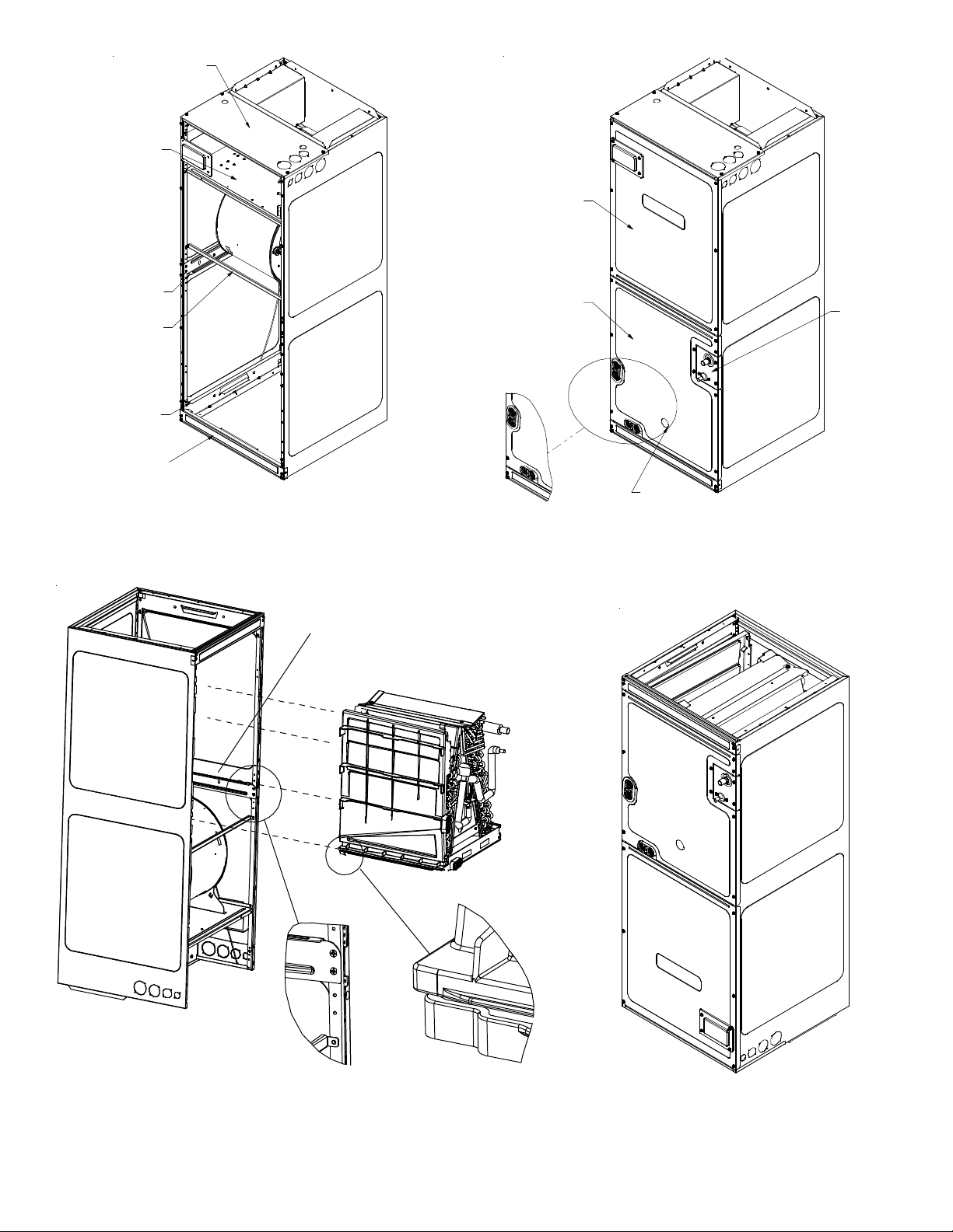
Upper Tie Plate
Control
Deck
Blower
Access
Panel
Downflow
Bracket
Center
Support
Filter
Bracket
Filter
Access
Panel
INTERNAL PART TERMINOLOGY
Figure 6
Coil slides
on the downflow bracket
Coil
Access
Panel
UV
Knockout
EXTERNAL PART TERMINOLOGY
Figure 7
Tub in g
Panel
IMPORTANT NOTE:
Ensure coil slides on the rails along the groove provided on the drain pan side
walls. Failure to do so will result in improper condensate drainage.
COIL INSTALLATION FOR DOWNFLOW
Figure 8
7
ACCESS PANEL CONFIGURATION FOR DOWNFLOW
OR HORIZONTAL RIGHT
Figure 9
7.4 Tubing Connections for Flowrator Model
1. Loosen the 13/16 nut 1 TURN ONLY to allow high pres-
sure tracer gas to escape. No gas indicates a possible
leak.
9. Torque the 13/16 nut to 7-25 ft-lbs. or tighten 1/6
turn.
2. After the gas has been expelled, remove the nut and
discard the black or brass cap plastic seal.
3. Remove the flowrator piston to verify it is the correct
size for the outdoor unit being installed and then replace the piston (changing size, if needed). See piston
kit chart in the literature kit for appropriate piston
size.
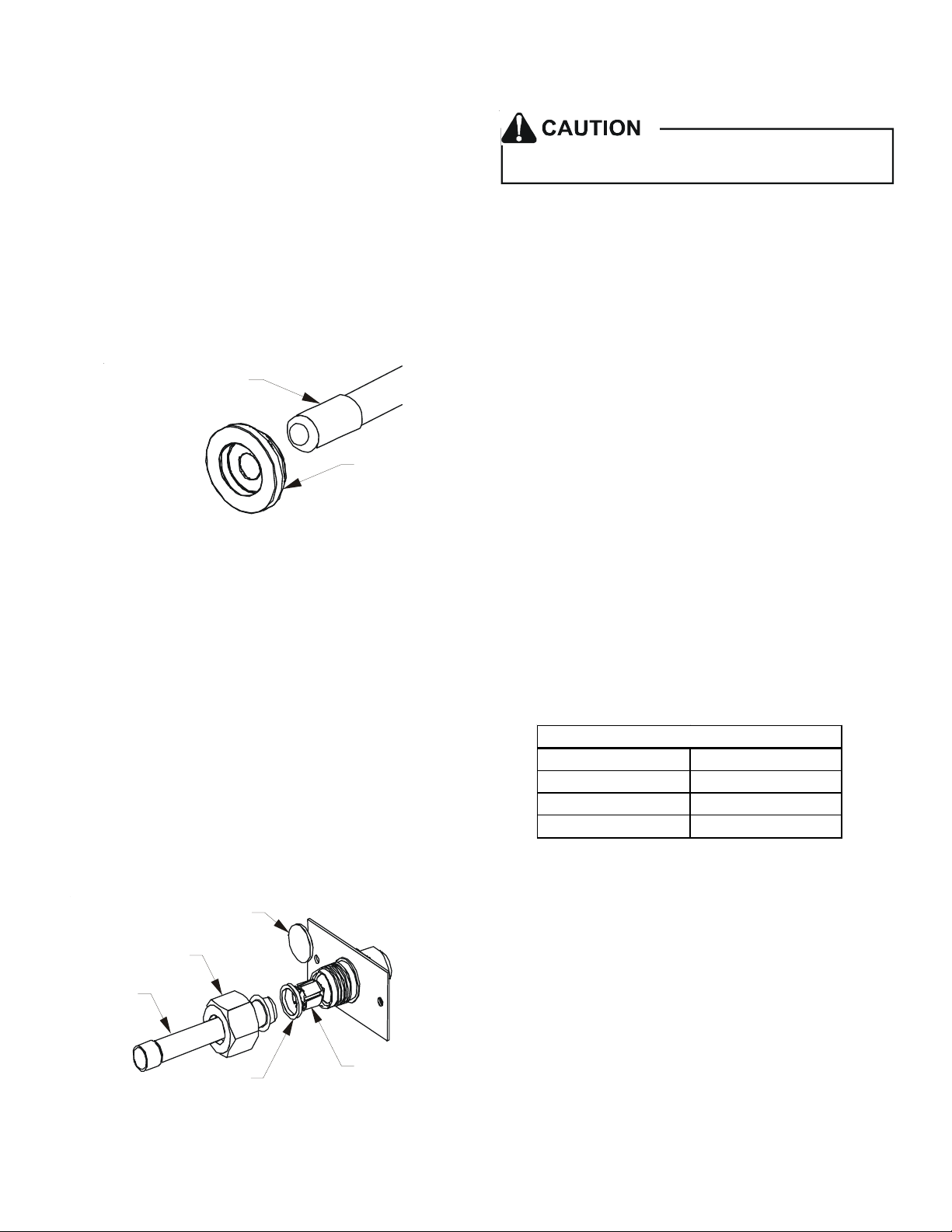
4. Remove the spin closure on the suction line using a
tube cutter and deburr the tube.
SUCTION LINE
WITH SPIN CLOSURE
RUBBER
GROMMET
SUCTION SPUN END AND GROMMET
Figure 10
5. Insert the suction line into the connection, slide the
insulation and the rubber grommet at least 18" away
from the braze joint.
6. Remove the tailpiece clamped to the exterior of the
cabinet or in the literature kit packet and slide the
13/16 nut into place.
Excessive torque can cause orifices to stick. Use the
proper torque settings when tightening orifices.
7.5 Tubing Connections for TXV Models
TXV models come with factory installed TXV with the
bulb pre-installed on the vapor tube.
1. Remove refrigerant tubing panel or coil (lower) access
panel.
2. Remove access valve fitting cap and depress the valve
stem in access fitting to release pressure. No pressure
indicates possible leak.
3. Replace the refrigerant tubing panel.
4. Remove the spin closure on both the liquid and suction
tubes using a tubing cutter.
5. Insert liquid line set into liquid tube expansion and
slide grommet about 18" away from braze joint.
6. Insert suction line set into suction tube expansion and
slide insulation and grommet about 18" away from braze
joint.
7. Braze joints. Quench all brazed joints with water or a
wet rag upon completion of brazing.
7.6 ASPT**14** Models with Non-Adjustable TXV
ASPT air handlers equipped with Parker non-adjustable TXV
should be charged by subcooling only.
7. Braze tailpiece to the line set liquid tube and braze
suction line connection. Quench all brazed joints with
a damp rag upon completion of brazing. Do not allow
water to enter the inside of the tubing.
8. AFTER THE TAILPIECE HAS COOLED, confirm position
of the white Teflon® seal and hand tighten the 13/16
nut.
PLASTIC or BRASS CAP
13/16” NUT
TAILPI ECE
WHITE
TEFLON SEAL
TAILPIECE JOINT
Figure 11
PISTON
Models
ASPT25B14** ASPT47D14**
ASPT29B14** ASPT47C14**
ASPT37B14** ASPT49D14**
ASPT37C14** ASPT59C14**
Table 3
See section 7.7 for detailed information on adjusting the
thermal expansion valve.
8
7.7 Thermal Expansion Valve System Adjustment
Run the system at Cooling for 10 minutes until refrigerant
pressures stabilize. Use the following guidelines and methods to check unit operation and ensure that the refrigerant
charge is within limits. Charge the unit on low stage.
1. Purge gauge lines. Connect service gauge manifold to
base-valve service ports.
2. Temporarily install a thermometer on the liquid line
at the liquid line service valve and 4-6" from the compressor on the suction line. Ensure the thermometer
makes adequate contact and is insulated for best possible readings. Use liquid line temperature to determine subcooling and vapor temperature to determine
superheat.
3. Check subcooling and superheat. Systems with TXV application should have a subcooling of 7 to 9ºF and superheat of 7 to 9 ºF.
a. If subcooling and superheat are low, adjust TXV to
7 to 9 ºF superheat, then check subcooling.
NOTE: To adjust superheat, turn the valve stem clockwise
to increase and counter clockwise to decrease.
b. If subcooling is low and superheat is high, add charge
to raise subcooling to 7 to 9ºF then check superheat.
c. If subcooling and superheat are high, adjust TXV
valve to 7 to 9 ºF superheat, then check subcooling.
d. If subcooling is high and superheat is low, adjust
TXV valve to 7 to 9 ºF superheat and remove charge to
lower the subcooling to 7 to 9ºF.
NOTE: Do NOT adjust the charge based on suction pressure
unless there is a gross undercharge.
4. Disconnect manifold set, installation is complete.
NOTE: Check the Schrader ports for leaks and tighten valve
cores if necessary. Install caps finger-tight.
SUBCOOL FORMULA =
SAT. LIQUID LINE TEMP. - LIQUID LINE TEMP.
SUPERHEAT FORMULA =
SUCT. LINE TEMP. - SAT. SUCT. TEMP.
NOTE: Expansion valve system in ASPT models are already
tuned for 16 SEER single stage Heat Pump, adjustment of
Expansion valve system is required in case subcool, superheat
does not match to Section 7.6.3 above or when these models
are installed with any other outdoor models.
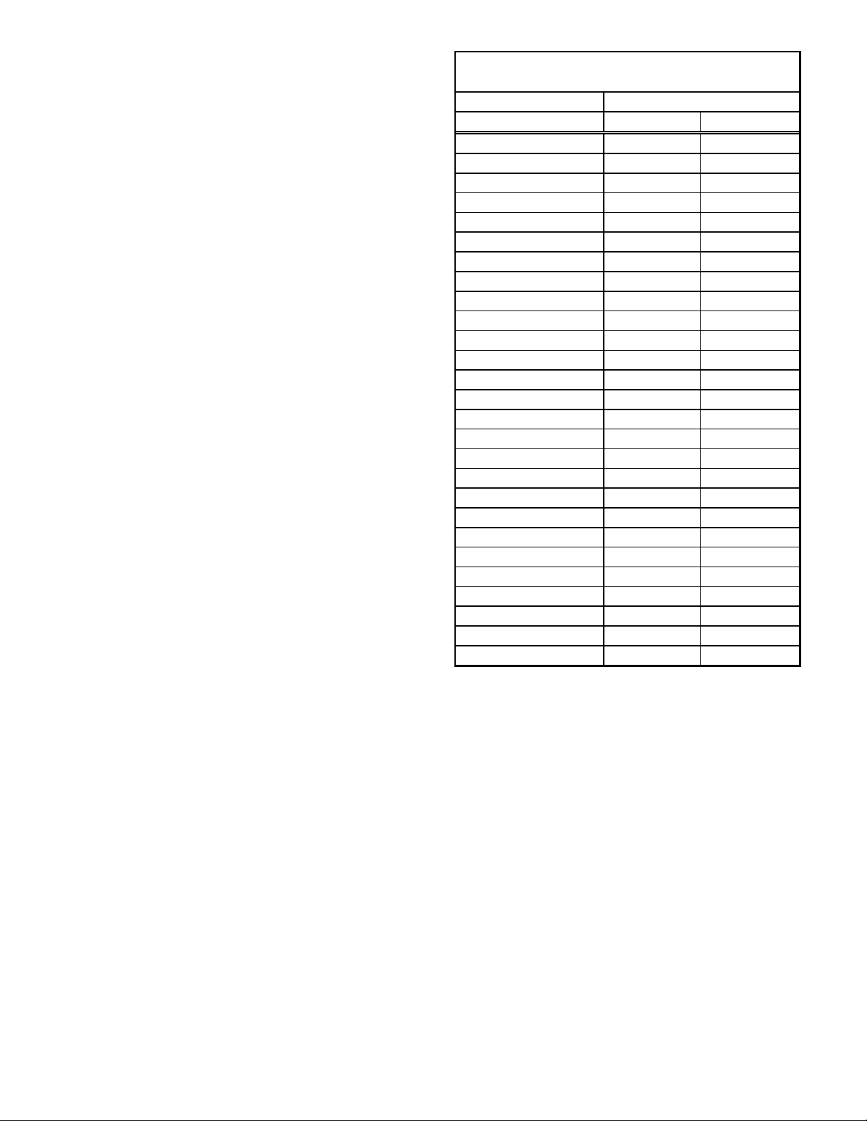
SATURATED SUCTION PRESSURE
TEMPERATURE CHART
SUCTION PRESSURE
PSIG R-22 R-410A
50 26 1
52 28 3
54 29 4
56 31 6
58 32 7
60 34 8
62 35 10
64 37 11
66 38 13
68 40 14
70 41 15
72 42 16
74 44 17
76 45 19
78 46 20
80 48 21
85 50 24
90 53 26
95 56 29
100 59 31
110 64 36
120 69 41
130 73 45
140 78 49
150 83 53
160 86 56
170 90 60
SATURATED SUCTION
9
 Loading...