


Goldstar LWN2432BAG, LWN2432BCG, Y5USC24-6A, LWC243NSAB0, Y5USC18-6A Service Manual
...website http://biz.LGservice.com
e-mail http://www.LGEservice.com/techsup.html
ROOM AIR CONDITIONER
SERVICE MANUAL
CAUTION
-BEFORE SERVICING THE UNIT,
READ THE SAFETY PRECAUTIONS IN THIS MANUAL.
-ONLY FOR AUTHORIZED SERVICE
MODELS: R1402/R1802/R1801H/M1802/R2102/R2402 R1803/R1804/R1803H/M1803R/R2103/R2403 LWM1836BCG/LWM1836BAG/LWM1836BAS/LWC243NSAB0 Y5USC18-6A/Y5USC24-6A/LWN2432BCG/LWN2432BAG
CONTENTS
1. PREFACE |
|
1.1 SAFETY PRECAUTIONS ............................... |
2 |
1.2 INSULATION RESISTANCE TEST................. |
2 |
1.3 SPECIFICATIONS .......................................... |
3 |
1.4 FEATURES ..................................................... |
7 |
1.5 CONTROL LOCATIONS ................................. |
7 |
2. DISASSEMBLY INSTRUCTIONS |
|
2.1 MECHANICAL PARTS.................................. |
10 |
2.1.1 FRONT GRILLE ................................... |
10 |
2.1.2 CABINET.............................................. |
10 |
2.1.3 CONTROL BOX ................................... |
10 |
2.2 AIR HANDLING PARTS................................ |
11 |
2.2.1 COVER (AT THE TOP)........................ |
11 |
2.2.2 BLOWER.............................................. |
11 |
2.2.3 FAN ...................................................... |
12 |
2.2.4 SHROUD.............................................. |
12 |
2.3 ELECTRICAL PARTS ................................... |
12 |
2.3.1 MOTOR................................................ |
12 |
2.3.2 COMPRESSOR ................................... |
12 |
2.3.3 CAPACITOR ........................................ |
13 |
2.3.4 POWER CORD .................................... |
13 |
2.3.5 THERMOSTAT .................................... |
13 |
2.3.6 ROTARY SWITCH ............................... |
14 |
2.3.7 SYNCHRONOUS MOTOR .................. |
14 |
2.4 REFRIGERATION CYCLE............................ |
15 |
2.4.1 CONDENSER ...................................... |
15 |
2.4.2 EVAPORATOR .................................... |
15 |
2.4.3 CAPILLARY TUBE............................... |
15 |
3. INSTALLATION |
|
3.1 HOW TO INSTALL THE UNIT ...................... |
18 |
3.2 HOW TO USE THE REVERSIBLE INLET GRILLE ....... |
18 |
3.3 WINDOW REQUIREMENTS......................... |
19 |
3.4 INSTALLATION KITS CONTENTS ............... |
19 |
3.5 SUGGESTED TOOL REQUIREMENTS ....... |
20 |
3.6 CABINET INSTALLATION ............................ |
21 |
4. TROUBLESHOOTING GUIDE |
|
4.1 OUTSIDE DIMENSIONS............................... |
23 |
4.2 PIPING SYSTEM .......................................... |
23 |
4.3 TROUBLESHOOTING GUIDE...................... |
24 |
5. SCHEMATIC DIAGRAM |
|
5.1 CIRCUIT DIAGRAM ...................................... |
29 |
5.2 ELECTRONIC CONTROL DEVICE .............. |
34 |
5.3 COMPONENTS LOCATION(FOR MAIN P.C.B ASM)....... |
36 |
5.4 COMPONENTS LOCATION(FOR DISPLAY P.C.B ASM)....... |
37 |
6. EXPLODED VIEW.................................. |
38 |
7. REPLACEMENT PARTS LIST ....... |
40 |
1. PREFACE
This SERVICE MANUAL provides various service information, including the mechanical and electrical parts etc. This room air conditioner was manufactured and assembled under a strict quality control system. The refrigerant is charged at the factory. Be sure to read the safety precautions prior to servicing the unit.
1.1 SAFETY PRECAUTIONS |
1.2 INSULATION RESISTANCE TEST |
1.When servicing the unit, set the ROTARY SWITCH or POWER SWITCH to OFF and unplug the power cord.
2.Observe the original lead dress.
If a short circuit is found, replace all parts which have been overheated or damaged by the short circuit.
3.After servicing the unit, make an insulation resistance test to protect the customer from being exposed to shock hazards.
—2—
1.Unplug the power cord and connect a jumper between 2 pins (black and white).
2.The grounding conductor (green or green & yellow) is to be open.
3.Measure the resistance value with an ohm meter between the jumpered lead and each exposed metallic part on the equipment at all the positions (except OFF or O) of the ROTARY SWITCH.
4.The value should be over 1MΩ .
1.3 SPECIFICATIONS
1.3.1 FOR R1402/R1802/R2102/R2402
|
|
|
MODELS |
R1402 |
R1802 |
|
R2102 |
|
R2402 |
REMARK |
|
ITEMS |
|
|
|
|
|
||||||
|
|
|
|
|
|
|
|
|
|
||
|
|
|
|
|
|
|
|
|
|
|
|
POWER SUPPLY |
|
|
|
1Ø, 115V, 60Hz |
1Ø, 208/230V, 60Hz |
|
|
||||
|
|
|
|
|
|
|
|
|
|
|
|
COOLING CAPACITY |
(Btu/h) |
14,000 |
17,500/ 18,000 |
20,500/21,000 |
|
23,500/24,000 |
|
||||
|
|
|
|
|
|
|
|
|
|
|
|
INPUT |
|
(W) |
1,380 |
1,800/ 1,850 |
2,410/2,470 |
|
2,760/2,820 |
|
|||
|
|
|
|
|
|
|
|
|
|
||
RUNNING CURRENT |
(A) |
12.0 |
9.0/ 8.3 |
11.8/10.8 |
|
13.7/12.7 |
|
||||
|
|
|
|
|
|
|
|
|
|
||
REFRIGERANT (R-22) CHARGE(g) |
680(24.0 OZ) |
800(28.2 OZ) |
|
730(25.8 OZ) |
|
890(31.4 OZ) |
|
||||
|
|
|
|
|
|
|
|
|
|
|
|
OPERATING |
INDOOR (°C) |
|
26.7(DB) 19.4(WB) |
|
|
||||||
TEMPERATURE |
|
|
|
|
|
|
|
|
|
|
|
OUTDOOR (°C) |
|
35(DB) 23.9(WB) |
|
|
|||||||
|
|
|
|
|
|||||||
|
|
|
|
|
|
|
|
|
|
||
EVAPORATOR |
|
|
|
3 ROW 15 STACKS |
|
4 ROW 18 STACKS |
|
||||
|
|
|
|
|
|
|
|
|
|
||
CONDENSER |
|
|
|
2 ROW 19 STACKS, L-BENDED TYPE |
|
2 ROW 19 STACKS, U-TYPE |
|
||||
|
|
|
|
|
|
|
|
|
|
|
|
FAN, INDOOR |
|
|
|
|
BLOWER |
|
|
||||
|
|
|
|
|
|
|
|
||||
FAN, OUTDOOR |
|
|
|
PROPELLER TYPE FAN WITH SLINGER-RING |
|
||||||
|
|
|
|
|
|
|
|
||||
FAN SPEEDS, FAN/COOLING |
|
2/3 |
|
|
|
||||||
|
|
|
|
|
|
|
|
|
|||
FAN MOTOR |
|
|
|
|
6 POLES |
|
|
||||
|
|
|
|
|
|
|
|||||
OPERATION CONTROL |
|
ROTARY SWITCH |
|
|
|||||||
|
|
|
|
|
|
|
|||||
ROOM TEMP. CONTROL |
|
THERMOSTAT |
|
|
|||||||
|
|
|
|
|
|
|
|
||||
AIR DIRECTION CONTROL |
VERTICAL LOUVER(RIGHT & LEFT) |
|
|||||||||
|
|
|
|
|
|
|
|||||
HORIZONTAL LOUVER(UP & DOWN) |
|
||||||||||
|
|
|
|
|
|
||||||
|
|
|
|
|
|
|
|
||||
CONSTRUCTION |
|
|
|
|
SLIDE IN-OUT CHASSIS |
|
|||||
|
|
|
|
|
|
|
|||||
PROTECTOR |
|
COMPRESSOR |
EXTERNALOVERLOADPROTECTOR |
INTERNAL OVERLOAD PROTECTOR |
|
||||||
|
|
|
|
|
|
|
|
|
|
|
|
|
FAN MOTOR |
INTERNAL THERMAL PROTECTOR |
|
||||||||
|
|
|
|||||||||
|
|
|
|
|
|
|
|
|
|||
POWER CORD |
|
|
|
1.8m(3WIRE WITH GROUNDING) |
1.6m (3 WIRE WITH GROUNDING) |
|
1.3m (3 WIRE WITH GROUNDING) |
|
|||
|
|
|
|
|
|
|
|
|
|
||
|
|
|
ATTACHMENT PLUG(CORD-CONNECTED TYPE) |
|
|||||||
|
|
|
|
|
|
||||||
|
|
|
|
|
|
|
|||||
DRAIN SYSTEM |
|
|
|
DRAIN PIPE OR SPLASHED BY FAN SLINGER |
|
||||||
|
|
|
|
|
|
|
|
|
|
|
|
NET WEIGHT |
|
(lbs/kg) |
117/53 |
120/54 |
|
143/65 |
|
146/66 |
|
||
|
|
|
|
|
|
|
|
|
|||
OUTSIDE DIMENSION |
|
(inch) |
26 x 1627/32 x 269/16 |
|
26 x 1627/32 x 305/16 |
|
|||||
(W x H x D) |
|
|
(mm) |
660 x 428 x 675 |
|
660 x 428 x 770 |
|
||||
|
|
|
|
|
|
|
|
|
|
|
|
NOTE: Please refer to Label Quality on the product since this specification may be changed for improving performance
—3—

1.3.2 FOR R1803/R1804/R2103/R2403/LWC243NSAB0
|
|
|
MODELS |
|
|
R1804 |
|
|
R2403/Y5USC24-6A |
|
|
|
|
|
R1803 |
|
LWM1836BAG/BAS/BCG |
|
R2103 |
LWN2432BCG/BAG |
REMARK |
||
ITEMS |
|
|
|
|
|
||||||
|
|
|
|
|
Y5USC18-6A |
|
|
LWC243NSAB0 |
|
||
|
|
|
|
|
|
|
|
|
|
|
|
POWER SUPPLY |
|
|
|
|
|
1Ø, 208/230V, 60Hz |
|
|
|||
|
|
|
|
|
|
|
|
|
|||
COOLING CAPACITY |
(Btu/h) |
17,500/ 18,000 |
|
20,500/21,000 |
23,500/24,000 |
|
|||||
|
|
|
|
|
|
|
|
|
|
||
INPUT |
|
(W) |
1,800/ 1,850 |
|
2,410/2,470 |
2,760/2,820 |
|
||||
|
|
|
|
|
|
|
|
|
|||
RUNNING CURRENT |
(A) |
9.0/ 8.3 |
|
11.8/10.8 |
13.7/12.7/12.9 |
|
|||||
|
|
|
|
|
|
|
|
|
|||
REFRIGERANT (R-22) CHARGE(g) |
750(26.5 OZ) |
|
710(25.0 OZ) |
980(34.6 OZ) |
|
||||||
|
|
|
|
|
|
|
|
|
|||
OPERATING |
INDOOR (°C) |
|
|
26.7(DB) 19.4(WB) |
|
|
|||||
|
|
|
|
|
|
|
|
|
|
||
TEMPERATURE |
|
|
|
|
|
|
|
|
|
|
|
OUTDOOR (°C) |
|
|
35(DB) 23.9(WB) |
|
|
||||||
|
|
|
|
|
|
||||||
|
|
|
|
|
|
|
|
||||
EVAPORATOR |
|
|
|
3 ROW 18 STACKS |
|
3 ROW 15 STACKS |
|
||||
|
|
|
|
|
|
|
|
|
|||
CONDENSER |
|
|
|
2 ROW 19 STACKS, L-BENDED TYPE |
2 ROW 19 STACKS, U-TYPE |
|
|||||
|
|
|
|
|
|
|
|
|
|
||
FAN, INDOOR |
|
|
|
|
|
BLOWER |
|
|
|||
|
|
|
|
|
|
|
|||||
FAN, OUTDOOR |
|
|
|
PROPELLER TYPE FAN WITH SLINGER-RING |
|
||||||
|
|
|
|
|
|
|
|
||||
FAN SPEEDS, FAN/COOLING |
|
2/3 |
|
|
|
||||||
|
|
|
|
|
|
|
|
|
|
||
FAN MOTOR |
|
|
|
|
|
6 POLES |
|
|
|||
|
|
|
|
|
|
|
|
|
|||
OPERATION CONTROL |
|
|
|
|
ROTARY SWITCH |
|
|
||||
|
|
|
|
|
|
|
|
|
|||
ROOM TEMP. CONTROL |
|
|
|
|
THERMOSTAT |
|
|
||||
|
|
|
|
|
|
|
|
||||
AIR DIRECTION CONTROL |
|
VERTICAL LOUVER(RIGHT & LEFT) |
|
||||||||
|
|
|
|
|
|
|
|||||
|
HORIZONTAL LOUVER(UP & DOWN) |
|
|||||||||
|
|
|
|
|
|
|
|||||
|
|
|
|
|
|
|
|
|
|
||
CONSTRUCTION |
|
|
|
|
|
SLIDE IN-OUT CHASSIS |
|
|
|||
|
|
|
|
|
|
|
|||||
PROTECTOR |
|
COMPRESSOR |
|
INTERNAL OVERLOAD PROTECTOR |
|
||||||
|
|
|
|
|
|
|
|
|
|
|
|
|
FAN MOTOR |
|
|
INTERNAL THERMAL PROTECTOR |
|
||||||
|
|
|
|
|
|||||||
|
|
|
|
|
|
|
|
||||
POWER CORD |
|
|
|
1.6m (3 WIRE WITH GROUNDING) |
1.3m (3 WIRE WITH GROUNDING) |
|
|||||
|
|
|
|
|
|
|
|
|
|
||
|
|
|
ATTACHMENT PLUG(CORD-CONNECTED TYPE) |
|
|||||||
|
|
|
|
|
|
||||||
|
|
|
|
|
|
||||||
DRAIN SYSTEM |
|
|
|
DRAIN PIPE OR SPLASHED BY FAN SLINGER |
|
||||||
|
|
|
|
|
|
|
|
|
|
||
NET WEIGHT |
|
|
(lbs/kg) |
120/54 |
|
143/65 |
146/66 |
|
|||
|
|
|
|
|
|
|
|
|
|||
OUTSIDE DIMENSION |
|
(inch) |
|
26 x 1627/32 x 269/16 |
|
26 x 1627/32 x 305/16 |
|
||||
|
|
|
|
|
|
|
|
|
|
||
(W x H x D) |
|
|
(mm) |
|
|
660 x 428 x 675 |
|
660 x 428 x 770 |
|
||
|
|
|
|
|
|
|
|
|
|
|
|
NOTE: Please refer to Label Quality on the product since this specification may be changed for improving performance
—4—
1.3.3 FOR R1801H
|
|
|
|
|
|
MODELS |
R1801H |
R1803H |
REMARK |
||
ITEMS |
|
|
|
|
|
||||||
|
|
|
|
|
|
|
|
||||
|
|
|
|
|
|
|
|
|
|
|
|
POWER SUPPLY |
|
|
1Ø, 208/ 230V, 60Hz |
|
|||||||
|
|
|
|
|
|
|
|
|
|
|
|
|
|
|
|
CAPACITY |
|
(Btu/h) |
17,500/ 18,000 |
|
|||
|
|
|
|
|
|
|
|
|
|
|
|
COOLING |
|
|
|
INPUT |
|
(W) |
1,940/ 2,000 |
1,800/1,850 |
|
||
|
|
|
|
|
|
|
|
|
|
||
|
|
RUNNING CURRENT (A) |
9.6/ 9.0 |
9.0/8.3 |
|
||||||
|
|
|
|
|
|||||||
|
|
|
|
|
|
|
|
|
|
|
|
|
|
|
|
E.E.R. |
(Btu/W.h) |
9.0 |
9.7 |
|
|||
|
|
|
|
|
|
|
|
|
|
|
|
|
|
|
|
CAPACITY |
|
(Btu/h) |
9,800/ 12,000 |
|
|||
|
|
|
|
|
|
|
|
|
|
||
HEATING |
INPUT |
|
(W) |
3,100/ 3,670 |
|
||||||
|
|
|
|
|
|
|
|
|
|
||
|
|
|
|
RUNNING CURRENT (A) |
15.0/ 16.0 |
|
|||||
|
|
|
|
|
|
|
|
|
|
|
|
OPERATING |
COOLING |
|
INDOOR (°C) |
26.7 (DB) |
19.4 (WB) |
|
|||||
|
|
|
|
|
|
||||||
OUTDOOR (°C) |
35 (DB) |
23.9 (WB) |
|
||||||||
TEMPERA- |
|
|
|
|
|
||||||
|
|
|
|
|
|
|
|
|
|
||
|
|
|
|
|
INDOOR (°C) |
21.1 (DB) |
15.6 (WB) |
|
|||
TURE |
HEATING |
|
|
|
|||||||
|
|
|
|
|
|
|
|||||
|
|
|
|
|
|
|
8.3 (DB) |
6.1 (WB) |
|
||
|
|
|
|
|
|
OUTDOOR (°C) |
|
||||
|
|
|
|
|
|
|
|
|
|
||
REFRIGERANT (R-22) CHARGE(g) |
740 (26.1 OZ) |
750(26.5 OZ) |
|
||||||||
|
|
|
|
|
|
|
|||||
EVAPORATOR |
|
|
3 ROW 15 STACKS |
3 ROW 18 STACKS |
LOUVERED- |
||||||
|
|
|
|
|
|
|
|
|
|
FIN TYPE |
|
CONDENSER |
|
|
2 ROW 19 STACKS, L-BENDED TYPE |
||||||||
|
|
|
|
|
|
||||||
FAN, INDOOR |
|
|
BLOWER |
|
|||||||
|
|
|
|
|
|
||||||
FAN, OUTDOOR |
|
|
PROPELLER TYPE FAN WITH SLINGER-RING |
|
|||||||
|
|
|
|
|
|||||||
FAN SPEEDS (FAN/COOLING/HEATING) |
1/ 2/ 2 |
|
|||||||||
|
|
|
|
|
|
|
|
|
|||
FAN MOTOR |
|
|
|
|
|
6 POLES |
|
||||
|
|
|
|
|
|
||||||
OPERATION CONTROL |
|
|
ROTARY SWITCH |
|
|||||||
|
|
|
|
|
|||||||
ROOM TEMP. CONTROL |
THERMOSTAT |
|
|||||||||
|
|
|
|
|
|
|
|
|
|
|
|
AIR DIRECTION CONTROL |
VERTICAL LOUVER (RIGHT & LEFT) |
|
|||||||||
|
|
|
|||||||||
HORIZONTAL LOUVER (UP & DOWN) |
|
||||||||||
|
|
|
|
|
|
|
|
|
|
||
|
|
|
|
|
|
||||||
CONSTRUCTION |
|
|
SLIDE IN-OUT CHASSIS |
|
|||||||
|
|
|
|
|
|
||||||
ELECTRIC HEATER |
|
|
3.5 KW, 230V |
|
|||||||
|
|
|
|
|
|
|
|
||||
|
|
|
|
COMPRESSOR |
INTERNAL OVERLOAD PROTECTOR |
|
|||||
|
|
|
|
|
|
||||||
PROTECTOR |
FAN MOTOR |
INTERANL THERMAL PROTECTOR |
|
||||||||
|
|
|
|
|
|
|
|
||||
|
|
|
|
ELECTRIC HEATER |
FUSE LINK, BIMETAL THERMOSTAT |
|
|||||
|
|
|
|
|
|
|
|
|
|
|
|
POWER CORD |
|
|
1.6m (3 WIRE WITH GROUDING) |
|
|||||||
|
|
|
|
|
|||||||
|
|
ATTACHMENT PLUG (CORD-CONNECTED TYPE) |
|
||||||||
|
|
|
|
|
|
|
|
|
|
||
|
|
|
|
|
|||||||
DRAIN SYSTEM |
|
|
DRAIN PIPE OR SPLASHED BY FAN SLINGER |
|
|||||||
|
|
|
|
|
|||||||
NET WEIGHT |
|
(lbs/kg) |
123/ 56 |
|
|||||||
|
|
|
|
|
|||||||
OUTSIDE DIMENSION |
|
(inch) |
26 x 1627/32 x 269/16 |
|
|||||||
(W x H x D) |
|
(mm) |
660 x 428 x 675 |
|
|||||||
|
|
|
|
|
|
|
|
|
|
|
|
NOTE: Please refer to Label Quality on the product since this specification may be changed for improving performance
—5—
ITEMS |
|
|
|
M1802 |
|
M1803R |
|
|
|
|
|
|
|
|
|
||
|
|
|
|
|
|
|
|
|
POWER SUPPLY |
|
|
|
1Ø, 208/230V, 60Hz |
|
|||
|
|
|
|
|
|
|
||
COOLING CAPACITY |
(Btu/h) |
17,500/ 18,000 |
|
|||||
|
|
|
|
|
|
|
|
|
INPUT |
|
(W) |
1,800/ 1,850 |
|
||||
|
|
|
|
|
|
|
|
|
RUNNING CURRENT |
(A) |
|
9.0/ 8.3 |
|
||||
|
|
|
|
|
|
|
||
REFRIGERANT (R-22) CHARGE(g) |
800(28.2 OZ) |
|
750(26.5 OZ) |
|
||||
|
|
|
|
|
|
|
||
OPERATING |
INDOOR (°C) |
26.7(DB) 19.4(WB) |
|
|||||
TEMPERATURE |
|
|
|
|
|
|
|
|
OUTDOOR (°C) |
35(DB) 23.9(WB) |
|
||||||
|
|
|
||||||
|
|
|
|
|
|
|
|
|
EVAPORATOR |
|
|
|
3 ROW 15 STACKS |
|
3 ROW 18 STACKS |
|
|
|
|
|
|
|
|
|
|
|
CONDENSER |
|
|
|
2 ROW 19 STACKS, L-BENDED TYPE |
|
|||
|
|
|
|
|
|
|
|
|
FAN, INDOOR |
|
|
|
|
BLOWER |
|
||
|
|
|
|
|
|
|
|
|
FAN, OUTDOOR |
|
|
|
PROPELLER TYPE FAN WITH SLINGER-RING |
|
|||
|
|
|
|
|
|
|
||
FAN SPEEDS, FAN/COOLING |
|
3/3 |
|
|||||
|
|
|
|
|
|
|
|
|
FAN MOTOR |
|
|
|
|
6 POLES |
|
||
|
|
|
|
|
|
|||
OPERATION CONTROL |
TOUCH PANEL |
|
||||||
|
|
|
|
|
|
|||
ROOM TEMP. CONTROL |
THERMISTOR |
|
||||||
|
|
|
|
|
|
|
|
|
AIR DIRECTION CONTROL |
VERTICAL LOUVER(RIGHT & LEFT) |
|
||||||
|
|
|
|
|||||
HORIZONTAL LOUVER(UP & DOWN) |
|
|||||||
|
|
|
|
|
|
|||
|
|
|
|
|
|
|
|
|
CONSTRUCTION |
|
|
|
SLIDE IN-OUT CHASSIS |
|
|||
|
|
|
|
|
|
|
||
PROTECTOR |
|
COMPRESSOR |
INTERNAL OVERLOAD PROTECTOR |
|
||||
|
|
|
|
|
|
|
|
|
|
FAN MOTOR |
INTERNAL THERMAL PROTECTOR |
|
|||||
|
|
|
||||||
|
|
|
|
|
|
|
|
|
POWER CORD |
|
|
|
1.6m (3 WIRE WITH GROUNDING) |
|
|||
|
|
|
|
|
|
|
||
|
|
|
ATTACHMENT PLUG(CORD-CONNECTED TYPE) |
|
||||
|
|
|
|
|
|
|||
|
|
|
|
|
|
|
||
DRAIN SYSTEM |
|
|
|
DRAIN PIPE OR SPLASHED BY FAN SLINGER |
|
|||
|
|
|
|
|
|
|
|
|
NET WEIGHT |
|
(lbs/kg) |
|
120/54 |
|
|||
|
|
|
|
|
|
|||
OUTSIDE DIMENSION |
|
(inch) |
26 x 1627/32 x 269/16 |
|
||||
(W x H x D) |
|
|
(mm) |
660 x 428 x 675 |
|
|||
|
|
|
|
|
|
|
|
|
NOTE: Please refer to Label Quality on the product since this specification may be changed for improving performance
—6—
1.4 FEATURES
•Designed for cooling only.
•Powerful and quiet cooling.
•Slide-in and slide-out chassis for the simple installation and service.
•Reversible inlet grille.
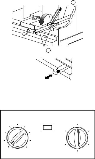
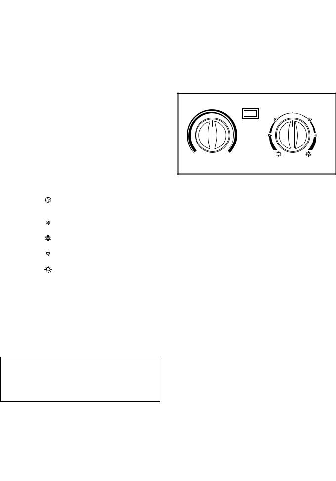
1.5 CONTROL LOCATIONS
1.5.1 COOLING ONLY MODEL
• VENTILATION
The ventilation lever must be in the CLOSE position in order to maintain the best cooling conditions.
When a fresh air is necessary in the room, set the ventilation lever to the OPEN position.
The damper is opened and room air is exhausted.
NOTE: Before using the ventilation feature, make the lever, as shown. First, pull down part  to horizontal line with part
  .
.
• THERMOSTAT
Thermostat will automatically control the temperature of the room. Select the higher number for the lower temperature of the room. The temperature is selected by positioning the knob to the desired position.
The 5 or 6 position is a normal setting for average conditions.
•Side air-intake, side cooled-air discharge.
•Built in adjustable THERMOSTAT.
•Washable one-touch filter.
•Compact size.
Part B
Part A
CLOSE  VENT
VENT  OPEN
OPEN
• OPERATION
OFF |
: Turns the air conditioner off. |
MED FAN |
: Permits the medium fan speed operation |
|
without cooling. |
LOW FAN |
: Permits the low fan speed operation |
|
without cooling. |
HIGH COOL: Permits cooling with the high fan speed operation.
MED COOL : Permits cooling with the medium fan speed operation.
LOW COOL: Permits cooling with the low fan speed
|
operation. |
• AUTO SWING |
|
ON |
: Air swing is operated while OPERATION knob |
|
is set to the COOL position. |
OFF |
:Stops the operation of air swing. |
Thermostat |
Auto Swing |
|
Operation |
|
5 |
6 |
|
Off |
|
4 |
|
Med |
High |
|
|
Off |
On |
||
|
Fan |
Cool |
||
|
|
|
||
3 |
7 |
|
|
|
2 |
8 |
|
|
|
1 |
9 |
|
Low |
Med |
|
Fan |
Cool |
||
Low Cool
—7—
1.5.2 COOLING AND HEATING MODEL
• CAUTION
When the air conditioner has been performing its cooling operation and is turned off or set to the fan position, wait at least 3 minutes before resetting to the cooling operation again.
• THERMOSTAT
Turn the thermostat control to the desired setting. The centrol position is a normal setting for average conditions. You can change this setting, if necessary, in accordance with your temperature preference.
The thermostat automatically controls cooling or heating, but the fan runs continuously whenever the air conditioner is in operation. If the room is too warm, turn the thermostat control clockwise. If the room is too cool, turn the themostat control anticlockwise.
• OPERATION
OFF |
( o ) |
:Turns the air conditioner off. |
|
FAN |
( |
) : Permits the low fan speed |
|
|
|
|
operation without cooling |
|
|
|
(heating). |
LOW COOL ( |
) : Permits cooling with the low fan |
||
|
|
|
speed operation. |
HIGH COOL( |
) : Permits cooling with the high fan |
||
|
|
|
speed operation. |
LOW HEAT ( |
) : Permits heating with the low fan |
||
|
|
|
speed operation. |
HIGH HEAT ( |
) : Permits heating with the high fan |
||
|
|
|
speed operation. |
• AUTO SWING |
|
||
ON |
: Starts the operation of air swing. |
||
OFF : Stops the operation of air swing.
•Before you turn the unit off, please press the Auto Swing switch to off.
A slight heat odor may come from the unit when first switching to HEAT after the cooling season is over. This odor, caused by fine dust particles on the heater, will disappear quickly.
Thermostat |
Operation |
||
|
|
Auto Swing |
Off |
|
|
|
|
|
Off |
On |
|
|
|
Fan |
Fan |
|
|
Low Heat |
Low Cool |
Warmer |
Cooler |
High Heat |
High Cool |
|
|
||
Wait Three Minutes
Before Restarting
— 8—
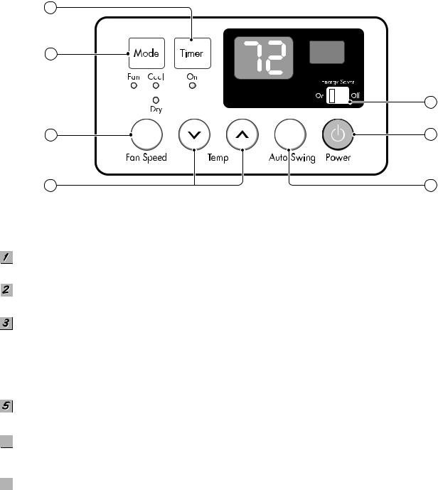
1.5.3 COOLING ONLY MODEL WITH TOUCH TYPE
3
2
6
4 |
1 |
5 |
7 |
Precaution: The Remote Control unit will not function properly if strong light strikes the sensor window of the air conditioner or if there are obstacles between the Remote Control unit and the air conditioner.
POWER BUTTON
Operation starts, when this button is pressed and stops when you press the button again.
OPERATION MODE SELECTION BUTTON
Select Cooling, or Fan or Dehumidification(Dry) mode with button. (Dry mode is not to all models.)
ON/OFF TIMER BUTTON
Set the time of starting and stopping operation. The timer is set by 1 hour.
 FAN SPEED SELECTOR
Select the fan speed in three steps.
- High [F3] Low[F1] Med[F2] High[F3]... .
ROOM TEMPERATURE SETTING BUTTON
Control the room temperature within a range of 60°F to 86°F by 1°F.
6ENERGY SAVER
The fan stops when the compressor stops cooling.
Approximately every 3 minutes the fan will turn on and check the room air to determine if cooling is needed.
7AUTO SWING BUTTON
Control the horizontal air direction by air swing system.
— 9—
2. DISASSEMBLY INSTRUCTIONS
— Before the following disassembly, POWER SWITCH is set to OFF and disconnected the power cord.
2.1 MECHANICAL PARTS
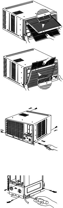
2.1.1 FRONT GRILLE
1. Open the inlet grille upward or downward.
2. Remove the screw which fastens the front grille.
3. Pull the front grille from the right side.
4. Remove the front grille. (See Fig. 1)
5. Re-install the component by referring to the removal procedure.
NOTE: Mark ∆ of inlet grille means opening direction.
Figure 1
2.1.2 CABINET
1.After disassembling the FRONT GRILLE, remove the screws which fasten the cabinet at both sides. Keep these for later use.
2.Remove the two screws which fasten the cabinet at back. (See Fig. 2)
3.Pull the base pan forward.
2.1.3 CONTROL BOX
1.Remove the front grille. (Refer to section 2.1.1)
2.Pull the base pan forward so that you can remove the 2 screws which fasten the cover control at the right side. (See Fig. 3)
3.Remove the 3 screws which fasten the control box. (See Fig. 3)
4.Discharge the capacitor by placing a 20,000 ohm resistor across the capacitor terminals.
5.Disconnect two wire housings in the control box.
6.Pull the control box forward completely.
7.Re-install the components by referring to the removal procedure. (See Fig. 3)
(Refer to the circuit diagram found on page 28~31 in this manual and on the control box.)
Figure 2
Figure 3
— 10—
2.2 AIR HANDLING PARTS
2.2.1 COVER (AT THE TOP)
1. Remove the front grille. (Refer to section 2.1.1)
2. Remove the cabinet. (Refer to section 2.1.2)
3. Remove 11 screws which fasten the brace and covers.
4. Remove the covers and the brace. (See Fig. 4) 5. Re-install the components by referring to the
removal procedure, above.
Figure 4
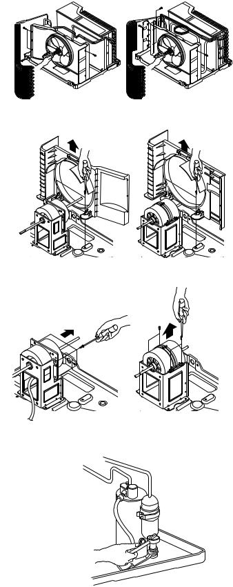
2.2.2 BLOWER
1.Remove the cover. (Refer to section 2.2.1)
2.Remove the 3 screws which fasten the evaporator at the left side and the top side. (See Fig. 4)
3.Move the evaporator sideward carefully.
4.Remove the 2 terminals carefully
(See Fig. 5, Electric Heater Model only)
5.Remove the 3 screws which fasten the Heater Cover.
(See Fig. 5, Electric Heater Model only)
6.Remove the Heater Cover.
(See Fig. 5, Electric Heater Model only)
7.Remove the orifice from the air guide carefully. (See Fig. 6, Except Electric Heater Model)
8.Remove the clamp which secures the blower with plier. (See Fig. 6)
9.Remove the blower with plier or your hand without touching blades. (See Fig. 7)
10.Re-install the components by referring to the removal procedure, above.
Figure 5
Figure 6
Figure 7
— 11—
2.2.3 FAN
1.Remove the cabinet. (Refer to section 2.1.2)
2.Remove the brace and shroud cover. (Refer to section 2.2.1)
3.Remove the side cover with 2 screws. (See Fig. 8(b))
4.Remove the 5 or 6 screws which fasten the condenser.
5.Move the condenser sideways carefully.
6.Remove the clamp which secures the fan.
7.Remove the fan. (See Fig. 8(a), 8(b))
8.Re-install the components by referring to the removal procedure, above.
2.2.4 SHROUD
1.Remove the fan. (Refer to section 2.2.3)
2.Remove the 2 screws which fasten the shroud.
3.Remove the shroud. (See Fig. 9(a), 9(b))
4.Re-install the component by referring to the removal procedure, above.
2.3 ELECTRICAL PARTS
2.3.1 MOTOR
1.Remove the cabinet. (Refer to section 2.1.2)
2.Remove the cover control and disconnect a wire housing in control box. (Refer to section 2.1.3)
3.Remove the blower. (Refer to section 2.2.2)
4.Remove the fan. (Refer to section 2.2.3)
5.Remove the 4 screws which fasten the motor. (See Fig. 10(a), 10(b))
6.Remove the motor.
7.Re-install the components by referring to the removal procedure, above.
2.3.2 COMPRESSOR
1.Remove the cabinet. (Refer to section 2.1.2)
2.Discharge the refrigerant system using FreonTM Recovery System.
If there is no valve to attach the recovery system, install one (such as a WATCO A-1) before venting the FreonTM . Leave the valve in place after servicing the system.
3.Disconnect the 3 leads from the compressor.
4.After purging the unit completely, unbraze the suction and discharge tubes at the compressor connections.
5.Remove the 3 nuts and the 3 washers which fasten the compressor. (See Fig. 11)
6.Remove the compressor.
7.Re-instill the components by referring to the removal procedure, above.
Figure 8(a) |
Figure 8(b) |
Figure 9(a) |
Figure 9(b) |
Figure 10(a) |
Figure 10(b) |
Figure 11
— 12—
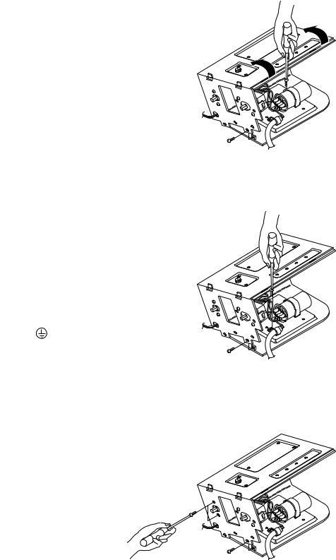
2.3.3 CAPACITOR
1.Remove the control box. (Refer to section 2.1.3)
2.Remove the screw and knobs which fasten the display panel.
3.Disconnect the 2 leads from the rocker switch and remove the panel.
4.Remove a screw and unfold the control box. (See Fig. 12)
5.Remove the screw and the clamp which fastens the capacitor. (See Fig. 12)
6.Disconnect all the leads of capacitor terminals.
7.Re-install the components by referring to the removal procedure, above.
Figure 12
2.3.4 POWER CORD
1.Remove the control box. (Refer to section 2.1.3)
2.Unfold the control box. (Refer to section 2.3.3)
3.Disconnect the grounding screw from the control box.
4.Disconnect 2 receptacles.
5.Remove a screw which fastens the clip cord.
6.Pull the power cord. (See Fig. 13)
7.Re-install the component by referring to the removal procedure, above.
(Use only one ground-marked hole |
for ground |
connection.) |
|
8.If the supply cord of this appliance is damaged, it must be replaced by the special cord.
(The special cord means the cord which has the
same specification marked on the supply cord |
Figure 13 |
|
|
fitted to the unit.) |
|
2.3.5 THERMOSTAT
1.Remove the control box. (Refer to section 2.1.3)
2.Unfold the control box. (Refer to section 2.3.3)
3.Remove the 2 screws which fasten the thermostat.
4.Disconnect all the leads of thermostat terminals.
5. Remove the thermostat. (See Fig. 14)
6. Re-install the components by referring to the removal procedure, above.
Figure 14
— 13—
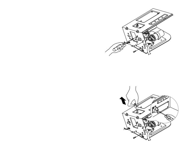
2.3.6 ROTARY SWITCH
1. Remove the control box. (Refer to section 2.1.3)
2. Unfold the control box. (Refer to section 2.3.3)
3. Remove 2 screws which fasten the rotary switch.
4. Disconnect all the leads of the rotary switch terminals.
5. Remove the rotary switch. (See Fig. 15)
6. Re-install the components by referring to the above removal procedure, above.
Figure 15
2.3.7 SYNCHRONOUS MOTOR
1. Remove the control box. (Refer to section 2.1.3)
2. Unfold the control box. (Refer to section 2.3.3)
3. Remove the crankshaft.
4. Disconnect all the leads of the synchronous motor.
5. Remove the 2 screws which fasten the synchronous motor. (See Fig. 16)
6. Re-install the components by referring to the removal procedure, above.
Figure 16
— 14—

2.4 REFRIGERATION CYCLE
CAUTION
Discharge the refrigerant system using FreonTM Recovery System.
If there is no valve to attach the recovery system, install one (such as a WATCO A-1) before venting the FreonTM. Leave the valve in place after servicing the system.
2.4.1 CONDENSER
1.Remove the cabinet. (Refer to section 2.1.2)
2.Remove the brace and the shroud cover. (Refer to section 2.2.1)
3.Remove 2 screws which fasten the side cover.(See Fig. 17(b))
4.Remove the 5 or 6 screws which fasten the condenser.
5.After discharging the refrigerant completely, unbraze the interconnecting tube at the condenser connections.
6.Remove the condenser.
7.Re-install the components by referring to notes. (See Fig. 17)
2.4.2 EVAPORATOR
1.Remove the cabinet. (Refer to section 2.1.2)
2.Remove the top cover and the brace. (Refer to section 2.2.1)
3.Discharge the refrigerant completely.
4.Remove the 3 screws which fasten the evaporator at the left side and the top side.
5.Move the evaporator sideward carefully and then unbraze the interconnecting tube at the evaporator connectors.
6.Remove the evaporator.
7.Re-install the components by referring to notes. (See Fig. 18)
2.4.3 CAPILLARY TUBE
1.Remove the cabinet. (Refer to section 2.1.2)
2.Remove the brace. (Refer to section 2.2.1)
3.After discharging the refrigerant completely, unbraze the interconnecting tube at the capillary tube.
4.Remove the capillary tube.
5.Re-install the components by referring to notes.
Figure 17(a)
Figure 17(b)
— 15—
 Loading...