


Dh400ey7
Lg Dh400ey7, Dh404ey7, Dh400my7, Ld40ey7, Ld40y7 Service Manual
...
http://biz.LGservice.com
Dehumidifier
SERVICE MANUAL
MODELS: DH300EY7/DH305Y7/DH300MY7/DH305T7
LD40Y7/DH400MY7
DH404EY7/DH400EY7/LD40EY7
DH504ELY7/LD50ELY7/LD50EBL/DH500MY7
LD65ELY7
CAUTION
- BEFORE SERVICING THE UNIT,
READ THE SAFETY PRECAUTIONS IN THIS MANUAL.
- ONLY FOR AUTHORIZED SERVICE.

—2—
1. PREFACE
1.1 SAFETY PRECAUTIONS...........................................................................................................................3
1.2 FEATURES AND DIMENSIONS ................................................................................................................3
1.2.1 FEATURES........................................................................................................................................3
1.2.2 DIMENSIONS ....................................................................................................................................3
1.3 MODEL NAMES .........................................................................................................................................4
1.4 SPECIFICATIONS......................................................................................................................................4
1.5 CONTROL TYPE........................................................................................................................................5
1.5.1 MECHANICAL TYPE.........................................................................................................................5
1.5.2 ELECTRONIC TYPE .........................................................................................................................5
1.6 HOW TO OPERATE DEHUMIDIFIER ........................................................................................................6
1.6.1 HOW DOES THE DEHUMIDIFIER WORK? .....................................................................................6
1.6.2 LOCATION FOR THE DEHUMIDIFIER.............................................................................................6
1.6.3 MICRO SWITCH................................................................................................................................6
1.6.4 AUTO DEFROST...............................................................................................................................6
1.6.5 HUMIDITY CONTROLLER................................................................................................................7
2. CIRCUIT DIAGRAM............................................................................................................................8
3.
DISASSEMBLY INSTRUCTIONS
3.1 MECHANICAL PARTS.............................................................................................................................15
3.1.1 BUCKET AND AIR FILTER.............................................................................................................15
3.1.2 FRONT CASE AND TOP COVER...................................................................................................15
3.1.3 CABINET AND CONTROL BOX.....................................................................................................15
3.2 CONTROL PARTS ..................................................................................................................................16
3.2.1 POWER CORD ASSEMBLY...........................................................................................................16
3.2.2 SENSOR ASSEMBLY.....................................................................................................................16
3.2.3 PWB(PCB) ASSEMBLY, MAIN.......................................................................................................16
3.2.4 CAPACITOR....................................................................................................................................16
3.2.5 MICRO SWITCH ASSEMBLY.........................................................................................................16
3.2.6 COIL ASSEMBLY, SOLENOID.......................................................................................................17
3.2.7 CONTROL PANEL..........................................................................................................................17
3.2.8 FAN AND MOTOR...........................................................................................................................18
3.2.9 DRAIN PAN.....................................................................................................................................18
3.3 REFRIGERATING CYCLE.......................................................................................................................19
3.3.1 CONDENSER, EVAPORATOR AND CAPILLARY TUBE...............................................................19
3.3.2 ROTARY COMPRESSOR ..............................................................................................................19
3.4 HOW TO REPLACE REFRIGERATION SYSTEM...................................................................................20
4. TROUBLESHOOTING GUIDE...................................................................................................22
5. EXPLODED VIEWS..........................................................................................................................24
6. REPLACEMENT PARTS LIST...................................................................................................32
CONTENTS
—3—
1. PREFACE
This Service Manual provides various service information, including the mechanical and electrical parts.
This dehumidifier was manufactured and assembled under the strict quality control procedures.
The refrigerant is charged at the factory. Be sure to read the safety precaution prior to servicing the unit.
1.1 SAFETY PRECAUTIONS
• Disconnect the power supply before servicing or replacing any component.
• Do not cut off the grounding prong or alter the plug in any manner.
1.2 FEATURES AND DIMENSIONS
1.2.1 FEATURES
• Quiet operation
• High efficiency
• Adjustable humidistat
• Automatic defrost
• Automatic shut-off
• Bucket-full indicator light
• Easy roll casters
• Removable & large capacity bucket.
• Washable air filter
• Two-speed fan
• Drain hose connection.
• Low temperature operation (DH504ELY7/LD50ELY7/LD50EBLY7/LD65ELY7)
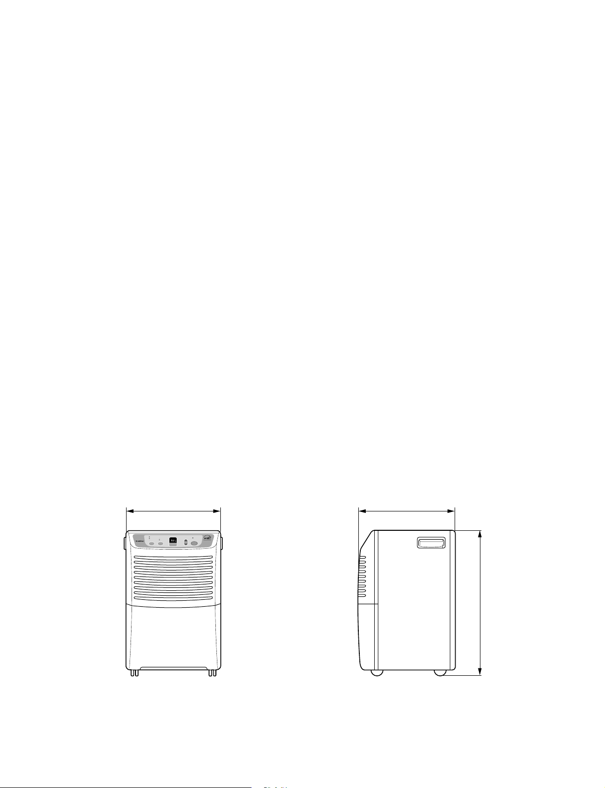
1.2.2 DIMENSIONS (mm/in)
Figure 1
385 (15
5
/
32
)
FAN
SPEED
TIMER
High
Low
Continuous On.
4Hr. On/Off
2Hr. On/Off
HUMIDITY
CONTROL
BUCKET
FULL
POWER
AUTO RESTART
HUMIDITY
SETTING
340 (13
3
/
8
)
540 (21
1
/
4
)
ENERGY STAR
1.3 MODEL NAMES
MODEL NAME
CAPACITY (Pints/24hrs) 30 40 50 65
DH305Y7, DH300MY7 DH400MY7,LD40Y7 DH500MY7 -
CONTROL
PANEL
MECHANICAL TYPE
ELECTRONIC TYPE
DH305T7
DH300EY7
DH404Y7 LD65ELY7
DH400EY7,LD40EY7
DH504EL
LD50EL
LD50EBLY7
Y7
Y7
1.4 SPECIFICATIONS
DH504ELY7
MODELS
ITEMS
POWER SUPPLY(Phase,V,Hz)
INPUT(W
RUNNING CURRENT(A
ENERGY FACTOR(L/kw.h
REFRIGERAN
REFRIGERANT CHARGE, oz(g
SOLENOID VALVE*
COMPRESSOR MODEL No. SD074SW QA075CDB QA114CBD
PROTECTOR
CAPACITO
MOTOR ASSEMBLY,SINGL
SWITCH ASSEMBLY,MICRO
OUTSIDED MENSIONS
WxHxD,mm(in)
NET WEIGHT,kg(lbs
) 560 560 8 0
)
) 1.05 1.50 1.75 1.60
T
) 4.94(140) 5.82 9.17(260) 8.64(245)
OPEN
THERMISTOR
R 40µF, 270VAC 35µF, 270VAC 35µF, 270VAC
CLOSE
E Shaded pole motor, 72W/1.4A, Thermal cutoff:266°F/130°C
)
DH305Y7
DH300MY7
DH300EY7
SD074SW
35µF, 270VAC
20.1
DH305T7
5.1
5.29(150)
-
QA064CBA
(
)
44.3
DH400MY7, LD40Y
DH404EY
DH400EY7, LD40EY
OVERLOAD PROTECTOR FOR COMPRESSOR
INTERNAL PROTECTOR(FUSE)FOR MOTOR
385X540X340(15 5/32 x 21 1/4 x 13 3/8)
7
255
5.0 7.6
(165)
33.8
-
(44.5
2
20.
7
LD50ELY7
DH500MY7
7
LD50EBLY7
1Ø, 115V,60Hz
4
5.
R22
°F(1±0.5°C)
°F(10±0.5°C)
50
Using Temp/Humid.:-4~122°F(-20~50°C)/95%RH
Rating:7W/90mA
15A/250VAC
) 22.5(49.6) 22.2(48.9)
LD65ELY
Shaded pole motor, 91W/1.8A,
Thermal cutoff:266
7
0
°F/130°C
*NOTE:Specifications are subject to minor change without notice for further improvement.
—4—
—5—
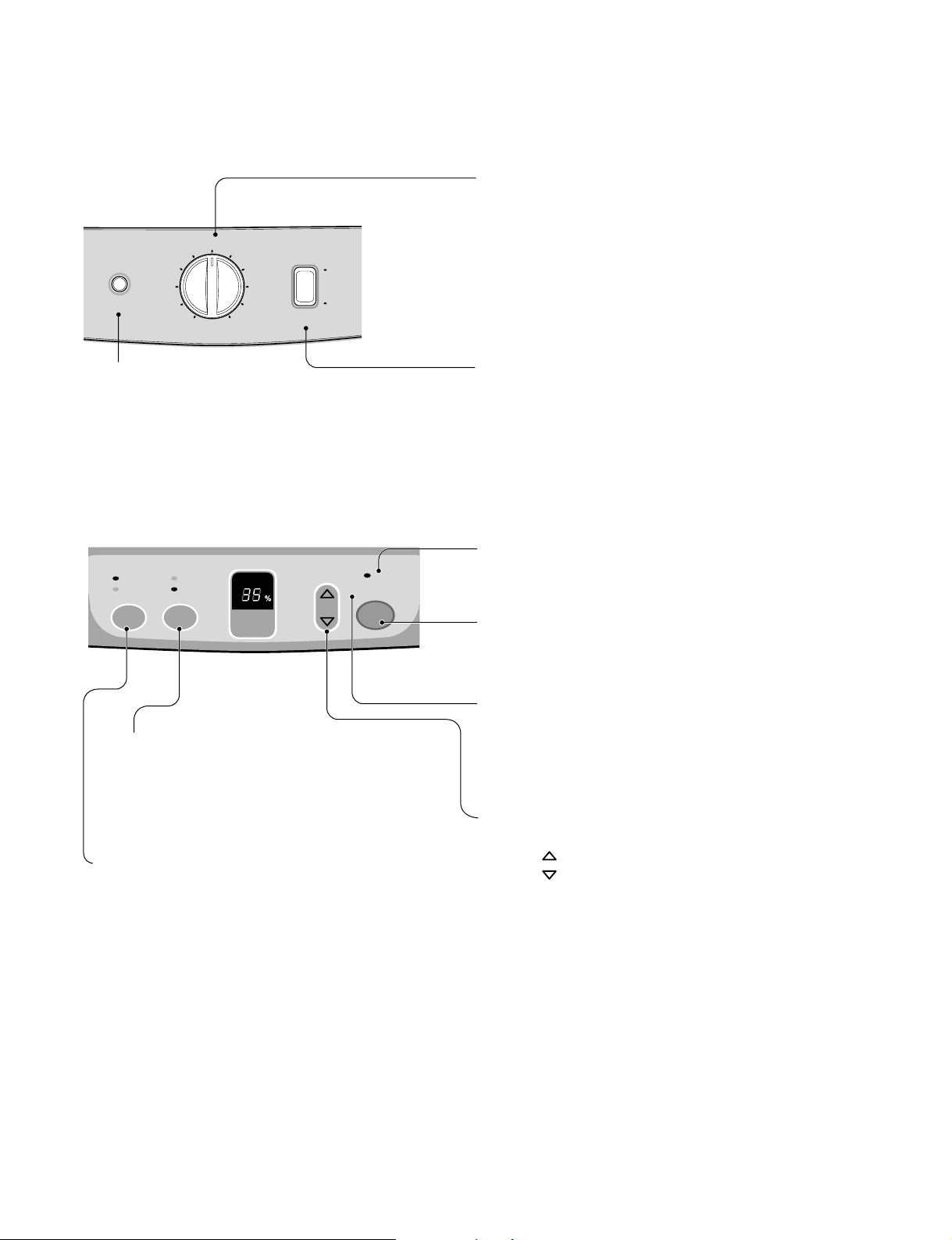
Humidity Control
• When you first use the dehumidifier, turn the humidity
control to 5 or 6. If you still have moisture, turn the
humidity control to a higher setting.
MAX is the highest setting.
• When excess moisture and dampness odors are
gone, adjust the control to a lower setting. Use the
dehumidifier as long as excess moisture is present.
Fan Speed
• The fan control adjusts the fan speed.
Set the fan control to HIGH for maximum moisture
removal. When the humidity has been reduced and
quiet operation is preferred, set the fan control to
LOW.
Bucket Full Indicator
• This light glows when the water bucket is full and needs
to be emptied.
Power
• Operation starts when this button is pressed and stops
when the button is pressed again.
Auto Shut-Off
• This light glows when the bucket is full, or when
the bucket is removed or not placed in the proper
position. In these cases the Water Level Control
Switch shuts off the dehumidifier.
• When the light glows, check the bucket condition.
Fan Speed
• This controls the speed of the airflow.
• High: Fan speed is set to high.
• Low: Fan speed is set to low.
• When Fan Speed button is pressed, the fan speed
mode is changed.
Timer
• Press this button to select type of operation.
• Select continuous On for uninterrupted operation.
• Select either 2 or 4 hr. On/Off for cycled operation:
The unit will operate for 2 or 4 hours, and then shut
off completely for 2 or 4 hours.
The cycle repeats until you change the setting.
• When Timer button is pressed, the Timer indicator
lights shift as follow from 2hr.On/Off to 4hr.On/Off.
Auto Restart
•
Once power is restored after a power outage, the unit
returns to its previous operation setting after a 2 minute
delay.
The fan runs immediately when the power is restored.
Figure 2
Figure 3
Humidity Control
• This button controls the humidity in the room.
• Press button to raise the humidity setting.
• Press button to lower the humidity setting.
• The humidity setting can be set to a permanent "On"
setting or to a specific humidity setting between 35% and
70% in 5% increments.
• "On" setting: Dehumidifier runs continuously regardless
of humidity condition.
• 35% - 70% setting: Dehumidifier runs on and off
according to surrounding humidity conditions.
1.5 CONTROL TYPE
1.5.1 Mechanical type
1.5.2 Electronic type
5
6
4
3
2
Auto
Shut-Off
1
Off
Humidity Control
Constantly On.
4hr. On/Off
2hr. On/Off
TIMER
FAN
SPEED
High
Low
7
9
Max
HUMIDITY
SETTING
8
Fan Speed
HUMIDITY
CONTROL
High
Low
BUCKET
FULL
AUTO RESTART
POWER
—6—
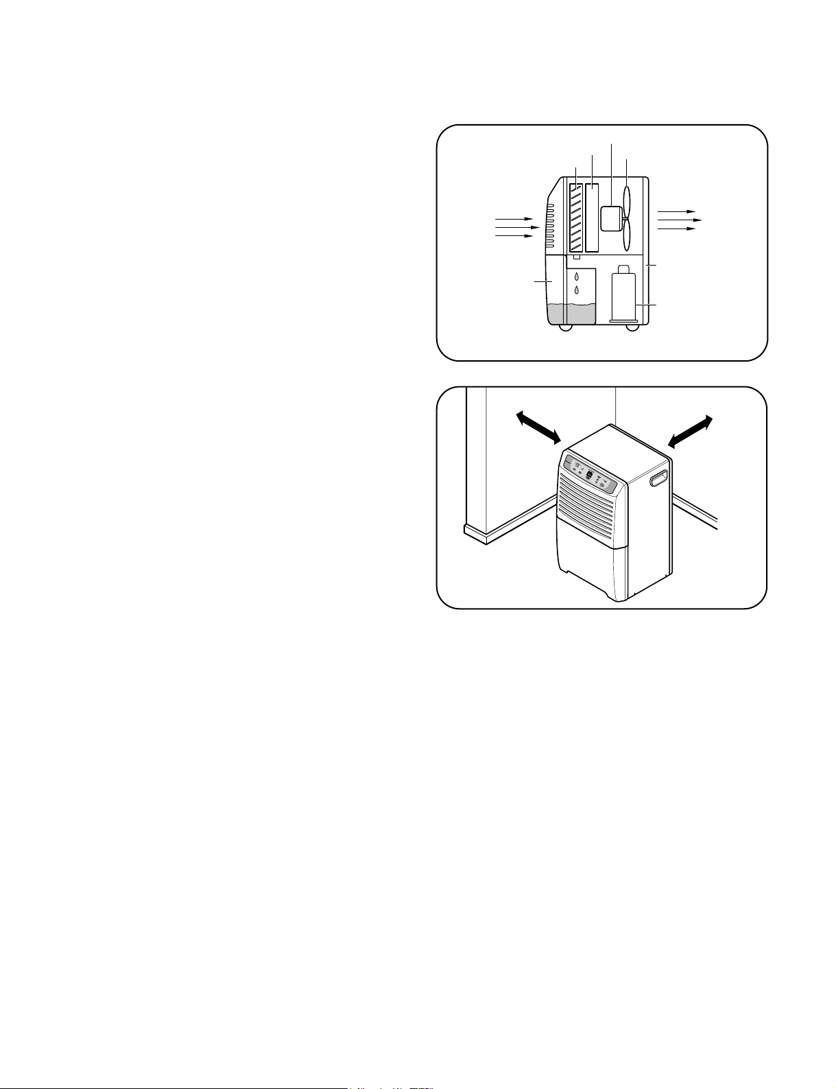
1.6.1 HOW DOES THE DEHUMIDIFIER WORK?
Moist, humid air is drawn over a cold refrigerated
dehumidifying coil. Moisture in the air condenses on this
coil and drains into a bucket (or through the bucket into a
hose and drain).
Dry, clean air is drawn over the condenser where it is
actually heated several degrees and discharged out the
rear grill into the room. (See Figure 4)
■ It is normal for the surrounding air to become
slightly warmer as the dehumidifier operates.
This warming effect further reduces the relative humidity
of the surrounding air.
1.6.2 LOCATION FOR THE DEHUMIDIFIER
Allow at least 12 inches of space on all sides of the
unit for good air circulation. (See Figure 5)
■ The dehumidifier must be operated in an enclosed
area to be most effective.
■ Close all doors, windows and other outside
openings to the room.
Place the dehumidifier in a location that does not
restrict air flow into the front grille or out the rear grille.
The operation of dehumidifier in a basement will have
little or no effect in drying an adjacent enclosed
storage area, such as a closet, unless there is
adequate circulation of air in and out of the area.
Fan
Side View
Condenser
Evaporator
Motor
Compressor
Rear Grille
Bucket
Dry
Air Out
Humid
Air In
12"
12"
Figure 4
Figure 5
1.6 HOW TO OPERATE DEHUMIDIFIER
1.6.3 MICRO SWITCH
The micro switch assembly, which is located on the drain pan of inside unit, automatically shuts off the dehumidifier when the
bucket is full (note, the Auto Shut Off lights, to indicate bucket must be emptied). The bucket replaces in its place, the unit again
turns itself on.
1.6.4 AUTO DEFROST
When frost builds up on the cooling coils, the unit will automatically cycle off until the frost disappears. The fan continues to run.
NOTE: The unit will not operate satisfactorily if the room temperature is below 65˚F(18˚C). If the dehumidifier is
operated in low temperature conditions frost can form in the evaporator coil and the unit will cycle ON/OFF
repeatedly. In this case, please check your room temperature conditions and stop the unit.
NOTE:
The low temperature operation feature in the DH504ELY7, DH50ELY7 and DH65ELY7 models will continuously
cycle up to a temperature of 42°F(6°C).
—7—
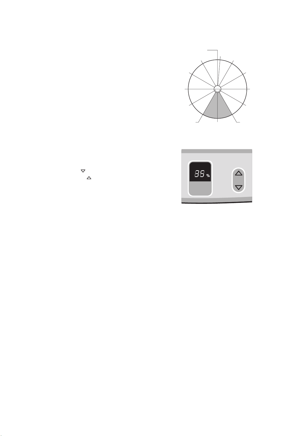
1.6.5 HUMIDITY CONTROLLER
1.6.5.1 Mechanical Type
The humidity control can be set anywhere between Off and
Max for normal operation.
If you need more dehumidification, turn the Humidity Control
toward Max. If you need less dehumidification, turn the
Humidity Control toward Off.
The relative humidity range is from 20% to 80%. (See
Figure 6)
Turn the Humidity Control to Off to stop the unit manually.
1.6.5.2 Electronic Type
The humidity control can be set 'on' or 35%-70%
RH(Relative Humidity) for normal operation. (See Figure 7)
If you need drier air, press the Humidity Control button.
If you need moister air, press the Humidity Control
button.
Press the Power button to stop the unit manually.
HUMIDITY
CONT
ROL
HUMIDITY
SETTING
42% R.H
40%
7(30%)
6(35%)4(50%)
3(60%)
2(70%)
1(80%)
5(42%)
8(25%)
9(20%)
Max.Off
DEAD DIAL
Figure 6
Figure 7
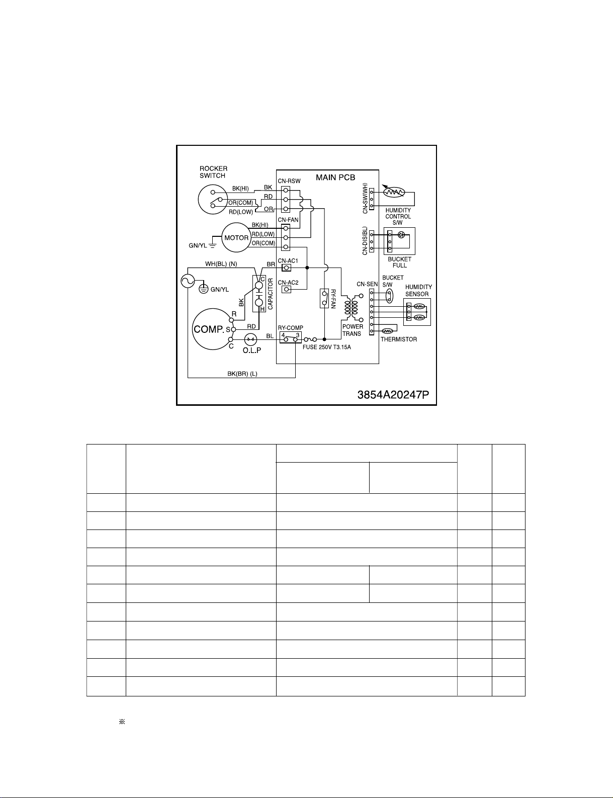
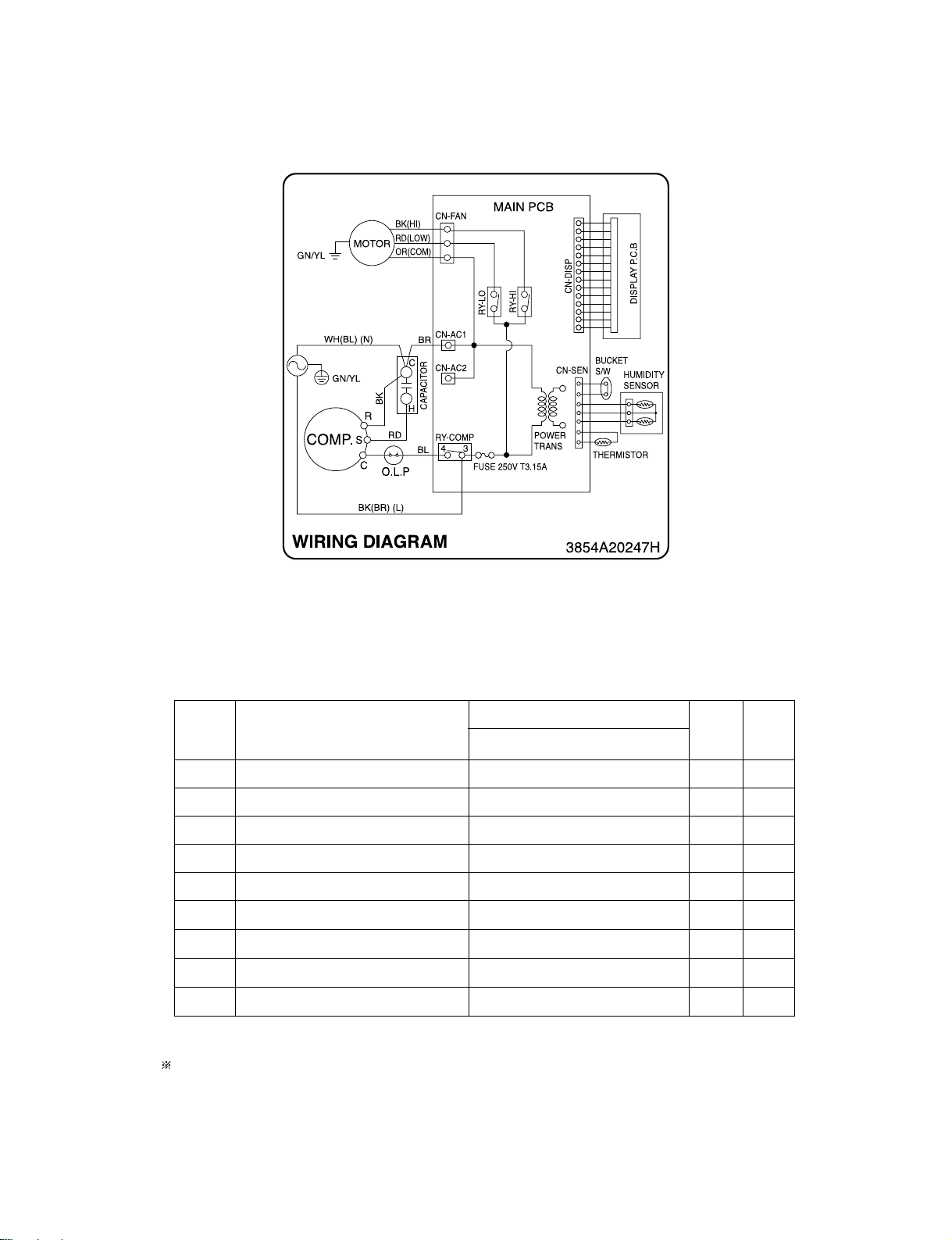
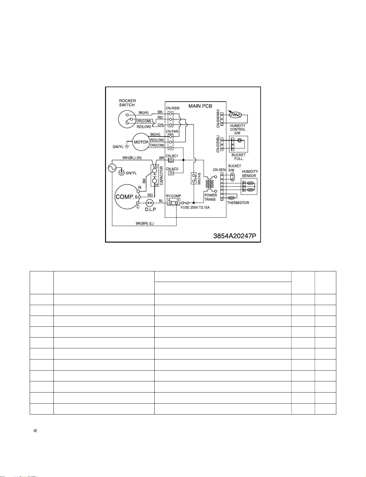
2. CIRCUIT DIAGRAM
• MODEL : DH305Y7, DH300MY7
NO.
POWER CORD ASSEMBLY
1
SWITCH, ROCKER
2
MOTOR ASSEMBLY
3
CAPACITOR
4
COMPRESSOR, SET
5
OLP
6
PWB(PCB) ASSEMBLY, DISPLAY
7
SENSOR ASSEMBLY
8
SWITCH ASSEMBLY, ROTARY
9
SWITCH ASSEMBLY, MICRO
10
PWB(PCB) ASSEMBLY, MAIN
11
S: SERVICE PARTS A: ALTERNATE PARTS N: NOT SERVICE PARTS
DESCRIPTION
DH305Y7
DH300MY7
TBZ30871801
EAF35787201
PART NO.
DH305T7
6411A20001Z
6600FX5001G
4681A20040Q
0CZZA20005J
TBZ31057901
6750U3L001A
6871A20289B
6877A30013L
6601A30006A
6600A30003C
6871A10142A
Q'TY
PER SET
MARKS
1
1
1
1
1
1
1
1
1
1
1
RE-
S
S
S
S
S
S
S
S
S
S
S
—8—
—9—
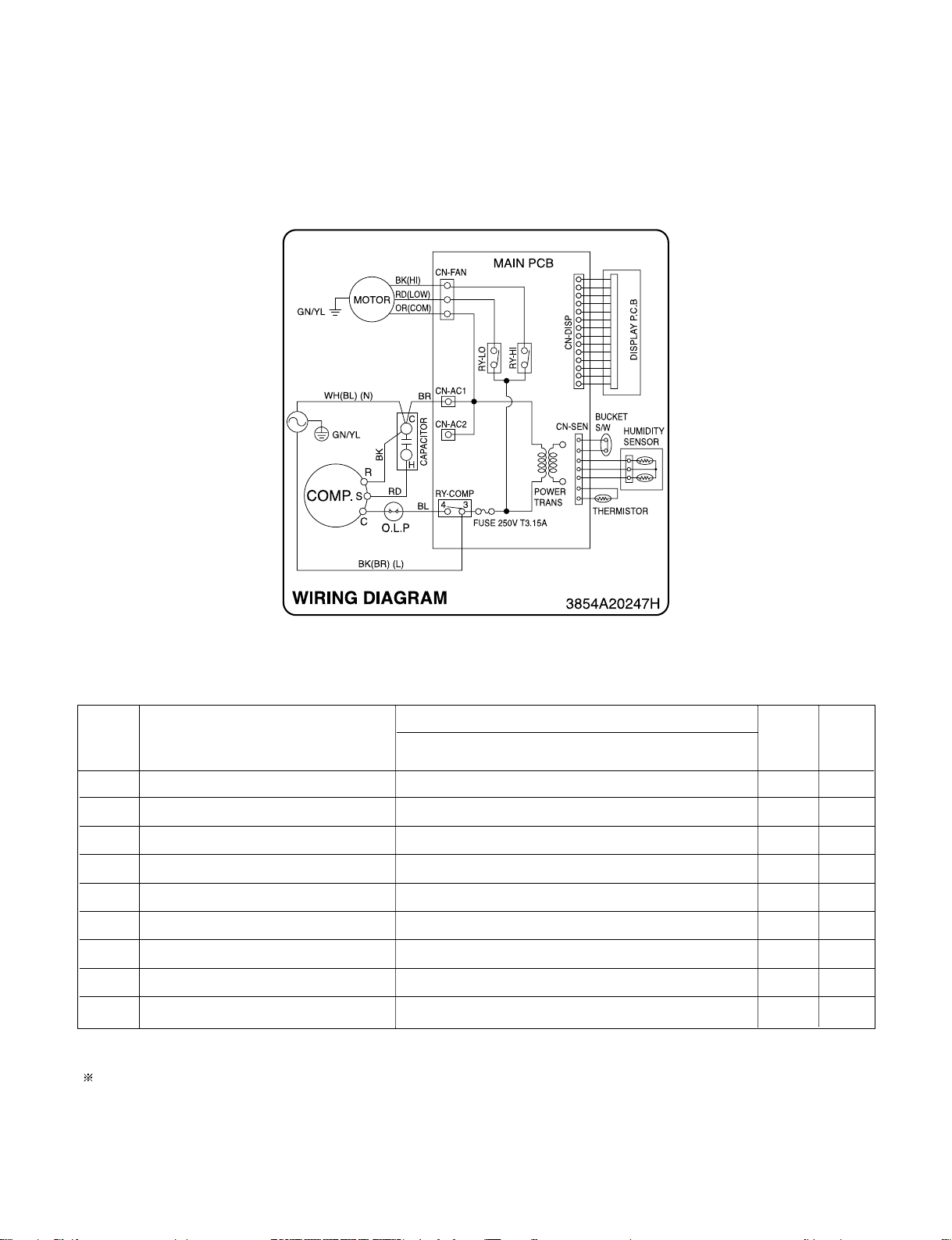
• MODEL : DH300EY7
S: SERVICE PARTS A: ALTERNATE PARTS N: NOT SERVICE PARTS
Q'TY
PER SET
1
1
1
1
1
1
1
1
1
RE-
MARKS
S
S
S
S
S
S
S
S
S
1
2
3
4
5
6
7
8
9
DESCRIPTION
POWER CORD ASSEMBLY
MOTOR ASSEMBLY
CAPACITOR
COMPRESSOR, SET
OLP
PWB(PCB) ASSEMBLY, DISPLAY
SENSOR ASSEMBLY
SWITCH ASSEMBLY, MICRO
PWB(PCB) ASSEMBLY, MAIN
DH300EY7
6411A20001Z
4681A20040Q
0CZZA20005J
2520UCBS005
6750U-L082A
6871A20600A
6877A30013L
6600A30003C
6871A20888A
PART NO.
NO.
—10—
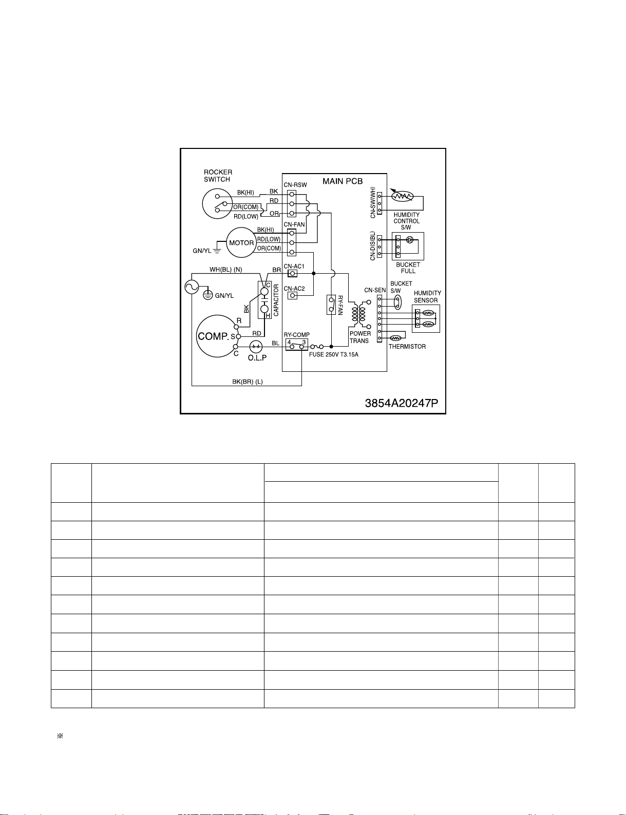
• MODEL :DH400MY7/LD40Y7
Q'TY
PER SET
1
1
1
1
1
1
1
1
1
1
1
RE-
MARKS
S
S
S
S
S
S
S
S
S
S
S
1
2
3
4
5
6
7
8
9
10
11
DESCRIPTION
POWER CORD ASSEMBLY
SWITCH, ROCKER
MOTOR ASSEMBLY
CAPACITOR
COMPRESSOR (ROTARY), SET
OLP (ASSEMBLY)
PWB(PCB) ASSEMBLY, DISPLAY
SENSOR ASSEMBLY
SWITCH ASSEMBLY, ROTARY
SWITCH ASSEMBLY, MICRO
PWB(PCB) ASSEMBLY, MAIN
DH400MY7/LD40Y7
6411A20001Z
6600FX5001G
4681A20040Q
0CZZA20005N
2520UCAS003
6750U-L103A
6871A20289B
6877A30013L
6601A30006A
6600A30003C
6871A10142A
PART NO.
S: SERVICE PARTS A: ALTERNATE PARTS N: NOT SERVICE PARTS
NO.
—11—
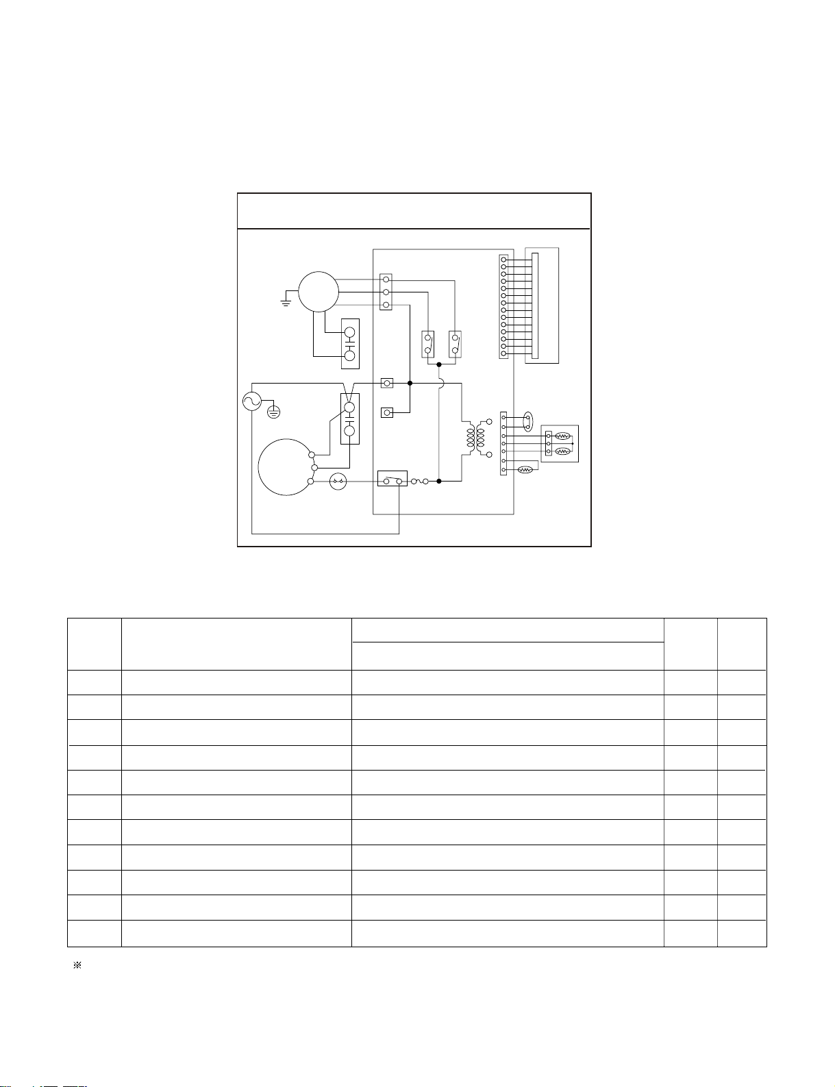
• MODEL :DH404EY7/DH400EY7/LD40EY7
Q'TY
PER SET
1
1
1
1
1
1
1
1
1
RE-
MARKS
S
S
S
S
S
S
S
S
S
NO.
1
POWER CORD ASSEMBLY
2
MOTOR ASSEMBLY
3
CAPACITOR
4
COMPRESSOR,SET
5
OLP
6
PWB(PCB) ASSEMBLY,DISPLAY
7
SENSOR ASSEMBLY
8
SWITCH ASSEMBLY,MICRO
9
PWB(PCB) ASSEMBLY,MAIN
S: SERVICE PARTS A: ALTERNATE PARTS N: NOT SERVICE PARTS
DESCRIPTION
DH404EY7/DH400EY7
PART NO.
LD40EY7
6411A20001Z
4681A20040Q
0CZZA20005N
TBZ30871801
EAF35787201
6871A20600A
6877A30013L
6600A30003C
6871A20888A
—12—
• MODEL :DH500MY7
Q'TY
PER SET
1
1
1
1
1
1
1
1
1
1
1
RE-
MARKS
S
S
S
S
S
S
S
S
S
S
S
1
2
3
4
5
6
7
8
9
10
11
DESCRIPTION
POWER CORD ASSEMBLY
SWITCH, ROCKER
MOTOR ASSEMBLY
CAPACITOR
COMPRESSOR (ROTARY), SET
OLP (ASSEMBLY)
PWB(PCB) ASSEMBLY, DISPLAY
SENSOR ASSEMBLY
SWITCH ASSEMBLY, ROTARY
SWITCH ASSEMBLY, MICRO
PWB(PCB) ASSEMBLY, MAIN
DH500MY7
6411A20001Z
6600FX5001G
4681A20040J
0CZZA20005J
2520UCBA010
6750U3L001A
6871A20289B
6877A30013L
6601A30006A
6600A30003C
6871A10142A
PART NO.
S: SERVICE PARTS A: ALTERNATE PARTS N: NOT SERVICE PARTS
NO.
—13—
• MODEL : DH504ELY7
WIRINGWIRING
BK(HI)
RD(LOW)
MOTOR
YL
WH
K
B
R
S
C
O.L.P
BK(BR) (L)
OR(COM)
RD
GN/YL
WH(BL) (N)
GN/YL
COMP.
F
C
C
H
BR
BL
RO
T
ICA
P
AC
RO
T
ICA
P
AC
DIA GRAMDIA GRAM
OL-Y
R
AC1
AC2
FUSE 250V T3.15A
MAIN PCB
IH-YR
POWER
TRANS
CN-SEN
CN-FAN
CN-
CN-
RY-COMP
4 3
PSID-NC
BUCKET
S/W
HUMIDITY
SENSOR
THERMIS
TOR
3854A20247V3854A2024
B.C.P YALPSID
7V
NO.
DESCRIPTION
PART NO.
DH504ELY7
1
2
3
4
5
6
7
8
9
10
11
POWER CORD ASSEMBLY
MOTOR ASSEMBLY
CAPACITOR
CAPACITOR
COMPRESSOR (ROTARY), SET
OLP.
PWB(PCB) ASSEMBLY, DISPLAY
SENSOR ASSEMBLY
SWITCH ASSEMBLY, MICRO
PWB(PCB) ASSEMBLY, MAIN
COIL ASSEMBLY, SOLENOID
6411A20001Z
EAU32357501
0CZZA20005J
3H00660V
2520UCBA010
6750U3L001A
6871A20600A
6877A30013L
6600A30003C
6871A20888A
6421A20003K
S: SERVICE PARTS A: ALTERNATE PARTS N: NOT SERVICE PARTS
Q'TY
PER SET
1
1
1 S
1
1
1
1
1
1
1
1
RE-
MARKS
S
S
S
S
S
S
S
S
S
S
 Loading...