


 Loading...
Z390 UD
User's Manual
Rev. 1001
12ME-Z39UD-1001R
For more product details, please visit GIGABYTE's website.
To reduce the impacts on global warming, the packaging materials of this product are recyclable and reusable. GIGABYTE works with you to protect the environment.

Motherboard
Z390 UD
Motherboard
Z390 UD
Aug. 25, 2018

 Aug. 25, 2018
Copyright
© 2018 GIGA-BYTE TECHNOLOGY CO., LTD. All rights reserved.
The trademarks mentioned in this manual are legally registered to their respective owners.
Disclaimer
Information in this manual is protected by copyright laws and is the property of GIGABYTE.
Changestothespecifications andfeaturesinthis manualmaybemadebyGIGABYTEwithout priornotice.
No part of this manual may be reproduced, copied, translated, transmitted, or published in any form or by any means without GIGABYTE's prior written permission.
In order to assist in the use of this product, carefully read the User's Manual.
For product-related information, check on our website at: https://www.gigabyte.com
Identifying Your Motherboard Revision
The revision number on your motherboard looks like this: "REV: X.X." For example, "REV: 1.0" means the revision of the motherboard is 1.0. Check your motherboard revision before updating motherboard BIOS, drivers, or when looking for technical information.
Example:

Table of Contents
Z390 UD Motherboard Layout.......................................................................................... |
4 |
|
Chapter 1 Hardware Installation...................................................................................... |
5 |
|
1-1 |
Installation Precautions..................................................................................... |
5 |
1-2 |
Product Specifications...................................................................................... |
6 |
1-3 |
Installing the CPU............................................................................................. |
9 |
1-4 |
Installing the Memory........................................................................................ |
9 |
1-5 Installing an Expansion Card.......................................................................... |
10 |
|
1-6 |
Back Panel Connectors.................................................................................. |
10 |
1-7 |
Internal Connectors........................................................................................ |
12 |
Chapter 2 BIOS Setup................................................................................................... |
20 |
|
2-1 |
Startup Screen................................................................................................ |
20 |
2-2 |
The Main Menu............................................................................................... |
21 |
2-3 |
M.I.T................................................................................................................ |
22 |
2-4 |
System............................................................................................................ |
28 |
2-5 |
BIOS............................................................................................................... |
29 |
2-6 |
Peripherals...................................................................................................... |
32 |
2-7 |
Chipset............................................................................................................ |
35 |
2-8 |
Power.............................................................................................................. |
36 |
2-9 |
Save & Exit..................................................................................................... |
38 |
Chapter 3 Appendix....................................................................................................... |
39 |
|
3-1 Configuring a RAID Set.................................................................................. |
39 |
|
3-2 Installing an Intel® Optane™ Memory.............................................................. |
41 |
|
3-3 |
Drivers Installation.......................................................................................... |
43 |
Regulatory Statements.............................................................................................. |
44 |
|
Contact Us................................................................................................................. |
48 |
|
- 3 -
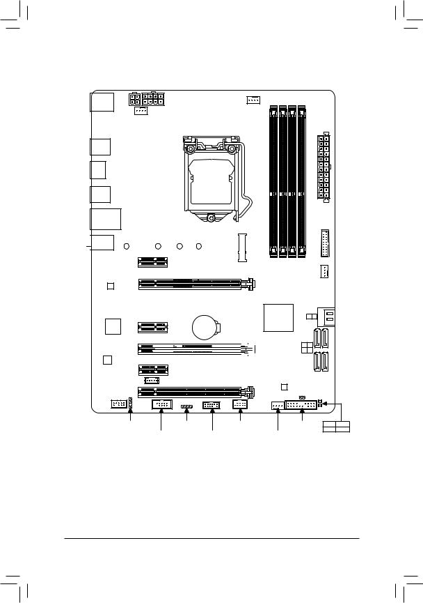
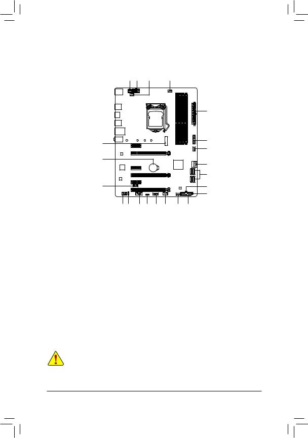
Z390 UD Motherboard Layout
KB_MS
R_USB30_1
HDMI
R_USB30_2
USB30_LAN

 AUDIO
AUDIO
Realtek®
GbE LAN
ATX_12V_2X2
110
ATX_12V_2X4
SYS_FAN1 |
|
CPU_FAN |
|
|
|
|
LGA1151 |
ATX |
|
|
80 |
60 |
42 |
M2A |
|
|
USB30F |
|
|
|
|
|||
PCIEX1_1 |
|
|
DDR4B1 |
DDR4B2 DDR4A1 |
DDR4A2 |
FAN2SYS |
PCIEX16 |
|
Z390 UD |
||||
|
|
|
|
|
||
|
|
|
|
|
|
iTE® |
PCIEX1_2 |
|
BAT |
||
Super I/O |
Intel® Z390
SATA3 1 0
PCIEX4_1
CODEC 

 PCIEX1_3
SATA3 |
5 42 |
|
3 |
|
THB_C |
|
|
M_BIOS |
|
|
|
PCIEX4_2 |
|
|
CLR_CMOS |
|
|
|
F_AUDIO |
|
|
|
|
|
|
|
|
|
|
|
|
|
SPDIF_O |
LED_C |
F_USB |
F_PANEL CPU |
DRAM |
|
|
COM |
|
TPM |
SYS_FAN3 |
VGA |
BOOT |
|
|
|
|
|||
Box Contents |
|
|
|
|
|
|
55 |
Z390 UD motherboard |
|
55 Two SATA cables |
|
|
|
55 |
Motherboard driver disk |
|
55 I/O Shield |
|
|
|
55 |
User's Manual |
|
|
|
|
|
*The box contents above are for reference only and the actual items shall depend on the product package you obtain. The box contents are subject to change without notice.
-4 -

Chapter 1 Hardware Installation
1-1 Installation Precautions
The motherboard contains numerous delicate electronic circuits and components which can become damaged as a result of electrostatic discharge (ESD). Prior to installation, carefully read the user's manual and follow these procedures:
•• Prior to installation, make sure the chassis is suitable for the motherboard.
•• Prior to installation, do not remove or break motherboard S/N (Serial Number) sticker or warranty sticker provided by your dealer. These stickers are required for warranty validation.
•• Always remove the AC power by unplugging the power cord from the power outlet before installing or removing the motherboard or other hardware components.
•• When connecting hardware components to the internal connectors on the motherboard, make sure they are connected tightly and securely.
•• When handling the motherboard, avoid touching any metal leads or connectors.
•• It is best to wear an electrostatic discharge (ESD) wrist strap when handling electronic components such as a motherboard, CPU or memory. If you do not have an ESD wrist strap, keep your hands dry and first touch a metal object to eliminate static electricity.
•• Prior to installing the motherboard, please have it on top of an antistatic pad or within an electrostatic shielding container.
•• Before connecting or unplugging the power supply cable from the motherboard, make sure the power supply has been turned off.
•• Before turning on the power, make sure the power supply voltage has been set according to the local voltage standard.
•• Before using the product, please verify that all cables and power connectors of your hardware components are connected.
•• To prevent damage to the motherboard, do not allow screws to come in contact with the motherboard circuit or its components.
•• Make sure there are no leftover screws or metal components placed on the motherboard or within the computer casing.
•• Do not place the computer system on an uneven surface.
•• Do not place the computer system in a high-temperature or wet environment.
•• Turning on the computer power during the installation process can lead to damage to system components as well as physical harm to the user.
•• If you are uncertain about any installation steps or have a problem related to the use of the product, please consult a certified computer technician.
•• If you use an adapter, extension power cable, or power strip, ensure to consult with its installation and/or grounding instructions.
- 5 -
1-2 |
Product Specifications |
|
|
|
|
|
CPU |
Support for Intel 9000 processors and 8th Generation Intel® Core™ i7 processors/ |
|
|
Intel® Core™ i5 processors/Intel® Core™ i3 processors/Intel® Pentium® processors/ |
|
|
Intel® Celeron® processors in the LGA1151 package |
|
|
(Go to GIGABYTE's website for the latest CPU support list.) |
|
|
L3 cache varies with CPU |
|
Chipset |
Intel® Z390 Express Chipset |
|
Memory |
4 x DDR4 DIMM sockets supporting up to 64 GB of system memory |
|
|
Dual channel memory architecture |
|
|
Support for DDR4 2666/2400/2133 MHz memory modules |
|
|
Support for ECC Un-buffered DIMM 1Rx8/2Rx8 memory modules (operate in |
|
|
non-ECC mode) |
|
|
Support for non-ECC Un-buffered DIMM 1Rx8/2Rx8/1Rx16 memory modules |
|
|
Support for Extreme Memory Profile (XMP) memory modules |
|
|
(Go to GIGABYTE's website for the latest supported memory speeds and memory |
|
|
modules.) |
|
Onboard |
Integrated Graphics Processor-Intel® HD Graphics support: |
|
Graphics |
- 1 x HDMI port, supporting a maximum resolution of 4096x2160@30 Hz |
* Support for HDMI 1.4 version and HDCP 2.2.
Maximum shared memory of 1 GB
Audio |
|
Realtek® ALC887 codec |
|
High Definition Audio |
|
|
|
2/4/5.1/7.1-channel |
*To configure 7.1-channel audio, you have to use an HD front panel audio module and enable the multi-channel audio feature through the audio driver.
Support for S/PDIF Out
LAN |
Realtek® GbE LAN chip (10/100/1000 Mbit) |
|
Expansion Slots |
1 x PCI Express x16 slot, running at x16 (PCIEX16) |
|
|
|
* For optimum performance, if only one PCI Express graphics card is to be installed, |
|
|
be sure to install it in the PCIEX16 slot. |
|
2 x PCI Express x16 slots, running at x4 (PCIEX4_1/PCIEX4_2) |
|
|
3 x PCI Express x1 slots |
|
|
(All of the PCI Express slots conform to PCI Express 3.0 standard.) |
|
Multi-Graphics |
Support for AMD Quad-GPU CrossFire™ and 2-Way AMD CrossFire™ technologies |
|
Technology |
|
|
Storage |
Chipset: |
|
Interface |
- |
1 x M.2 connector (Socket 3, M key, type 2242/2260/2280/22110 SATA and |
|
|
PCIe x4/x2 SSD support, prepared for Intel® Hybrid SSD) |
-6 x SATA 6Gb/s connectors
-Support for RAID 0, RAID 1, RAID 5, and RAID 10
* Refer to "1-7 Internal Connectors," for the installation notices for the M.2 and SATA connectors.
Intel® Optane™ Memory Ready
- 6 -
USB |
|
Chipset: |
|
|
- 8 x USB 3.1 Gen 1 ports (6 ports on the back panel, 2 ports available through |
|
|
the internal USB header) |
|
|
- 2 x USB 2.0/1.1 ports available through the internal USB header |
Internal |
|
1 x 24-pin ATX main power connector |
Connectors |
|
1 x 8-pin ATX 12V power connector |
|
1 x 4-pin ATX 12V power connector |
|
|
1 x M.2 Socket 3 connector |
|
|
6 x SATA 6Gb/s connectors |
|
|
1 x CPU fan header |
|
|
3 x system fan headers |
|
|
1 x RGB LED strip header |
|
|
1 x front panel header |
|
|
1 x front panel audio header |
|
|
1 x USB 3.1 Gen 1 header |
|
|
1 x USB 2.0/1.1 header |
|
|
1 x S/PDIF Out header |
|
|
1 x Thunderbolt™ add-in card connector |
|
|
1 x Trusted Platform Module (TPM) header (2x6 pin, for the GC-TPM2.0_S |
|
|
|
module only) |
|
1 x serial port header |
|
|
1 x Clear CMOS jumper |
|
Back Panel |
|
1 x PS/2 mouse port |
Connectors |
|
1 x PS/2 Keyboard port |
|
1 x HDMI port |
|
|
6 x USB 3.1 Gen 1 ports |
|
|
1 x RJ-45 port |
|
|
3 x audio jacks |
|
I/O Controller |
|
iTE® I/O Controller Chip |
Hardware |
|
Voltage detection |
Monitor |
|
Temperature detection |
|
Fan speed detection |
|
|
|
Overheating warning |
|
Fan fail warning |
|
|
Fan speed control |
|
*Whether the fan speed control function is supported will depend on the fan you install.
BIOS |
|
1 x 128 Mbit flash |
|
Use of licensed AMI UEFI BIOS |
|
|
|
PnP 1.0a, DMI 2.7, WfM 2.0, SM BIOS 2.7, ACPI 5.0 |
- 7 -
Unique Features |
|
Support for APP Center |
||
|
|
|
* Available applications in APP Center may vary by motherboard model. Supported |
|
|
|
|
functionsofeachapplicationmayalsovarydependingonmotherboardspecifications. |
|
|
|
- |
3D OSD |
|
|
|
- |
@BIOS |
|
|
|
- |
AutoGreen |
|
|
|
- |
Ambient LED |
|
|
|
- |
Cloud Station |
|
|
|
- |
EasyTune |
|
|
|
- |
Easy RAID |
|
|
|
- |
Fast Boot |
|
|
|
- |
Game Boost |
|
|
|
- |
ON/OFF Charge |
|
|
|
- |
Platform Power Management |
|
|
|
- |
Smart Backup |
|
|
|
- |
Smart Keyboard |
|
|
|
- |
Smart TimeLock |
|
|
|
- |
Smart HUD |
|
|
|
- |
System Information Viewer |
|
|
|
- |
Smart Survey |
|
|
|
- |
USB Blocker |
|
|
|
Support for Q-Flash |
||
|
Support for Xpress Install |
|||
Bundled |
|
Norton® Internet Security (OEM version) |
||
Software |
|
Realtek® 8118 Gaming LAN Bandwidth Control Utility |
||
Operating |
Support for Windows 10 64-bit |
|||
System |
||||
|
|
|
||
Form Factor |
|
ATX Form Factor; 30.5cm x 23.0cm |
||
*GIGABYTE reserves the right to make any changes to the product specifications and product-related information without prior notice.
Please visit GIGABYTE's website for support lists of CPU, memory modules, SSDs, and M.2 devices.
- 8 -
Please visit the Support\Utility List page on GIGABYTE's website to download the latest version of apps.
1-3 |
Installing the CPU |
|
|
Read the following guidelines before you begin to install the CPU: |
|
|
•• |
Make sure that the motherboard supports the CPU. |
|
|
(Go to GIGABYTE's website for the latest CPU support list.) |
|
•• |
Always turn off the computer and unplug the power cord from the power outlet before installing the |
|
•• |
CPU to prevent hardware damage. |
|
Locate the pin one of the CPU. The CPU cannot be inserted if oriented incorrectly. (Or you may |
|
|
•• |
locate the notches on both sides of the CPU and alignment keys on the CPU socket.) |
|
Apply an even and thin layer of thermal grease on the surface of the CPU. |
|
|
•• |
Do not turn on the computer if the CPU cooler is not installed, otherwise overheating and damage |
|
•• |
of the CPU may occur. |
|
Set the CPU host frequency in accordance with the CPU specifications. It is not recommended |
|
|
|
that the system bus frequency be set beyond hardware specifications since it does not meet the |
|
|
standard requirements for the peripherals. If you wish to set the frequency beyond the standard |
|
|
specifications, please do so according to your hardware specifications including the CPU, graphics |
|
|
card, memory, hard drive, etc. |
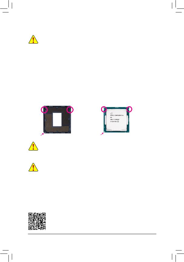
Installing the CPU
Locate the alignment keys on the motherboard CPU socket and the notches on the CPU.
LGA1151 CPU Socket |
|
|
LGA1151 CPU |
Alignment Key |
Alignment Key |
Notch |
Notch |
Pin One Corner of the CPU Socket |
Triangle Pin One Marking on the CPU |
Do not remove the CPU socket cover before inserting the CPU. It may pop off from the load plate automatically during the process of re-engaging the lever after you insert the CPU.
1-4 Installing the Memory
Read the following guidelines before you begin to install the memory:
•• Make sure that the motherboard supports the memory. It is recommended that memory of the same capacity, brand, speed, and chips be used.
(Go to GIGABYTE's website for the latest supported memory speeds and memory modules.)
•• Always turn off the computer and unplug the power cord from the power outlet before installing the memory to prevent hardware damage.
•• Memory modules have a foolproof design. A memory module can be installed in only one direction. If you are unable to insert the memory, switch the direction.
Dual Channel Memory Configuration
This motherboard provides four memory sockets and supports Dual Channel Technology. After the memory is installed, the BIOS will automatically detect the specifications and capacity of the memory. Enabling Dual
Channel memory mode will double the original memory bandwidth.
Please visit GIGABYTE's website for details on hardware installation.
- 9 -

The four memory sockets are divided into two channels and each channel has two memory sockets as following:
Channel A: DDR4_A1, DDR4_A2Channel B: DDR4_B1, DDR4_B2
Dual Channel Memory Configurations Table
|
DDR4_B1 |
DDR4_B2 |
DDR4_A1 |
DDR4_A2 |
2 Modules |
- - |
DS/SS |
- - |
DS/SS |
|
DS/SS |
- - |
DS/SS |
- - |
4 Modules |
DS/SS |
DS/SS |
DS/SS |
DS/SS |
(SS=Single-Sided, DS=Double-Sided, "- -"=No Memory)
Due to CPU limitations, read the following guidelines before installing the memory in Dual Channel mode.
1.Dual Channel mode cannot be enabled if only one memory module is installed.
2.When enabling Dual Channel mode with two or four memory modules, it is recommended that memory of the same capacity, brand, speed, and chips be used.
1-5 Installing an Expansion Card
Read the following guidelines before you begin to install an expansion card:
•• Make sure the motherboard supports the expansion card. Carefully read the manual that came with your expansion card.
•• Always turn off the computer and unplug the power cord from the power outlet before installing an expansion card to prevent hardware damage.
1-6 Back Panel Connectors
PS/2 Keyboard and PS/2 Mouse Port
Use the upper port (green) to connect a PS/2 mouse and the lower port (purple) to connect a PS/2 keyboard.
 USB 3.1 Gen 1 Port
The USB 3.1 Gen 1 port supports the USB 3.1 Gen 1 specification and is compatible to the USB 2.0 specification. Use this port for USB devices.
HDMI Port
 The HDMI port supports HDCP 2.2 and Dolby TrueHD and DTS HD Master


 Audio formats. It also supports up to 192KHz/16bit 8-channel LPCM audio output. You can use this port to connect your HDMI-supported monitor. The maximum supported resolution is 4096x2160@30 Hz, but the actual resolutions supported are dependent on the monitor being used.
After installing the HDMI device, make sure to set the default sound playback device to HDMI. (The item name may differ depending on your operating system.)
- 10 -
RJ-45 LAN Port
The Gigabit Ethernet LAN port provides Internet connection at up to 1 Gbps data rate. The following describes the states of the LAN port LEDs.
Connection/ |
|
|
|
|
|
|
|
Connection/Speed LED: |
|
Activity LED: |
|
||||||
Speed LED |
|
|
|
Activity LED |
|
|
|||||||||||
|
|
|
|
|
|
|
|||||||||||
|
|
|
|
|
|
|
|
|
|
|
|
|
State |
Description |
|
State |
Description |
|
|
|
|
|
|
|
|
|
|
|
|
|
Orange |
1 Gbps data rate |
|
Blinking |
Data transmission or receiving is occurring |
|
|
|
|
|
|
|
|
|
|
|
|
|
Green |
100 Mbps data rate |
|
Off |
No data transmission or receiving is occurring |
|
|
|
|
|
|
|
|
|
|
|
|
|
Off |
10 Mbps data rate |
|
||
|
|
|
|
|
|
|
|
|
|
|
|
|
|
|
|
||
|
|
|
LAN Port |
|
|
|
|||||||||||
|
|
|
|
|
|
|
|
||||||||||
Line In/Rear Speaker Out (Blue)
The line in jack. Use this audio jack for line in devices such as an optical drive, walkman, etc.
 Line Out/Front Speaker Out (Green)
The line out jack.
Mic In/Center/Subwoofer Speaker Out (Pink)
The Mic in jack.
Audio Jack Configurations:
Jack |
Headphone/ |
4-channel |
5.1-channel |
7.1-channel |
|
2-channel |
|||||
|
|
|
|
||
Line In/Rear Speaker Out |
|
a |
a |
a |
|
|
|
|
|
|
|
Line Out/Front Speaker Out |
a |
a |
a |
a |
|
|
|
|
|
|
|
Mic In/Center/Subwoofer Speaker Out |
|
|
a |
a |
|
|
|
|
|
|
|
Front Panel Line Out/Side Speaker Out |
|
|
|
a |
|
|
|
|
|
|
To configure 7.1-channel audio, you have to use an HD front panel audio module and enable the multi-channel audio feature through the audio driver.
•• When removing the cable connected to a back panel connector, first remove the cable from your device and then remove it from the motherboard.
•• When removing the cable, pull it straight out from the connector. Do not rock it side to side to prevent an electrical short inside the cable connector.
Please visit GIGABYTE's website for details on configuring the audio software.
- 11 -
1-7 Internal Connectors |
|
|
|
1 |
1 |
4 |
3 |
|
|
|
2 |
7 |
|
|
11 |
|
|
4 |
|
|
|
|
|
16 |
|
|
6 |
|
|
|
|
|
|
|
6 |
15 |
|
|
17 |
|
|
|
18 |
9 |
10 |
14 |
5 |
13 |
12 |
4 |
8 |
1) |
ATX_12V_2X2/ATX_12V_2X4 |
10) |
SPDIF_O |
2) |
ATX |
11) |
F_USB30 |
3) |
CPU_FAN |
12) |
F_USB |
4) |
SYS_FAN1/2/3 |
13) |
TPM |
5) |
LED_C |
14) |
COM |
6) |
SATA3 0/1/2/3/4/5 |
15) |
THB_C |
7) |
M2A |
16) |
BAT |
8) |
F_PANEL |
17) |
CLR_CMOS |
9) |
F_AUDIO |
18) |
CPU/DRAM/VGA/BOOT |
Read the following guidelines before connecting external devices:
•• First make sure your devices are compliant with the connectors you wish to connect.
•• Before installing the devices, be sure to turn off the devices and your computer. Unplug the power cord from the power outlet to prevent damage to the devices.
•• After installing the device and before turning on the computer, make sure the device cable has been securely attached to the connector on the motherboard.
- 12 -
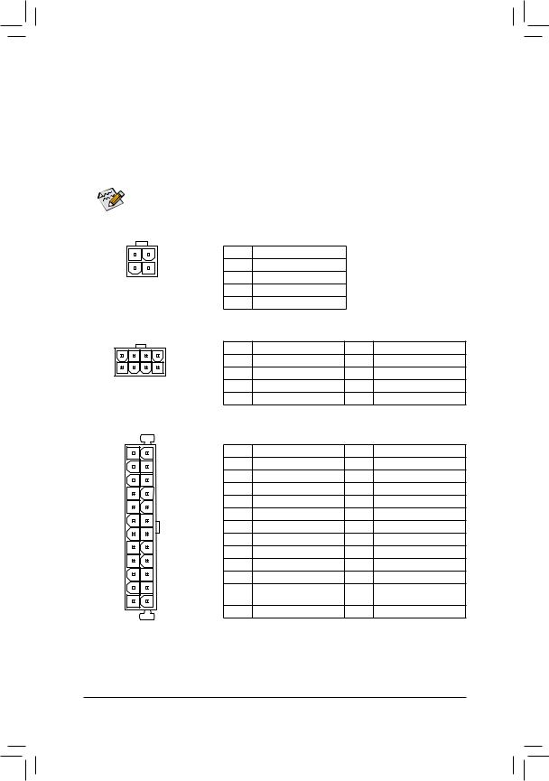
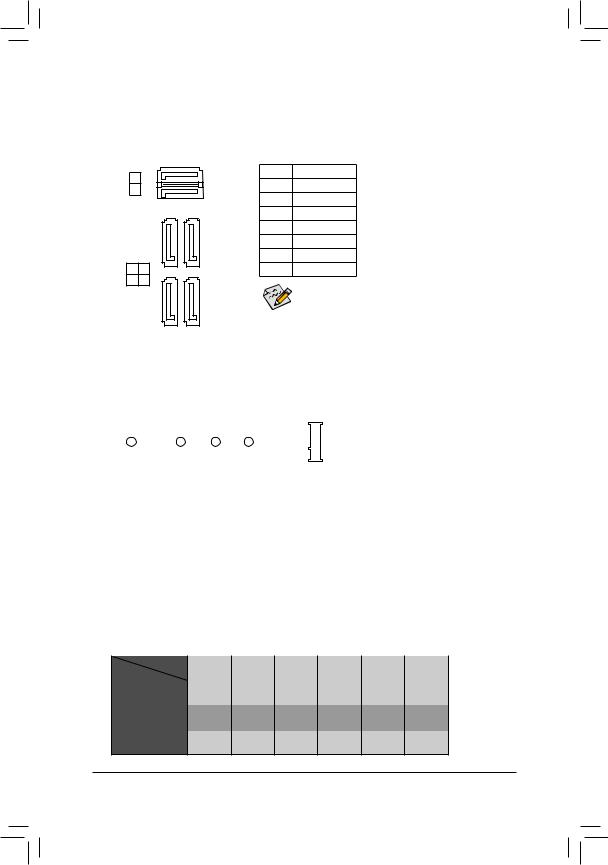
1/2) ATX_12V_2X2/ATX_12V_2X4/ATX (2x4, 2x2, 12V Power Connectors and 2x12 Main
Power Connector)
With the use of the power connector, the power supply can supply enough stable power to all the components on the motherboard. Before connecting the power connector, first make sure the power supply is turned off and all devices are properly installed. The power connector possesses a foolproof design. Connect the power supply cable to the power connector in the correct orientation.
The 12V power connector mainly supplies power to the CPU. If the 12V power connector is not connected, the computer will not start.
To meet expansion requirements, it is recommended that a power supply that can withstand high power consumption be used (500W or greater). If a power supply is used that does not provide the required power, the result can lead to an unstable or unbootable system.
34
12
ATX_12V_2X2
5 |
8 |
1 |
4 |
|
ATX_12V_2X4 |
12 24
1 |
13 |
ATX
ATX_12V_2X2:
Pin No. Definition
1GND
2GND
3+12V
4+12V
ATX_12V_2X4: |
|
|
|
Pin No. |
Definition |
Pin No. |
Definition |
1 |
GND (Only for 2x4-pin 12V) |
5 |
+12V (Only for 2x4-pin 12V) |
2 |
GND (Only for 2x4-pin 12V) |
6 |
+12V (Only for 2x4-pin 12V) |
3 |
GND |
7 |
+12V |
4 |
GND |
8 |
+12V |
ATX: |
|
|
|
Pin No. |
Definition |
Pin No. |
Definition |
1 |
3.3V |
13 |
3.3V |
2 |
3.3V |
14 |
-12V |
3 |
GND |
15 |
GND |
4 |
+5V |
16 |
PS_ON (soft On/Off) |
5 |
GND |
17 |
GND |
6 |
+5V |
18 |
GND |
7 |
GND |
19 |
GND |
8 |
Power Good |
20 |
NC |
9 |
5VSB (stand by +5V) |
21 |
+5V |
10 |
+12V |
22 |
+5V |
11 |
+12V (Only for 2x12-pin |
23 |
+5V (Only for 2x12-pin ATX) |
|
ATX) |
|
|
12 |
3.3V (Only for 2x12-pin ATX) |
24 |
GND (Only for 2x12-pin ATX) |
- 13 -
3/4) CPU_FAN/SYS_FAN1/2/3 (Fan Headers)
All fan headers on this motherboard are 4-pin. Most fan headers possess a foolproof insertion design. When connecting a fan cable, be sure to connect it in the correct orientation (the black connector wire is the ground wire). The speed control function requires the use of a fan with fan speed control design. For optimum heat dissipation, it is recommended that a system fan be installed inside the chassis.
|
|
|
|
|
|
1 |
|
|
|
Pin No. |
Definition |
|
|
|
|
|
|
|
|
|
|||
|
|
|
|
|
|
|
|
|
|
1 |
GND |
CPU_FAN/SYS_FAN1 |
|
|
|
||||||||
|
|
|
|
|
|
|
|
|
|
2 |
Voltage Speed Control |
1 |
|
|
|
|
|
|
|
|
1 |
3 |
Sense |
|
|
|
|
|
|
|
|
|
|
|
|
SYS_FAN2 |
4 |
PWM Speed Control |
|||||||||
|
|
|
|
|
|
|
|
|
|
|
|
|
|
|
|
|
|
|
|
|
|
|
|
SYS_FAN3
•• Be sure to connect fan cables to the fan headers to prevent your CPU and system from overheating. Overheating may result in damage to the CPU or the system may hang.
•• Thesefanheadersarenotconfigurationjumperblocks.Donotplaceajumpercapontheheaders.
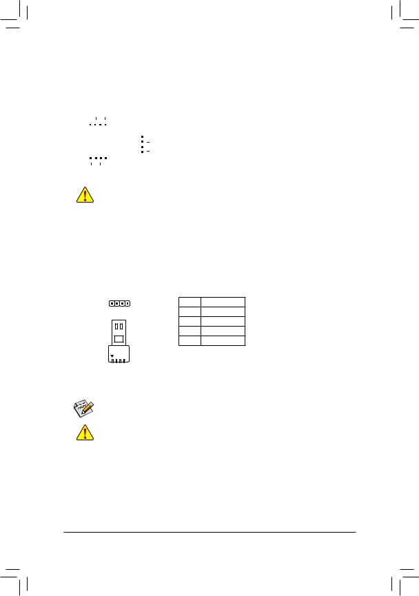
5)LED_C (RGB LED Strip Header)
The header can be used to connect a standard 5050 RGB LED strip (12V/G/R/B), with maximum power rating of 2A (12V) and maximum length of 2m.
1
RGB
LED Strip
1 
12V
Pin No. |
Definition |
1 |
12V |
2 |
G |
3 |
R |
4 |
B |
Connect your RGB LED strip to the header. The power pin (marked with a triangle on the plug) of the LED strip must be connected to Pin 1 (12V) of the digital LED strip header. Incorrect connection may lead to the damage of the LED strip.
For how to turn on/off the lights of the LED strip please visit the "Unique Features" webpage of
GIGABYTE's website.
Before installing the devices, be sure to turn off the devices and your computer. Unplug the power cord from the power outlet to prevent damage to the devices.
- 14 -
6)SATA3 0/1/2/3/4/5 (SATA 6Gb/s Connectors)
The SATA connectors conform to SATA 6Gb/s standard and are compatible with SATA 3Gb/s and SATA 1.5Gb/s standard. Each SATA connector supports a single SATA device. The Intel® ChipsetsupportsRAID0, RAID 1, RAID 5, and RAID 10. Refer to Chapter 3, "Configuring a RAID Set," for instructions on configuring a RAID array.
SATA3 |
1 |
7 |
|
1 |
Pin No. |
Definition |
|
1 |
GND |
||||
|
|
|
||||
0 |
7 |
|
1 |
|||
|
|
2 |
TXP |
|||
|
|
|
|
|
||
|
|
1 |
1 |
|
3 |
TXN |
|
|
|
|
|
4 |
GND |
|
|
|
|
|
5 |
RXN |
|
|
|
|
|
6 |
RXP |
SATA3 |
3 |
2 |
|
|
7 |
GND |
|
5 |
4 |
|
|
|
To enable hot-plugging for the SATA ports, refer to |
|
|
|
|
|
|
|
|
|
|
|
|
|
Chapter 2, "BIOS Setup," "Peripherals\SATA And RST |
|
|
|
|
|
|
Configuration," for more information. |
77
7)M2A (M.2 Socket 3 Connector)
The M.2 connector supports M.2 SATA SSDs or M.2 PCIe SSDs and support RAID configuration. Please note that an M.2 PCIe SSD cannot be used to create a RAID set either with an M.2 SATA SSD or a SATA hard drive. To create a RAID array with an M.2 PCIe SSD, you must set up the configuration in UEFI BIOS mode. Refer to Chapter 3, "Configuring a RAID Set," for instructions on configuring a RAID array.
110 |
80 |
60 |
42 |
Follow the steps below to correctly install an M.2 SSD in the M.2 connector. Step 1:
Use a screw driver to unfasten the screw and nut from the motherboard. Locate the proper mounting hole for the M.2 SSD to be installed and then screw the nut first.
Step 2:
Slide the M.2 SSD into the connector at an angle. Step 3:
Press the M.2 SSD down and then secure it with the screw.

 Select the proper hole for the M.2 SSD to be installed and refasten the screw and nut.
Installation Notices for the M.2 and SATA Connectors:
Due to the limited number of lanes provided by the Chipset, the availability of the SATA connectors may be affected by the type of device installed in the M.2 connector. The M2A connector shares bandwidth with the SATA3 1 connector. Refer to the following table for details.
Type of |
Connector |
SATA3 0 |
SATA3 1 |
SATA3 2 |
SATA3 3 |
SATA3 4 |
SATA3 5 |
|
|||||||
M.2 SSD |
|
|
|
|
|
|
|
M.2 SATA SSD |
a |
r |
a |
a |
a |
a |
|
|
|
|
|
|
|
|
|
M.2 PCIe SSD |
a |
a |
a |
a |
a |
a |
|
|
|
|
|
|
|
|
|
No M.2 SSD Installed |
a |
a |
a |
a |
a |
a |
|
a: Available, r: Not available
- 15 -
Loading...