


Gigabyte FA4CU, FA5DP, FA1UB, FA3DJ, FA4DJ Manual
...G-MAXTM Flex ATX Series User’s Manual
Copyright Notice
Copyright 2002 Gigabyte Technology.
All Rights Reserved. No part of this documentation, including but not limited to the products and software described in it, may be reproduced, transmitted, transcribed, stored in a
retrieval system, or translated into any language, in any form or by any means without the express written permission of Gigabyte Technology.
Tra de marks
Products and corporate names appearing in this manual may be registered trademarks or copyrights oftheir respective companies and are used only for identification or explanation
purposes without intent to infringe.
Other product names used in this manual may be trademarks or registered trademarks of their respective owners.
The author assumes no responsibility for any errors or omissions that may appear in this document nor does the author make a commitment to update the information contained herein. Third-party brands and names are the property of their respective owners.
Discla ime r
The information contained in this documentation is subject to change without notice. Gigabyte Technology makes no representations or warranties of any kind, either express or implied, with respect to the contents hereof, including but not limited to implied warranties of merchantability or fitness for a particular purpose. In no event shall Gigabyte Technology. Be liable for any loss of profits, loss of business, loss of data, interruption of business, or indirect, special, incidental, or consequential damages of any kind arising from the use of this product or documentation. Gigabyte Technology reserves the right to revise or change this product or documentation at any time without obligation of Gigabyte Technology. To notify any person of such revision or changes.
May/2002
P. E1
G-MAXTM Flex ATX Series User’s Manual
Prefa ce
This system unit is designed to be stable, safe, and easy to use. The system can be
upgraded and expanded in function easily if correct procedure is followed.
For your own safety and to avoid accidental damage to your system, please ensure you follow the following precautions:
Follow all the warnings and instructions marked on the products.
To remove or clean the product, remember to unplug the power cord.
Place your system unit in a cool, clean space, to be far away from water, heat and
dust.
Before connecting any peripheral equipment, please unplug the power cord from the
system unit to prevent unexpected damage.
The AC input supplies power to the system unit. Check your dealer if you can not recognize the type of the power supply.
CAUTION
Danger of explosion if battery is incorrectly replaced.
Replace only with the same or equivalent type recommended by the manufacture.
Dispose of used batteries according to the manufacturer’s instructions.
Introduction
G-MAXTM series product, to adopt main board of design & development by GIGABYTE that is Flex ATX mechanical design in advance, let you work smoothly in Windows environment.
Flex ATX adopt dexterous mechanical design, so it is ease by assembly & safeguard.
Specification Overview Flex ATX chassis
Flex ATX main board of GIGABYTE Power supply
DVD-ROM / CD-ROM
1.44 “FDD Power cord
Keyboard (option) Multi I/O card (option) P4 CPU cooler (option)
Assembly Box Content
Main board user’s manual User’s manual
Driver CD HDD IDE cable
Cable tie
Foot stand
Screw bag Mouse (option)
SPDIF cable (For those models with SPDIF only)
DVD Media Player
(For those models with DVD-ROM only)
P. E2

G-MAXTM Flex ATX Series User’s Manual
Ite ms included in the pa cka ge
P4 CPU cooler (Option)
PC
Sof tware and
Manuals
Ca bles |
Keyboard |
|
(Option) |
Foot Stand |
|
Mouse (Opt ion) |
|
Pow er Cord
P. E3
G-MAXTM Flex ATX Series User’s Manual
I. Cha ssis
Dimension 410(D)mm x 89(W)mm x 305(H)mm
This chassis is made with material complied with UL specification and designed for space saving and easy open with thumbscrew. There are one 5.25” and two 3.5” drive bays. This chassis complies with corresponding EMC and safety regulations.
II. Motherboard
See Motherboard Manual for details.
III. Power Supply
The ATX switching power supply included with this product supports soft off function. Hence, the system can be shut down automatically. Default input voltage setting is 230V.
Note : Please check the voltage requirements in the country you reside before turning on the PC.
IV. Syste m Component Installation
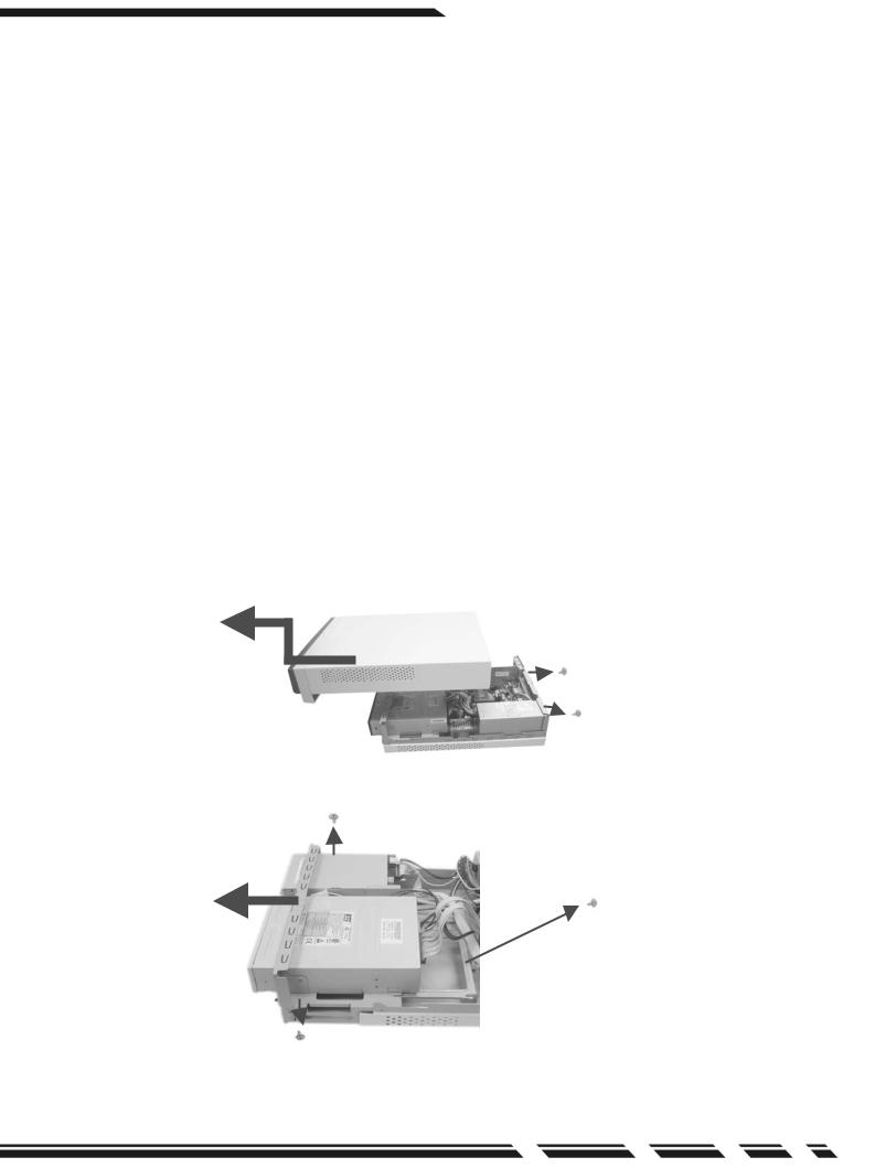
■HDD Assembly
1.Unscrew each side of the chassis and push the panel together with the uppercase toward the front.
2. Take both the screws on the front end off and pull the HDD supporting frame out.
 HDD frame
P. E4
G-MAXTM Flex ATX Series User’s Manual
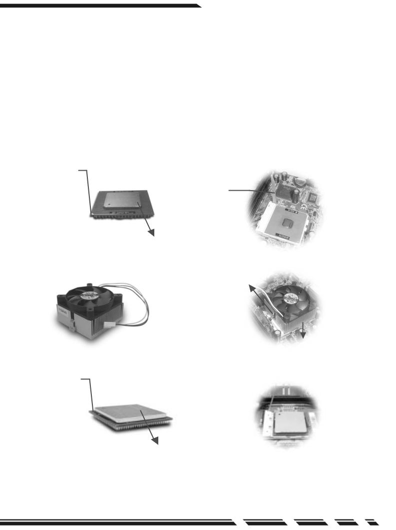
3. CPU
In this section you will find the gist of CPU installation.
3-1. Insert CPU into the CPU socket. Before installation, lift up the lever and align the cut of the CPU with the marking on the socket.
3-2. Pull down the lever to lock the CPU on the socket after installation.
3-3. Apply thermal grease to the top of the CPU. Thermal grease should cover the entire surface of the integrated heat spreader. Make sure that you should keep the cooler tight against the CPU to obtain the best cooling performance.
3-4. Connect fan power connector to CPU FAN on the motherboard.
A. For Intel Pe ntium |
and Intel Celeron proce ssors |
CPU Pin |
|
|
Lever |
Apply thermal grease to the top of the CPU properly.
Click cooler lock on the pin at sides of CPU socket.
Install cooler on top of CPU
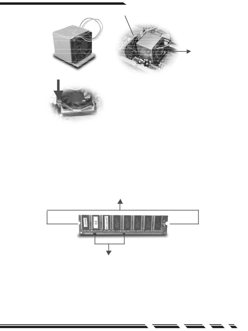
B. For Intel Pentium 4 proce ssors
CPU Pin
Lever 
Apply thermal grease to the top of the CPU properly.
P. E5
G-MAXTM Flex ATX Series User’s Manual
Power Supply
Install cooler on top of CPU
Click cooler lock  on the pin at sides
of CPU socket.
Set CPU clock frequency in BIOS Setup if needed, see Motherboard Manual for details.
4. Memory
Notches at sides of module
SDRAM
Position notches. Make sure that the notches should align the pin on memory slot on the motherboard
P. E6
 Loading...