


7VT600-RZ /
7VT600-RZ-C
AMD Athlon™ / Athlon™ XP / Duron™ Socket A Processor Motherboard
User's Manual
Rev. 1003 12ME-7VT600RZ-1003
Copyright
© 2004GIGABYT E TECHNOLOGYCO., LT D
CopyrightbyGIGA-BYTETECHNOLOGYCO.,LTD. ("GBT"). Nopart ofthismanual may bereproduced ortransmitted inanyfrom without the expressed,written permission of GBT.
Trademarks
T hird-partybrands and namesare the propertyof their respective owners.
Notice
Please do not remove anylabels on motherboard, this mayvoid the warranty of thismotherboard.
Due to rapid change in technology, some of the specifications might be out of datebefore publication of this booklet.
T he author assumes noresponsibilityfor anyerrors or omissions that mayappear in thisdocument nor does the authormake a commitmentto updatetheinformationcontained herein.

Feb. |
7VT600-RZ |
MotherBoard |
20, |
|
|
2004 |
|
|
Feb.20 ,2004 |
7VT600RZ- |
Motherboard |

Preparing Your Computer
Computer motherboards and expansion cards contain very delicate Integrated Circuit (IC) chips. To protect them against damage from static electricity, you should followsome precautions whenever you work on your computer.
1.Unplug your computer when working on the inside.
2.Use a grounded wrist strap before handling computer components. If you do not have one, touch both of your hands to a safely grounded object or to a metal object, such as the power supply case.
3.Hold components by the edges and try not touch the IC chips, leads or connectors, or other components.
4.Place components on a grounded antistatic pad or on the bag that came with the components whenever the components are separated from the system.
5.Ensure that the ATX power supply is switched off before you plug in or remove the ATX power connectoron the motherboard.
Installing the motherboard to the chassis
Ifthe motherboard hasmounting holes, buttheydon't lineup with the holes on thebase and there are no slots to attach the spacers, do not become alarmed you can still attach the spacers to the mounting holes. Just cut the bottom portion ofthe spacers (the spacer maybe a little hard to cut off, so be careful of your hands). In this way you can still attach the motherboard to the base without worrying about short circuits. Sometimes you mayneed to use the plastic springs to isolate the screw from the motherboard PCB surface, because the circuitwire may be near by the hole. Be careful, don't let the screw contact any printed circuit write or parts on the PCB that are near the fixing hole, otherwise it may damage the boardor cause boardmalfunctioning.

English
Table of Content |
|
Chapter 1 Introduction ................................................................................................ |
5 |
FeaturesSummary .............................................................................................................................. |
5 |
7VT600-RZSeries MotherboardLayout .............................................................................................. |
7 |
Block Diagram ..................................................................................................................................... |
8 |
Hardware Installation Process ............................................................................................................ |
9 |
Step 1: Set System Jumper (JP1) ...................................................................................................... |
9 |
Step 2: Install the Central Processing Unit (CPU) ........................................................................... |
10 |
Step 2-1: CPU Installation ......................................................................................................... |
10 |
Step 2-2: CPU Cooling Fan Installation .................................................................................... |
10 |
Step 3: Install Memory Modules ....................................................................................................... |
11 |
Step 4: Install Expansion Cards ....................................................................................................... |
12 |
Step 5: Install I/O Peripherals Cables .............................................................................................. |
12 |
Step 5-1: I/O Back Panel Introduction ....................................................................................... |
12 |
Step 5-2 : Connectors Introduction ............................................................................................. |
13 |
Chapter 2 BIOS Setup ............................................................................................. |
21 |
The Main Menu (For example: BIOS Ver. : F4c) ............................................................................ |
21 |
Standard CMOS Features ................................................................................................................ |
23 |
Advanced BIOS Features ................................................................................................................ |
25 |
IntegratedPeripherals ........................................................................................................................ |
26 |
PowerManagementSetup ................................................................................................................ |
28 |
PnP/PCI Configurations .................................................................................................................... |
30 |
PCI Health Status ............................................................................................................................. |
31 |
Frequency/VoltageControl ................................................................................................................ |
32 |
LoadFail-Safe Defaults ...................................................................................................................... |
34 |
LoadOptimized Defaults .................................................................................................................... |
34 |
Set Supervisor/User Password ....................................................................................................... |
35 |
Save & Exit Setup ............................................................................................................................ |
36 |
Exit Without Saving ........................................................................................................................... |
36 |
Chapter 3 Install Drivers ........................................................................................... |
37 |
7VT600-RZ Series Motherboard |
- 4 - |

Chapter 1 |
Introduction |
|
Features Summary |
||
|
|
|
CPU |
— |
Socket A processor |
|
|
AMD AthlonTM/ AthlonTM XP/ DuronTM (K7) |
|
|
128K L1 & 512K/256K/64K L2 cache on die |
|
|
200/266/333/400 MHz FSB |
|
— Supports 1.4GHz and faster |
|
|
|
|
Chipset |
— North Bridge: VIA KT600 |
|
|
— Sourth Bridge: VIA VT8235 |
|
|
|
|
Memory |
— 3 184-pin DDR sockets |
|
|
— Supports DDR DRAM PC2100/PC2700/PC3200 |
|
|
— |
Supports up to 3.0GB DDR (Max) |
|
— |
Supports only 2.5V DDR DIMM |
|
|
|
Slots |
— |
1 AGP slot supports 8X/4X mode(1.5V) |
|
— |
5 PCI slots supports 33M Hz & PCI 2.2 compliant |
|
|
|
On-Board IDE |
— |
2 IDE controllers provides IDE HDD/CD-ROM (IDE1, IDE2) |
|
|
with PIO, Bus M aster (Ultra DM A33/ATA66/ATA100/ATA133) |
|
|
operation mode |
|
|
|
On-Board Floppy |
— |
Floppy port supports 2 FDD with 360K, 720K,1.2M, 1.44M and 2.88M bytes |
On-Board Peripherals |
— |
1 Parallel port supports Norm al/EPP/ECP mode |
|
— |
2 Serial port (COM A & COM B) |
|
— |
6 x USB 2.0/1.1 (4 by cable) |
|
— |
PS/2 Keyboard interface and PS/2 Mouse interface |
|
|
|
On-Board LAN * |
— |
VIA VT6103L |
|
— |
1 RJ45 port |
|
|
|
On-Board Sound |
— |
Realtek ALC655 CODEC |
|
— Supports Jack Sensing function |
|
|
— |
Line Out / 2 front speaker |
|
— Line In / 2 rear speaker(by s/w switch) |
|
|
— |
M ic In / center & subwoofer(by s/w switch) |
|
— SPDIF Out /SPDIF In |
|
|
— CD In / AUX In / Game Port |
|
|
|
|
On-Board USB 2.0 |
— |
Built in VIA VT8235 Chipset |
BIOS |
— Licensed Award BIOS |
|
|
— |
Supports Q-Flash |
|
|
|
I/O Control |
— |
IT8705 |
Hardware M onitor |
— |
CPU/System Fan Revolution detect |
—CPU/System temperature detect
—System voltage detect
—CPU/System fan fail warning
—Therm al shutdown function
"* " Support 7VT600-RZ only.
- 5 - |
Introduction |
English
English
Additional Features |
— |
PS/2 Keyboard power on by password, |
|
— |
PS/2 M ouse power on by double click |
|
— |
Exter n al M odem wake up |
|
— STR(Suspend-To-RAM) |
|
|
— |
AC Recovery |
|
— |
Poly fuse for keyboard over-current protection |
|
— |
USB KB/M ouse wake up from S3 |
|
— |
Supports @BIOS |
|
— |
Supports EasyTune 4 |
|
|
|
Overclocking |
— Over Voltage (CPU/AGP/DDR/PCI) by BIOS |
|
|
— Over Clock (CPU/AGP/DDR/PCI) by BIOS |
|
|
|
|
Form Factor |
— |
30.5cm x 20.0cm ATX size form factor, 4 layers PCB. |
|
|
|
Please set the CPU host frequencyin accordance with your processor's specifications.
We don't recommend you to set the system bus frequency over the CPU's specification because these specific bus frequenciesare notthe standardspecifications for CPU,chipsetand mostof the peripherals. Whether your system can run under these specific bus frequencies properly will depend on your hardware configurations, including CPU, Memory, Cards… etc.
7VT600-RZ Series Motherboard |
- 6 - |
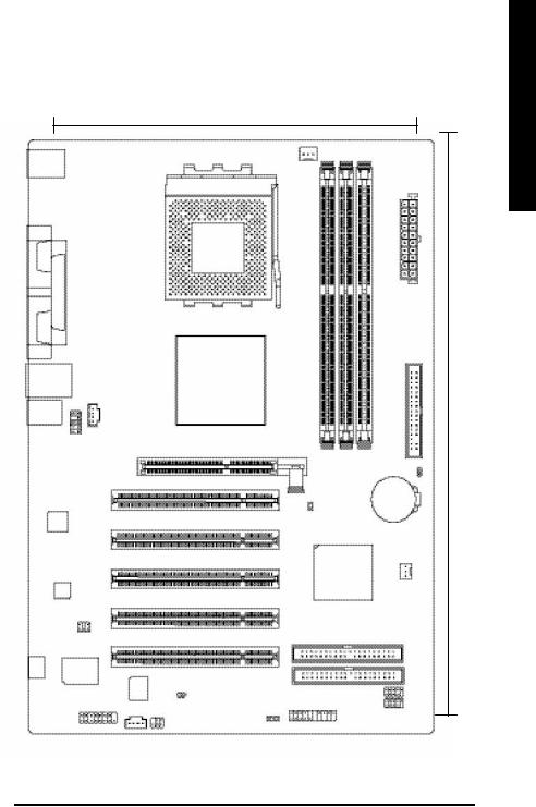
7VT600-RZ Series Motherboard Layout
20.0 cm
KB_MS
COMA |
|
|
|
L P T |
|
COMB |
|
|
USB |
LAN * |
|
AUDIO |
|
|
|
AUDIO |
CD_IN |
|
F_ |
|
V T6103L*
|
CODEC |
|
SUR_CEN |
-C |
I T8 705 |
|
|
|
GAME |
CPU_FAN
|
|
|
|
ATX |
|
SOCKET A |
|
|
|
|
7VT600-RZ |
|
|
FDD |
|
VIA KT600 |
|
|
|
AGP |
DDR1 |
DDR2 |
DDR3 |
|
|
CLR_CMOS |
|||
|
|
|
|
|
|
PCI1 |
|
|
|
|
JP1 |
|
|
BATTERY |
|
|
|
|
|
|
PCI2 |
|
|
|
|
PCI3 |
|
|
|
|
V T8 235 |
|
|
|
|
|
|
|
SYS_FAN |
|
PCI4 |
|
|
|
|
PCI5 |
|
|
|
|
|
|
|
IDE2 |
|
|
|
|
IDE1 |
BIOS |
|
F_U SB1 |
CI |
F_PANEL |
|
AUX_IN |
F_U SB2 |
|
PWR_LED |
|
|
SPDI F_IO |
|
|
|
|
30.5 cm
" * " Support 7VT600-RZ only.
- 7 - |
Introduction |
English
English
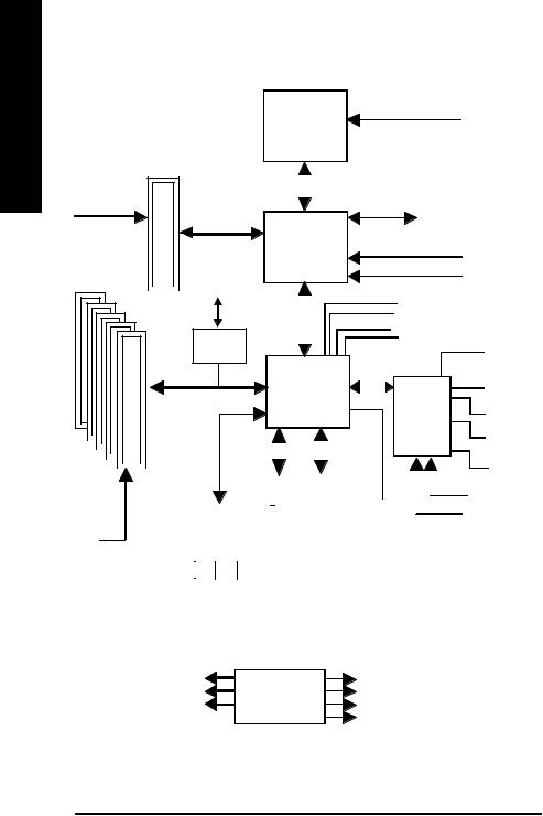
Block Diagram
AGP 4X/8X
AGPCLK (66MHz)
5 PCI |
|
|
|
|
|
|
|
|
|
|
|
RJ45* |
|||
|
|
|
|||||
|
|
|
|||||
|
|
|
|
|
|
|
|
VIA
VT6103L*
|
|
|
|
|
|
|
|
|
|
|
|
|
|
|
|
AC97 Link |
|
|
|
|
|
|
|
|
|
|
|
|
|
|
|
|
|
|
|
|
|
|
|
|
|
|
|
|
|
|
|
|
|
|
|
|
|
|
|
|
|
|
|
|
|
|
|
|
|
|
|
|
|
|
|
|
|
|
|
|
|
|
|
|
|
|
|
|
|
|
|
|
|
|
|
|
|
|
|
|
|
|
|
|
|
|
|
|
|
|
|
|
|
|
|
|
|
|
|
|
|
|
|
|
|
|
|
|
|
|
|
|
|
|
|
|
|
|
|
|
|
|
|
|
|
|
|
|
|
|
|
|
|
|
|
|
|
|
|
|
|
|
|
|
|
|
|
|
|
|
|
|
|
|
|
|
|
|
|
|
|
|
|
|
|
|
|
|
AC97 |
|
|
|
PCICLK |
|
|
CODEC |
|||||||||||
|
|
|
|
|
|
|||||||||||
|
|
(33MHz) |
|
|
|
|
||||||||||
|
|
|
|
|
|
|||||||||||
|
|
|
|
|
|
|
|
|
|
|
|
|
MIC |
LINE-IN |
LINE-OUT |
|
PCICLK (33MHz)
USBCLK (48MHz)
14.318 MHz
33 MHz 

" * " Support 7VT600-RZ only.
7VT600-RZ Series Motherboard
CPUCLK+/- (100/133/166/200MHz)
AMD-K7TM
|
|
|
|
|
|
|
|
|
|
|
|
System Bus100/133/166/200MHz |
|
|
|
|
|
|
|
|
||||||||||||||
|
|
|
|
|
|
|
|
|
|
|
|
|
|
|
|
|
|
|
|
|
|
|
|
|
|
|
|
|
|
|
|
|
|
|
|
|
|
|
|
|
|
|
|
|
|
|
|
|
|
|
|
|
|
|
|
|
|
|
|
|
|
|
|
|
|
|
|
|
|
|
|
|
|
|
|
|
|
|
|
|
VIA |
|
|
|
|
|
|
|
|
|
|
|
DDR RAM |
|
||||||||||
|
|
|
|
|
|
|
|
|
|
|
|
|
|
|
|
|
|
|
|
|
||||||||||||||
|
|
|
|
|
|
|
|
|
|
|
|
|
|
|
|
|
|
|
|
|
|
|
|
|
|
|
|
|
|
|
||||
|
|
|
|
|
|
|
|
|
|
|
|
|
|
|
HCLK+/- (100/133/166/200MHz) |
|||||||||||||||||||
|
|
|
|
|
|
|
|
KT600 |
|
|
|
|
||||||||||||||||||||||
|
|
|
|
|
|
|
|
|
|
|
|
GCLK(66MHz) |
|
|
|
|
|
|
|
|
||||||||||||||
|
|
|
|
|
|
|
|
|
|
|
|
|
|
|
|
|
|
|
|
|
|
|
|
|
|
|
||||||||
|
|
|
|
|
|
Link |
|
|
|
|
|
|
|
|
|
|
|
|
33 MHz |
|
|
|
|
|
|
|
|
|||||||
|
|
|
|
|
|
|
|
|
|
|
|
|
|
|
|
|
|
|
|
|
|
|
||||||||||||
|
|
|
|
|
|
V |
|
|
|
|
|
|
48 MHz |
|
14.318 MHz |
|
|
|
|
|
|
|
|
|||||||||||
|
|
|
|
|
|
66MHz |
|
|
|
|
|
|
|
|
|
|
|
|
|
|
|
|
|
|
|
|||||||||
|
|
|
|
|
|
|
|
|
|
|
|
VCLK(66MHz) |
|
|
|
|
|
|
|
|
||||||||||||||
|
|
|
|
|
|
|
|
|
|
|
|
|
|
BIOS |
||||||||||||||||||||
|
|
|
|
|
|
|
|
|
|
|
VIA |
|
|
|
|
|
|
|
|
|
|
|
|
|
|
|||||||||
|
|
|
|
|
|
|
|
|
|
|
|
|
|
|
|
|
|
|
|
|
|
|
|
|
|
|
|
|
|
|
||||
|
|
|
|
|
|
|
|
|
|
|
|
|
|
|
|
|
|
|
|
|
|
|
|
|
|
|
|
|
|
|
||||
|
|
|
|
|
|
|
|
|
|
|
|
|
|
|
|
|
|
|
|
|
|
|
Game Port |
|||||||||||
|
|
|
|
|
|
|
|
VT8235 |
|
|
|
|
|
|
|
|
|
|
|
|
||||||||||||||
|
|
|
|
|
|
|
|
|
|
|
|
|
|
|
|
|
|
|
|
|
|
|
|
|
|
|
|
|||||||
|
|
|
|
|
|
|
|
|
|
|
|
|
|
|
|
|
|
|
|
|
|
|
|
IT8705 |
|
|
Floppy |
|||||||
|
|
|
|
|
|
|
|
|
|
|
|
|
|
|
|
|
|
|
|
|
|
|
|
|
|
|
|
|
|
|
|
|
||
|
|
|
|
|
|
|
|
|
|
|
|
|
|
|
|
|
|
|
|
|
|
|
|
|
|
24 MHz |
|
|
LPT Port |
|||||
|
|
|
|
|
|
|
|
|
|
|
|
|
|
|
|
|
|
|
|
|
|
|
|
|
|
|
|
|
|
|
|
|
|
|
|
|
|
|
|
|
|
|
|
|
|
|
|
|
|
|
|
|
|
|
|
|
|
|
|
|
|
|
|
|
|
|
|
|
|
|
|
|
|
|
|
|
|
|
|
|
|
|
|
|
|
|
|
|
|
|
|
|
|
|
|
|
|
2 COM |
||||||
|
|
|
|
|
|
|
|
|
|
|
|
|
|
|
|
|
|
|
|
|
|
|
|
|
|
|
|
|||||||
|
|
|
|
|
|
|
|
|
|
|
|
|
|
|
|
|
|
|
|
|
|
|
|
|
33 MHz |
|
|
Ports |
||||||
|
|
|
6 USB |
|
ATA66/100/133 |
|
|
|
|
|
|
|
|
|
|
|
|
|
|
|
||||||||||||||
|
|
|
|
Ports |
|
IDE Channe ls |
|
|
|
|
|
|
|
|
|
|
|
|
|
|
|
|||||||||||||
|
|
|
|
|
|
|
|
|
|
|
|
|
|
|
|
|
|
|
||||||||||||||||
|
|
|
|
PS/2 KB/Mouse |
|
|
|
|
|
|
|
|
||||||||||||||||||||||
|
|
|
|
|
|
|
|
|
|
|
|
|
|
|
|
|
|
|
|
|
|
|
|
|
|
|
|
|||||||
CLK |
|
|
HCLK+/- (100/133/166/200MHz) |
|
|||
|
CPUCLK+/- (100/133/166/200MHz) |
||
GEN |
|
||
|
AGPCLK (66MHz) |
||
|
|||
|
|
|
V_Link (66MHz) / GCLK (66MHz) |
|
|
|
|
- 8 -
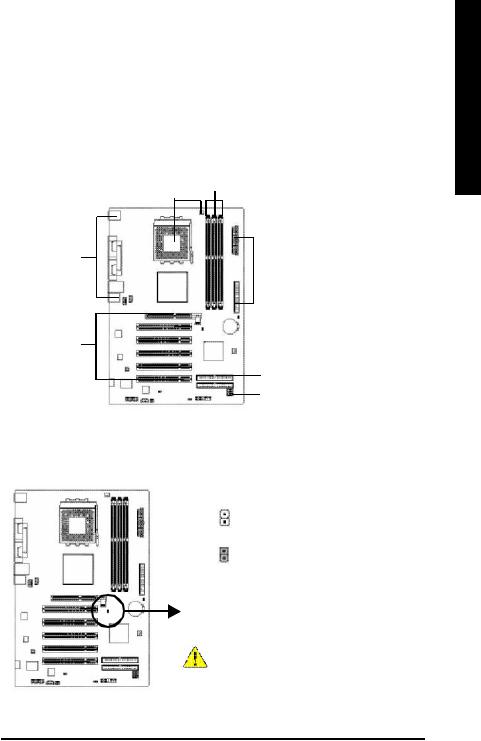
Hardware Installation Process
To set up your computer, you must complete the following steps:
Step 1- Set System Jum per (JP1)
Step 2- Install the Central Processing Unit (CPU)
Step 3- Install memory modules
Step 4- Install expansion cards
Step 5- Install I/O Peripherals cables
Step 2 Step 3
Step 5
 Step 5
 Step 1
Step 4
 Step 5
Step 1: Set System Jumper (JP1)
The system bus frequency can be switched at 100/133/166/200M Hz by adjusting system jumper (JP1). (The internal frequency depend on CPU.)
Open: Auto
1
Close: 100MHz (Defualt)
1
JP1 |
CPU CLOCK |
|
|
|
100MHz |
|
Auto |
|
|
|
|
1-2 |
Close |
|
Open |
|
|
|
|
100MHz : Fix FSB 200M Hz CPU
Auto : Support FSB 266/333/400 MHz CPU
The "JP1" must set to "Auto" when you are using
FSB 266/333/400MHz CPU.
English
- 9 - |
Hardware Installation Process |
English
Step 2: Install the Central Processing Unit (CPU)
Before installing the processor, adhere to the following warning:
1. Please make sure the CPU type is supported by the motherboard.
2. The processor will overheat without the heatsink and/or fan, resulting in permanent
|
irreparable damage. |
3. If you do not match the CPU socket Pin 1 and CPU cut edge well, it will cause |
|
|
improper installation. Please change the insert orientation. |
4. |
Apply therm al grease between the processor and cooling fan. |
5. |
Never run the processor without the heatsink properly and firmly attached. Permanent |
|
dam age will result. |
6. Please set the CPU host frequency in accordance with your processor's specifications. We don't recommend you to set the system bus frequency over the CPU's specification because these specific bus frequencies are not the standard specifications for CPU, chipset and most of the peripherals. Whether your system can run under these specific bus frequencies properly will depend on your hardware configurations, including CPU, Memory, Cards… etc.
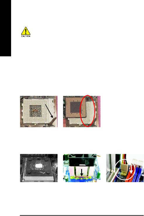
Step 2-1: CPU Installation
Socket ActuationLever
Figure 1.
Pull the rod to the 90-degree directly.
Figure 2.
Locate Pin 1 in the socket and look for a (golden) cut edge on the CPU upper corner. Insert the CPU into
the socket. (Do not force the CPU into the socket.) Then move the socket lever to the locked position while holding pressure on the center of the CPU.
Step 2-2: CPU Cooling Fan Installation
Figure 1.
Apply the thermal tape(or grease) to provide better heat conduction between your CPU and cooling fan.
Figure 2.
Fasten the cooling fan support- ing-base onto the CPU socket on the motherboard.
Figure 3.
Make sure the CPU fan is plugged to the CPU fan connector, than the install completely.
7VT600-RZ Series Motherboard |
- 10 - |
Step 3: Install Memory Modules
Before installing the mem ory modules, adhere to the following warning: 1. When DIMM LED is ON, do not install / remove DIMM from socket.
2. Please note that the DIMM module can only fit in one direction due to the one notch. Wrong orientation will cause improper installation. Please change the insert orientation.
The motherboard has 3 dual inline mem ory module (DIMM) sockets. The BIOS will automatically detects mem ory type and size. To install the mem ory m odule, just push it vertically into the DIMM socket. The DIM M module can only fit in one direction due to the notch. Memory size can vary between sockets.
English
Notch
|
|
DDR |
Support Unbuffered DDR DIMM Sizes type: |
|
|
|
|
|
64 Mbit (2Mx8x4 banks) |
64 Mbit (1Mx16x4 banks) |
128 Mbit(4Mx8x4 banks) |
|
|
|
128Mbit(2Mx16x4 banks) |
256 Mbit(8Mx8x4 banks) |
256Mbit(4Mx16x4 banks) |
|
|
|
512Mbit(16Mx8x4 banks) |
512Mbit(8Mx16x4 banks) |
|
|
|
|
Total System Memory (Max3GB)
1. The DIM M socket has a notch, so the DIM M memory module can only fit in one direction.
2. Insert the DIM M m emory module vertically into the DIMM socket. Then push it down.
3. Close the plastic clip at both edges of the DIMM sockets to lock the DIMM module.
Reverse the installation steps when you wish to remove the DIMM module.
- 11 - |
Hardware Installation Process |
English
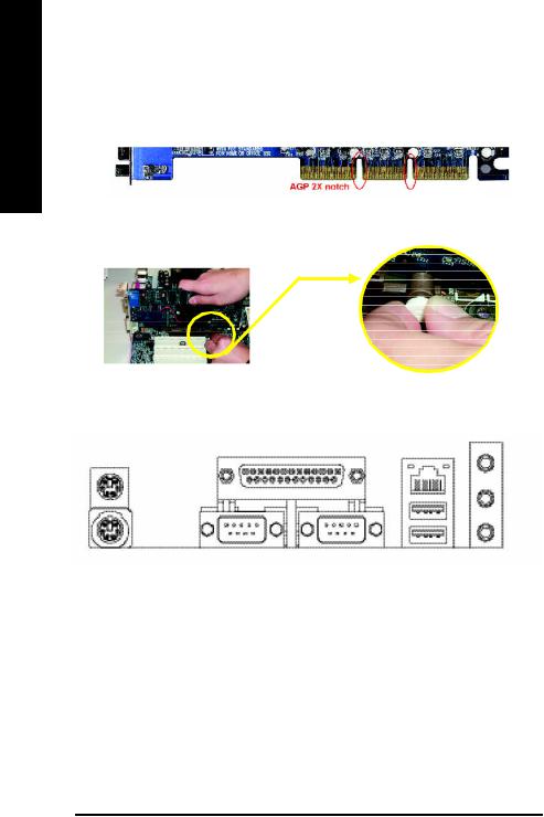
Step 4: Install Expansion Cards
1. Read the related expansion card's instruction document before install the expansion card into the com puter.
2. Please m ake sure your AGP card is AGP 4X/8X (1.5V).
AGP 4X /8X notch
3. Please carefully pull out the small whitedrawable bar at the end of the AGP slot when you try to install/ Uninstall the AGP card. Please align the AGP card to the onboard AGP slot and press firmly down on the slot .M ake sure your AGP card is locked by the sm all whitedrawable bar.
AGP Card
Step 5: Install I/O Peripherals Cables
Step 5-1: I/O Back Panel Introduction
v |
|
y |
u |
|
{ |
w |
x z |
| |
|
|
} |
uPS/2 Keyboard and PS/2 Mouse connector
This connector supports standard PS/2 keyboard and PS/2 mouse.
vParallel port (LPT)
Device like printer can be connected to Parallel port.
w/x Serial ports (COMA / COMB)
Mouse and modem etc. can be connected to Serial port.
yLAN port *
LAN is fast Ethernet with 10/100Mbps speed.
zUSB port
Before you connect your device(s) into USB connector(s), please make sure your device(s) such as USB keyboard, mouse, scanner, zip, speaker...etc. Have a standard USB interface. Also make sure your OS supports USB controller. If your OS does not support USB controller, please contact OS vendor for possible patch or driver upgrade. For more information please contact your OS or device(s) vendors.
" * " Support 7VT600-RZ only. |
|
7VT600-RZ Series Motherboard |
- 12 - |
 Loading...