


Interlogix UVP-RE4-D27P, UVP-RE4-D37P, UVP-RE8-D27P, UVP-RE8-D37P, UVP-R4-D37P Installation
...UltraView PTZ
Installation Manual
Copyright
Disclaimer
Trademarks and
patents
Software license agreement
Copyright © 2011 UTC Fire & Security. All rights reserved.
This document may not be copied or otherwise reproduced, in whole or in part, except as specifically permitted under US and international copyright law, without the prior written consent from UTC Fire & Security.
Document number: 1069678B-EN (February 2011)
THE INFORMATION IN THIS DOCUMENT IS SUBJECT TO CHANGE WITHOUT NOTICE. UTC FIRE AND SECURITY ASSUMES NO RESPONSIBILITY FOR INACCURACIES OR OMISSIONS AND SPECIFICALLY DISCLAIMS ANY LIABILITIES, LOSSES, OR RISKS, PERSONAL OR OTHERWISE, INCURRED AS A CONSEQUENCE, DIRECTLY OR INDIRECTLY, OF THE USE OR APPLICATION OF ANY OF THE CONTENTS OF THIS DOCUMENT. FOR THE LATEST DOCUMENTATION, CONTACT YOUR LOCAL SUPPLIER OR VISIT US ONLINE AT WWW.INTERLOGIX.COM.
This publication may contain examples of screen captures and reports used in daily operations. Examples may include fictitious names of individuals and companies. Any similarity to names and addresses of actual businesses or persons is entirely coincidental.
UltraView name and logo are trademarks of UTC Fire & Security. Interlogix is a trademark of UTC Fire & Security.
UltraView PTZ is a trademark of UTC Fire & Security.
Other trade names used in this document may be trademarks or registered trademarks of the manufacturers or vendors of the respective products.
IImportant: This end-user license agreement (“Agreement”) is a legal agreement between UTC Fire & Security and You. Read the following terms and conditions carefully before installing or using this Software. This agreement provides a license from UTC Fire & Security to use the Software. It also contains warranty information, disclaimers, and liability limitations. Installing and/or using the Software confirms Your agreement to be bound by these terms and conditions. If You do not agree with these terms and conditions, do not install or use the Software or, if already installed, immediately cease all use of the Software and promptly uninstall all components of the Software.
Definitions. The following definitions apply to this document:
a.“UTC Fire & Security”, with respect to title to or warranty of the Software, means UTC Fire & Security Americas Corporation, Inc.
b.“Software” means SymNav, the executable software or firmware programs and accompanying documentation installed on the Interlogix products, plus any upgrades, modified versions, updates, additions, and copies of the software furnished to Customer during the term of the license granted herein.
c.“Documentation” means all associated media, printed materials, and electronic documentation accompanying the Software.
d.“Licensed Product” means the Software and Documentation.
e.“Customer” means the person or organization, or parent or subsidiary thereof, who uses the Software for its intended purposes, and excludes distributors, authorized resellers, value-added resellers and original equipment manufacturers. Customer may be referred to as You or Your, whether an individual or a business entity of any kind.
f.“Machine” means the computer, workstation, terminal, or other hardware product on which the Software is installed.
License. All rights to and in the Licensed Product, including, but not limited to, copyrights, patents, trademarks, and trade secrets, belong to UTC Fire & Security, and UTC Fire & Security retains title to each copy of the Software. You agree that UTC Fire & Security at any time, upon reasonable notice, may audit Your use of the Software for compliance with the terms and conditions of this Agreement. Subject to the terms and conditions of this Agreement, UTC Fire & Security grants You a nonexclusive license to use the Software, but only in the country where acquired, provided that You agree to the following:

iii
You may:
g.install and use the Software on a single Machine at one time, unless You have purchased additional copies of the Software, in which case You may install the software on the number of Machines for which You have purchased copies of the Software;
h.use the original copy of the Software provided to You for backup purposes.
You may not:
a.transfer or distribute the Licensed Product to others, in electronic format or otherwise, and this Agreement shall automatically terminate in the event of such a transfer or distribution;
b.use the Software over a computer network;
c.sell, rent, lease, or sublicense the Software;
d.copy or modify the Licensed Product for any purpose, including for backup purposes.
Term. This Agreement is effective until terminated. You may terminate this Agreement by uninstalling all components of the Software from all Machines and returning the Software to UTC Fire & Security. UTC Fire & Security may terminate this Agreement if You breach any of these terms and conditions. Upon termination of this Agreement for any reason, You agree to uninstall all components of the Software and return the Licensed Product to UTC Fire & Security. All provisions of this Agreement relating to (i) disclaimer of warranties; (ii) limitations on liability, remedies, and damages; and (iii) UTC Fire & Security’s proprietary rights, shall survive termination of this Agreement.
Object code. The Software is delivered in object code only. You may not alter, merge, modify, adapt, or translate the Software, nor decompile, disassemble, reverse-engineer, or otherwise reduce the Software to a human-perceivable form, nor create derivative works or programs based on the Software.
Limited warranty. UTC Fire & Security warrants that for one (1) year from the date of delivery of the Licensed Product (Software Warranty Period), the functions contained in the Software will be fit for their intended purpose as described in the applicable Documentation from UTC Fire & Security, and will conform in all material respects to the specifications stated in such Documentation. UTC Fire & Security does not warrant that the operation of the Software will be uninterrupted or error-free. UTC Fire & Security does warrant that the media on which the Software is furnished will be free from defects in materials and workmanship under normal use for a period of thirty (30) days from the date of delivery (Media Warranty Period). Except as specifically provided therein, any other software and any hardware furnished with or accompanying the Software is not warranted by UTC Fire & Security.
Your exclusive remedy under this limited warranty for nonconforming Software shall be repair or replacement of the Software, at the sole discretion of UTC Fire & Security. To obtain a repair or replacement of nonconforming Software, contact UTC Fire & Security Customer Service toll-free at 888-437-3287 or online at www.interlogix.com during the Software Warranty Period.
Except as expressly provided above, the licensed product is provided “as is” without warranty of any kind, either expressed or implied, including, but not limited to, implied warranties of merchantability or fitness for a particular purpose and, except as expressly provided above, You assume the entire risk as to the quality and performance of the licensed product.
Limitation of liability. UTC Fire & Security’s sole obligation or liability under this agreement is the repair or replacement of nonconforming software and/or defective media according to the limited warranty above. In no event will UTC Fire & Security be liable for damages, whether consequential, incidental, or indirect, nor for loss of data, loss of profits, or lost savings, arising from use or inability to use the software or documentation (or any hardware furnished with the software), even if UTC Fire & Security has been advised of the possibility of such damages, nor for any claim by any third party.

iv  UltraView PTZ Installation Manual
General. Any materials provided to You by UTC Fire & Security shall not be exported or reexported in violation of any export provisions of the USA or any other applicable jurisdiction. Any attempt to sublicense, assign, or transfer any of the rights, duties, or obligations hereunder shall be void. This Agreement shall be governed by and interpreted under the laws of the State of New York, United States of America, without regard to conflicts of law provisions. You hereby consent to the exclusive jurisdiction of the state and federal courts located in Multnomah County, Oregon, to resolve any disputes arising under or in connection with this Agreement, with venue in Portland, Oregon.
Restricted rights legend. The Licensed Product is provided with RESTRICTED RIGHTS. In the event the United States Government or an agency thereof is granted a license, the following additional terms apply: Restricted Computer Software, as defined in the Commercial Computer Software–Restricted Rights clause at Federal Acquisition Regulations 52.227-19, and the restrictions as provided in subparagraphs (c)(1) and (c)(2) thereof; and as applicable, the Government’s rights to use, modify, reproduce, release, perform, display, or disclose the Software also are restricted as provided by paragraphs (b)(2) and (b)(3) of the Rights in Noncommercial Technical Data and Computer Software–Small Business Innovative Research (SBIR) Program clause at DFARS 252.227-7018.
Acknowledgment. You acknowledge that You have read and understand this agreement and agree to be bound by its terms. You further agree that this agreement is the complete and exclusive statement of the agreement between You and UTC Fire & Security, and supersedes any proposal or prior agreement, oral or written, and any other communication relating to the subject matter of this agreement.
Intended use Use this product only for the purpose it was designed for; refer to the data sheet and user documentation. For the latest product information, contact your local supplier or visit us online at www.interlogix.com.
Manufacturer UTC Fire & Security Americas Corporation, Inc. 2955 Red Hill Ave, Costa Mesa, CA 92626, USA
Certification
FCC compliance
ACMA compliance
N4131
This equipment has been tested and found to comply with the limits for a Class A digital device, pursuant to part 15 of the FCC Rules. These limits are designed to provide reasonable protection against harmful interference when the equipment is operated in a commercial environment. This equipment generates, uses, and can radiate radio frequency energy and, if not installed and used in accordance with the instruction manual, may cause harmful interference to radio communications.
Changes or modifications not expressly approved by the party responsible for compliance could void the user’s authority to operate the equipment.
Notice! This is a Class A product. In a domestic environment this product may cause radio interference in which case the user may be required to take adequate measures.
Canada This Class A digital apparatus complies with Canadian ICES-003.
Cet appareil numérique de la classe A est conforme à la norme NMB-003 du Canada.
EU Directives 2004/108/EC (EMC Directive). Non-European manufacturers must designate an authorized representative in the Community. Our authorized manufacturing representative is UTC Fire & Security, Kelvinstraat 7, 6003 DH Weert, Nederland.
2004/108/EC (EMC Directive): Hereby, UTC Fire & Security declares that this device is in compliance with the essential requirements and other relevant provisions of Directive 2004/ 108/EC.

v
2002/96/EC (WEEE directive). Products marked with this symbol cannot be disposed of
as unsorted municipal waste in the European Union. For proper recycling, return this
product to your local supplier upon the purchase of equivalent new equipment, or dispose of it at designated collection points. For more information, visit www.recyclethis.info.
Contact information For contact information, see www.interlogix.com.

vi  UltraView PTZ Installation Manual

vii
Contents
Preface. . . . . . . . . . . . . . . . . . . . . . . . . . . . . . . . . . . . . . . . . . . . . . . . . . . . . . . . . . . . . . . . . . ix
Conventions used in this document. . . . . . . . . . . . . . . . . . . . . . . . . . . . . . . . . . . . . . . . . . . . . ix Safety terms and symbols . . . . . . . . . . . . . . . . . . . . . . . . . . . . . . . . . . . . . . . . . . . . . . . . . . . . . ix
Chapter 1. Introduction . . . . . . . . . . . . . . . . . . . . . . . . . . . . . . . . . . . . . . . . . . . . . . . . . . 1
Product overview . . . . . . . . . . . . . . . . . . . . . . . . . . . . . . . . . . . . . . . . . . . . . . . . . . . . . . . . . . 2
Product contents . . . . . . . . . . . . . . . . . . . . . . . . . . . . . . . . . . . . . . . . . . . . . . . . . . . . . . . . . . . . . 2
System requirements . . . . . . . . . . . . . . . . . . . . . . . . . . . . . . . . . . . . . . . . . . . . . . . . . . . . . . . 3
Operational requirements . . . . . . . . . . . . . . . . . . . . . . . . . . . . . . . . . . . . . . . . . . . . . . . . . . . . . . 3 Minimum load requirements . . . . . . . . . . . . . . . . . . . . . . . . . . . . . . . . . . . . . . . . . . . . . . . . . . . . 4 Power requirements . . . . . . . . . . . . . . . . . . . . . . . . . . . . . . . . . . . . . . . . . . . . . . . . . . . . . . . . . . . 5 Cable management. . . . . . . . . . . . . . . . . . . . . . . . . . . . . . . . . . . . . . . . . . . . . . . . . . . . . . . . . . . . 5 Cable requirements . . . . . . . . . . . . . . . . . . . . . . . . . . . . . . . . . . . . . . . . . . . . . . . . . . . . . . . . . . . 6 Power cable size and length requirements . . . . . . . . . . . . . . . . . . . . . . . . . . . . . . . . . . . . . . . . 7
Chapter 2. Housings and cables . . . . . . . . . . . . . . . . . . . . . . . . . . . . . . . . . . . . . . . . . . 9
Backward compatibility with CyberDome I housings . . . . . . . . . . . . . . . . . . . . . . . . . . . . 10 Various mounting and housing styles . . . . . . . . . . . . . . . . . . . . . . . . . . . . . . . . . . . . . . . . 10 Wiring best practices . . . . . . . . . . . . . . . . . . . . . . . . . . . . . . . . . . . . . . . . . . . . . . . . . . . . . . 12
Pendant-mount wire routing . . . . . . . . . . . . . . . . . . . . . . . . . . . . . . . . . . . . . . . . . . . . . . . . . . . 12 Flush-mount wire routing . . . . . . . . . . . . . . . . . . . . . . . . . . . . . . . . . . . . . . . . . . . . . . . . . . . . . 13
Pendant-mount housings . . . . . . . . . . . . . . . . . . . . . . . . . . . . . . . . . . . . . . . . . . . . . . . . . . 14
Preparing the surface for pendant-mounts . . . . . . . . . . . . . . . . . . . . . . . . . . . . . . . . . . . . . . . 14 Installing the housing . . . . . . . . . . . . . . . . . . . . . . . . . . . . . . . . . . . . . . . . . . . . . . . . . . . . . . . . 14
Flush-mount housings. . . . . . . . . . . . . . . . . . . . . . . . . . . . . . . . . . . . . . . . . . . . . . . . . . . . . 16
Preparing the surface for flush-mounts . . . . . . . . . . . . . . . . . . . . . . . . . . . . . . . . . . . . . . . . . . 16 Installing the housing . . . . . . . . . . . . . . . . . . . . . . . . . . . . . . . . . . . . . . . . . . . . . . . . . . . . . . . . 17
Fan installation . . . . . . . . . . . . . . . . . . . . . . . . . . . . . . . . . . . . . . . . . . . . . . . . . . . . . . . . . . . 19 Preparing the cables . . . . . . . . . . . . . . . . . . . . . . . . . . . . . . . . . . . . . . . . . . . . . . . . . . . . . . 20
Chapter 3. Wiring. . . . . . . . . . . . . . . . . . . . . . . . . . . . . . . . . . . . . . . . . . . . . . . . . . . . . . 21
Components used for basic and advanced operation . . . . . . . . . . . . . . . . . . . . . . . . . . . 22
Alarm/contact connectors . . . . . . . . . . . . . . . . . . . . . . . . . . . . . . . . . . . . . . . . . . . . . . . . . . . . . 23
Wiring the housing board . . . . . . . . . . . . . . . . . . . . . . . . . . . . . . . . . . . . . . . . . . . . . . . . . . 24 Setting the termination . . . . . . . . . . . . . . . . . . . . . . . . . . . . . . . . . . . . . . . . . . . . . . . . . . . . 26

viii  UltraView PTZ Installation Manual
Chapter 4. Camera assembly, shroud, bubble dome. . . . . . . . . . . . . . . . . . . . . . . . . 27
Camera assembly preparation and installation. . . . . . . . . . . . . . . . . . . . . . . . . . . . . . . . . 28
Setting the protocol . . . . . . . . . . . . . . . . . . . . . . . . . . . . . . . . . . . . . . . . . . . . . . . . . . . . . . . . . . 29 Setting the camera’s address . . . . . . . . . . . . . . . . . . . . . . . . . . . . . . . . . . . . . . . . . . . . . . . . . . 30 Installing the camera assembly . . . . . . . . . . . . . . . . . . . . . . . . . . . . . . . . . . . . . . . . . . . . . . . . 32
Shroud and bubble dome installation . . . . . . . . . . . . . . . . . . . . . . . . . . . . . . . . . . . . . . . . 32
Installing a camera shroud . . . . . . . . . . . . . . . . . . . . . . . . . . . . . . . . . . . . . . . . . . . . . . . . . . . . 33 Installing a bubble dome . . . . . . . . . . . . . . . . . . . . . . . . . . . . . . . . . . . . . . . . . . . . . . . . . . . . . . 34
Chapter 5. Troubleshooting, maintenance, support . . . . . . . . . . . . . . . . . . . . . . . . . 37
Troubleshooting . . . . . . . . . . . . . . . . . . . . . . . . . . . . . . . . . . . . . . . . . . . . . . . . . . . . . . . . . . 38 Maintenance . . . . . . . . . . . . . . . . . . . . . . . . . . . . . . . . . . . . . . . . . . . . . . . . . . . . . . . . . . . . . 39
Cleaning the bubble dome. . . . . . . . . . . . . . . . . . . . . . . . . . . . . . . . . . . . . . . . . . . . . . . . . . . . . 39
Contacting us . . . . . . . . . . . . . . . . . . . . . . . . . . . . . . . . . . . . . . . . . . . . . . . . . . . . . . . . . . . . 40
Online . . . . . . . . . . . . . . . . . . . . . . . . . . . . . . . . . . . . . . . . . . . . . . . . . . . . . . . . . . . . . . . . . . . . . 40
. . . . . . . . . . . . . . . . . . . . . . . . . . . . . . . . . . . . . . . . . . . . . . . . . . . . . . . . . . . . . . . . . . . . . . . . . . . 40
GEA-102 wall-mount arm . . . . . . . . . . . . . . . . . . . . . . . . . . . . . . . . . . . . . . . . . . . . . . . . . . . 42
Installing the wall-mount arm . . . . . . . . . . . . . . . . . . . . . . . . . . . . . . . . . . . . . . . . . . . . . . . . . . 42 Opening a conduit hole . . . . . . . . . . . . . . . . . . . . . . . . . . . . . . . . . . . . . . . . . . . . . . . . . . . . . . . 45
GEA-114 T-bar ceiling support kit. . . . . . . . . . . . . . . . . . . . . . . . . . . . . . . . . . . . . . . . . . . . 47
Installing the T-bar ceiling support kit . . . . . . . . . . . . . . . . . . . . . . . . . . . . . . . . . . . . . . . . . . . 47
UltraView PTZ protocol functionality . . . . . . . . . . . . . . . . . . . . . . . . . . . . . . . . . . . . . . . . . 52 Equipment protocol testing list. . . . . . . . . . . . . . . . . . . . . . . . . . . . . . . . . . . . . . . . . . . . . . 56

ix
Preface
This is the Interlogix UltraView PTZ Installation Manual. This document includes an overview of the product and detailed instructions explaining:
•how to install the housing; and
•how to attach the pan/tilt/zoom (PTZ) camera assembly.
There is also information describing how to contact technical support if you have questions or concerns. To use this document effectively, you should have the following minimum qualifications:
•a basic knowledge of CCTV systems and components; and
•a basic knowledge of electrical wiring and low-voltage electrical connections.
Read these instructions and all ancillary documentation entirely before installing or operating this product. The most current versions of this and related documentation may be found on our website at www.interlogix.com.
Note: A qualified service person, complying with all applicable codes, should perform all required hardware installation.
Conventions used in this document
The following conventions are used in this document:
Bold |
Menu items and buttons. |
|
|
Italic |
Emphasis of an instruction or point; special terms. |
|
|
|
File names, path names, windows, panes, tabs, fields, variables, and other GUI elements. |
|
|
|
Titles of books and various documents. |
|
|
Blue italic |
(Electronic version.) Hyperlinks to cross-references, related topics, and URL addresses. |
|
|
Monospace |
Text that displays on the computer screen. |
|
Programming or coding sequences. |
|
|
Safety terms and symbols
These terms may appear in this manual:
CAUTION: Cautions identify conditions or practices that may result in damage to the equipment or other property.
WARNING: Warnings identify conditions or practices that could result in equipment damage or serious personal injury.

x  UltraView PTZ
Installation Manual
Chapter 1 Introduction
This chapter provides an overview of your UltraView PTZ dome system, including product contents and system requirements.
In this chapter:
Product overview . . . . . . . . . . . . . . . . . . . . . . . . . . . . . . . . . . . . . . . . . . . .2 Product contents . . . . . . . . . . . . . . . . . . . . . . . . . . . . . . . . . . . . . . . . .2 System requirements . . . . . . . . . . . . . . . . . . . . . . . . . . . . . . . . . . . . . . . . .3 Operational requirements . . . . . . . . . . . . . . . . . . . . . . . . . . . . . . . . . .3 Minimum load requirements . . . . . . . . . . . . . . . . . . . . . . . . . . . . . . . .4 Cable management . . . . . . . . . . . . . . . . . . . . . . . . . . . . . . . . . . . . . . .5 Cable requirements . . . . . . . . . . . . . . . . . . . . . . . . . . . . . . . . . . . . . . .6
Power cable size and length requirements . . . . . . . . . . . . . . . . . . . . .7

2  UltraView PTZ
Installation Manual
Product overview
UltraView PTZ ™ is a line of advanced pan/tilt/zoom (PTZ) cameras. In addition to powerful cameras, UltraView PTZ features a graphical programming interface for easier customization of camera settings, and passcodes for protection against unauthorized access.
The UltraView PTZ supports many protocols to work with various keypad controllers, digital video recorders, and other video surveillance equipment. (See Setting the protocol on page 27 for a list of supported protocols.)
Installation of the UltraView PTZ line of domes is simplified because all power, data, video, and alarm connections are provided in the housing. Configuration parameters such as presets and tours unique to each installation site are stored in the housing memory. This allows you to replace cameras or move them between housings without having to reprogram them for each new site. As you install the first dome, you will find many other enhancements that make installation easier and quicker.
The general steps for installing your dome include:
•preparing the mounting surface and installing the mount (if used) and housing;
•preparing the cables and wiring the housing;
•addressing the camera site, setting the protocol, and setting the termination;
•installing the PTZ camera assembly; and
•installing the dome.
Be aware that the power requirements for CyberDome and UltraView PTZ are different. See Power requirements on page 5 and Cable management on page 5.
Product contents
The UltraView PTZ consists of the following:
•Housing.
•Package containing three connectors (one 2-pin for power; one 6-pin for UTP, auxiliary data, and RS-485; one 14-pin for alarms and contacts) and a small screwdriver. (The Select version of UltraView PTZ has two connectors: a 2-pin connector for power and a 2-pin connector for RS-485 data.)
•PTZ camera assembly.
•Dome (mirror domes are shipped with cotton gloves for special handling).
•Mount (wall-mount and flush-mount versions only).
•Installation and user manuals.
You may receive the package contents in one large carton containing three boxes (four with wall-mount versions), or if shipped individually, you may receive three (or four) separate boxes. One box will contain the housing, connectors, and manuals. The PTZ assembly, dome, and mount (for wall-mount versions) are each shipped in separate boxes.
Inspect the packages and contents for visible damage. If any components are damaged or missing, do not use the unit; contact the supplier immediately. If you need to return the unit, you must ship it in the original box.

Chapter 1  3
3
Introduction
System requirements
For proper operation, adhere to the following operational, load, cable, and power requirements for UltraView PTZ domes.
Operational requirements
UltraView PTZ contains a built-in receiver that decodes commands originating from a compatible controlling device, such as a keypad or ASCII control software. A minimum of one controlling device is required for operation, as shown in Figure 1. In this typical DVR system, an operator can pan, tilt, and zoom the camera, find presets, and start preset and ShadowTours from the keypad.
Figure 1. Typical DVR system
|
|
|
|
|
|
|
UltraView PTZ |
|
|
|
|
|
|
|
|
||
|
|
|
|
|
|
|
||
|
|
|
|
|
|
|
||
|
|
|
|
|
|
|
||
|
|
|
|
|
|
|
||
|
|
|
|
|
|
|
||
CCTV |
|
|
SymDec 16 DVR |
I/O box |
KTD-405A |
|||
monitor |
|
(IP digital video recorder) |
|
controller keypad |
|
|
||
|
|
|
|
|
|
|
|
RS-485 |
|
|
|
|
|
|
|
|
Video |
|
|
|
|
|
|
|
|
|
Figure 2 shows a typical network system, and Figure 3 on page 4 shows an enhanced system.
Figure 2. Typical IP system
UltraView PTZ
RS-485
TCP/IP
Video
SymNet |
I/O box |
KTD-405A |
CCTV |
IP encoder/decoders |
|
controller keypad |
monitor |
4  UltraView PTZ
Installation Manual
Figure 3. Typical enhanced system
CCTV
KTD-440 switcher
Alarm inputs |
Relay |
(dry contacts) |
outputs |
SymDec 16 DVR
UltraView PTZ
Example site ID #15
|
|
|
|
|
RS-422 |
|
|
|
|
|
RS-485 |
I/O box |
KTD-405A |
I/O box |
KTD-405A |
KTD-83 data |
Video |
|
controller keypad |
|
controller keypad |
distributor |
Alarms/ |
|
|
|
|
|
Outputs
Minimum load requirements
Table 1 lists the load requirements for all UltraView PTZ dome configurations.
Table 1. Minimum load requirements of dome configurations
Dome configuration |
Minimum load |
|
|
Rugged, cast aluminum pendant-mount housing (with any mount) |
100 lb. (45.3 kg) |
|
|
Heavy-duty housing (with any mount) |
|
|
|
Swing-arm mount (with any dome except heavy duty or flush-mount) |
|
|
|
All other dome and mount configurations |
50 lb. (22.7 kg) |
|
|
|
|
CAUTION: For safety, the mounting surface, hardware, and procedure used for securing the dome must support the weight of the dome, mount (if used), cables, and any structural or environmental vibration according
to local codes.

Chapter 1  5
5
Introduction
Power requirements
Every UltraView PTZ dome requires a 24 VAC power supply to operate the PTZ, camera, and heater/fan, if present. The startup and running power requirements vary depending on the model (Table 2).
Table 2. Power requirements at 24 VAC (±4 VAC) operating voltage
Model |
Startup |
Running |
Minimum power source |
power |
power |
to use |
|
|
|
|
|
Dome with fan |
30 VA |
25 VA |
40 VA |
|
|
|
|
Dome with 12 W heater/fan (×2) |
93 VA |
35 to 55 VA |
56 VA |
|
|
|
|
Rugged and HD dome with 23 W heater/fan (×2) |
153 VA |
75 VA |
100 VA |
|
|
|
|
|
|
|
|
CAUTION: Use only a Class 2 power supply of the required output rating as listed on individual units and specified.
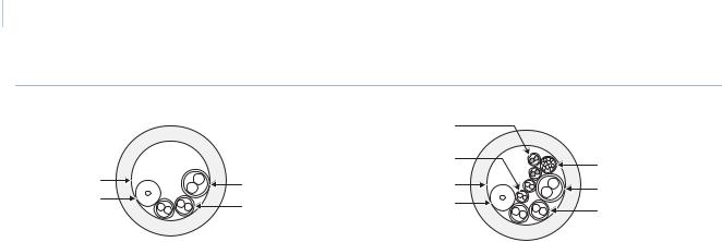
Cable management
Follow all local codes for cable management. As a general rule, you can fill a cable conduit to a maximum of 60% of its capacity. You must maintain 40% free space. A variety of factors will determine how many cables you can run into the dome. Capacity limitations include:
•number of cables
•size of the cables
•use of single-conductor or multiple-conductor cable
•use of a junction box
Figure 4 provides an illustration of the cable capacity of three typical applications. It is important to note that all cables of the same gauge are not of the same diameter. Manufacturer, shielding, and rating affect the actual diameter of cables of the same gauge. Interlogix leaves the selection of the appropriate cable to the discretion of the installer who is working with the local codes of the installation site.
6  UltraView PTZ
Installation Manual
Figure 4. Three acceptable typical cabling scenarios
Video (UTP)
|
|
(two) |
Alarms |
|
|
Relays (two) |
|
|
|
(multiconnector) |
|
|
|
|
|
3/4 in. dia. |
Power |
3/4 in. dia. |
Power |
Video |
Data |
Video |
Data |
|
|
||
|
(two, daisy-chained) |
|
(two, daisy- |
Percentage conduit fill = 38%, includes:
•Video: one 59U/6U coaxial (0.24 in. dia)
•Data: two 20 AWG UTP (0.19 in. dia)
•Power: one 16 AWG UTP (0.25 in. dia)
Percentage conduit fill = 53%, includes:
•Video: one 59U/6U coaxial (0.24 in.dia)
•Data: two 20 AWG UTP (0.19 in. dia)
•Power: one 16 AWG UTP (0.25 in. dia)
•Alarms: 24 AWG UTP (0.11 in. dia.)
•Relays: 24 AWG UTP (0.11 in. dia.)
•Video UTP: 24 AWG UTP (0.11 in. dia.)
Cable requirements
Table 3 lists the requirements for the cables that connect to the dome.
Table 3. Cable requirements
|
|
Length |
|
Operation |
Cable requirement |
|
|
feet |
meters |
||
Data |
For RS-422: 22 gauge (0.64 mm) unshielded, two-conductor, twisted-pair (UTP) |
10,000 |
3,000 |
|
cable |
|
|
|
|
|
|
|
For RS-485: 22 gauge (0.64 mm) shielded, two-conductor, twisted-pair (STP) |
3,000 |
900 |
|
cable |
|
|
|
|
|
|
Video |
75 ohm coaxial cable (RG59 with lift/gain) |
1,600 |
486 |
|
|
|
|
|
22 gauge (0.64 mm) unshielded, two-conductor, twisted-pair (UTP) cable |
1,250 |
381 |
|
Note: Use only crimp-on BNC connectors. Do not use screw-on connectors. |
|
|
|
|
|
|
Alarm |
Cat-5 cable (recommended) |
1,250 |
381 |
|
|
|
|
Relay contacts |
Cat-5 cable (recommended). Contacts rated for 60 W DC, 62.5 W AC with 2 A |
1,250 |
381 |
|
max. |
|
|
|
|
|
|
Power |
24 VAC. To determine the size of cable needed for individual applications, see Power cable size and |
||
|
length requirements. |
|
|
|
|
|
|
Note: When using UTP cable for video and data, the wires can share the same jacket but must remain separate twisted pairs.

Chapter 1  7
7
Introduction
Power cable size and length requirements
Using the proper gauge of power cable will ensure proper operation and avoid voltage drops. See Table 4 for the recommended cable gauge for varying maximum cable lengths and power draws.
Table 4. Recommended power cable gauges based on maximum lengths for an operating voltage of 24 VAC (±4 VAC)
Wire gauge |
Domes with fan (20 VA) |
|
Domes with |
HD domes with |
||||
12 W heater/fan (x2) (45 VA) |
23 W heater/fan (x2) (66 VA) |
|||||||
|
|
|
|
|
|
|
|
|
|
mm |
|
|
|
|
|
|
|
AWG |
(dia.) |
feet |
meters |
feet |
|
meters |
feet |
meters |
10 |
2.60 |
1569 |
478 |
784 |
|
238 |
490 |
149 |
|
|
|
|
|
|
|
|
|
12 |
2.05 |
988 |
301 |
494 |
|
150 |
309 |
94 |
|
|
|
|
|
|
|
|
|
14 |
1.62 |
620 |
188 |
310 |
|
94 |
194 |
59 |
|
|
|
|
|
|
|
|
|
16 |
1.29 |
391 |
119 |
196 |
|
59 |
122 |
37 |
|
|
|
|
|
|
|
|
|
18 |
1.02 |
246 |
74 |
123 |
|
37 |
77 |
23 |
|
|
|
|
|
|
|
|
|
|
|
|
|
|
|
|
|
|
WARNING: Be aware that the power requirements for UltraView PTZ are different, which may require new cabling when replacing CyberDomes with UltraView PTZ domes.

8  UltraView PTZ
Installation Manual

Chapter 2 Housings and cables
This chapter provides instructions for installing housings and cables.
In this chapter:
Backward compatibility with CyberDome I housings . . . . . . . . . . . . . . .10
Various mounting and housing styles . . . . . . . . . . . . . . . . . . . . . . . . . . .10
Wiring best practices . . . . . . . . . . . . . . . . . . . . . . . . . . . . . . . . . . . . . . . .12
Pendant-mount wire routing . . . . . . . . . . . . . . . . . . . . . . . . . . . . . . .12
Flush-mount wire routing . . . . . . . . . . . . . . . . . . . . . . . . . . . . . . . . .13
Pendant-mount housings . . . . . . . . . . . . . . . . . . . . . . . . . . . . . . . . . . . . .14
Preparing the surface for pendant-mounts . . . . . . . . . . . . . . . . . . . .14
Installing the housing . . . . . . . . . . . . . . . . . . . . . . . . . . . . . . . . . . . .14
Flush-mount housings . . . . . . . . . . . . . . . . . . . . . . . . . . . . . . . . . . . . . . .16
Preparing the surface for flush-mounts . . . . . . . . . . . . . . . . . . . . . .16
Installing the housing . . . . . . . . . . . . . . . . . . . . . . . . . . . . . . . . . . . .17
Fan installation . . . . . . . . . . . . . . . . . . . . . . . . . . . . . . . . . . . . . . . . . . . .19
Preparing the cables . . . . . . . . . . . . . . . . . . . . . . . . . . . . . . . . . . . . . . . .20
10  UltraView PTZ
Installation Manual
Backward compatibility with CyberDome I housings
The UltraView PTZ is compatible with CyberDome I housings, but there are some exceptions. Although the onscreen display (OSD) interface, including menus, will show the UltraView PTZ design, not all of the UltraView PTZ features are supported on CyberDome I housings. The following features are not available:
•Site-tied memory
•Internal alarms
•Internal relays
•Internal wiring terminal blocks
•Advanced heater and fan system
•Lift and gain functionality.
•Up-the-coax (UTC) protocol support
Also, if you install an UltraView PTZ in an older CyberDome I housing, you must install a fan assembly on the tilt arm of the PTZ. (See Fan installation on page 19 for instructions.) You may use the fan from your CyberDome I PTZ, or call Customer Service (see Contacting us on page 38) to order a new one (part number 1046540).
WARNING: UltraView PTZ has different power requirements to those of the CyberDome I. Consequently new cabling may be required when replacing CyberDomes with UltraView PTZ domes.. Ensure that the correct power cable is used. See Table 4 on page 6 for further information.
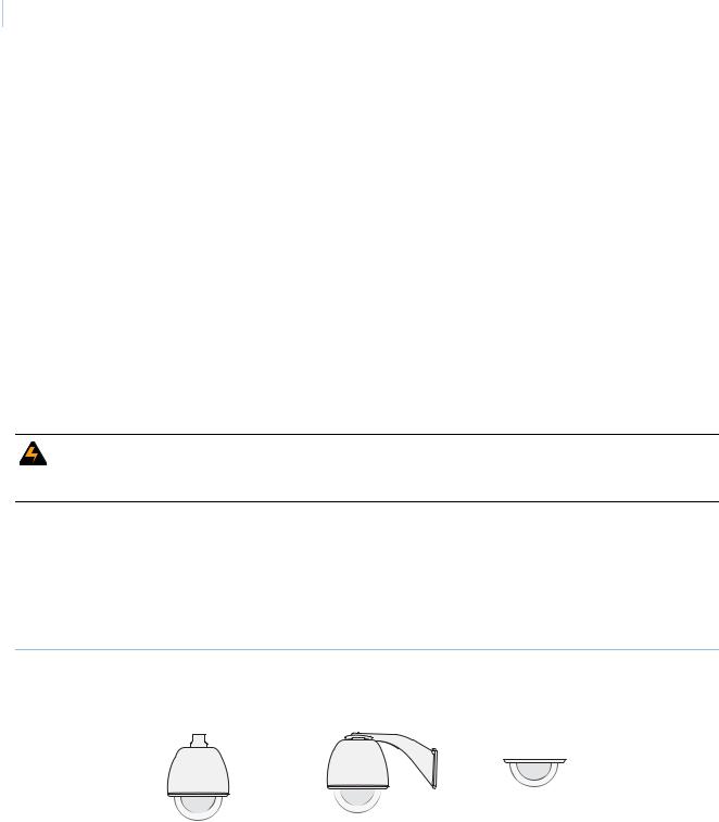
Various mounting and housing styles
There are three basic mounting styles: pendant, wall, and flush. A pendant-mount lowers a dome from a ceiling, a wall-mount extends a dome from a wall, and a flush-mount raises a dome’s dome even with a ceiling. See Figure 5. This document provides the instructions for all mounting styles.
Figure 5. Basic mounting styles
Pendant-mount |
Wall-mount |
|
Flush-mount |
|||
|
|
|
|
|
|
|
|
|
|
|
|
|
|
|
|
|
|
|
|
|
|
|
|
|
|
|
|
|
|
|
|
|
|
|
|
|
|
|
|
|
|
There are four basic housing styles: flush-mount, plastic pendant-mount, cast aluminum pendant-mount, and heavy-duty (Figure 6). Installation is generally the same for all housing styles. There are some differences, such as how the dome rings attach to the housings (Figure 28 on page 33). Where differences exist, the instructions will specify.
Chapter 2  11
11
Housings and cables
Figure 6. Basic housing styles
Flush-mount |
Plastic |
Cast aluminum |
Heavy-duty |
|
pendant-mount |
pendant-mount |
|
 Loading...