


 Loading...
Geovision GV-TVD8710, GV-TDR4700-1F, GV-TDR4702, GV-TDR2700, GV-TDR4700-0F User Manual
...GV-IP Camera
User's Manual
 GV-EBD Series
 GV-ABL / TBL Series
 GV-ADR / TDR Series
 GV-AVD / TVD Series
Before attempting to connect or operate this product, |
UBN-UM-O |
please read these instructions carefully and save this manual for future use. |

© 2019 GeoVision, Inc. All rights reserved.
Under the copyright laws, this manual may not be copied, in whole or in part, without the written consent of GeoVision.
Every effort has been made to ensure that the information in this manual is accurate. GeoVision, Inc. makes no expressed or implied warranty of any kind and assumes no responsibility for errors or omissions. No liability is assumed for incidental or consequential damages arising from the use of the information or products contained herein. Features and specifications are subject to change without notice.
Note: No memory card slot or local storage function for Argentina.
GeoVision, Inc.
9F, No. 246, Sec. 1, Neihu Rd., Neihu District, Taipei, Taiwan Tel: +886-2-8797-8377
Fax: +886-2-8797-8335 http://www.geovision.com.tw
Trademarks used in this manual: GeoVision, the GeoVision logo and GV series products are trademarks of GeoVision, Inc. Windows is the registered trademark of Microsoft Corporation.
November 2019

Preface
Welcome to the GV-EBD Series IR Eyeball IP Dome, GV-ABL Series Bullet IP Camera, GV-ADR / TDR Series Mini Fixed Rugged IP Dome and GV-AVD Series Vandal Proof IP Camera User’s Manual.
This Manual is designed for the following models:
|
Model |
Model Number |
|
|
GV-EBD2702 |
|
|
GV-EBD4700 |
|
IR Eyeball Dome |
GV-EBD4711 |
|
|
GV-EBD8700 |
|
|
GV-EBD8711 |
|
|
GV-ABL2701 Series |
|
|
GV-ABL2702 |
|
|
GV-ABL2703 Series |
|
|
GV-ABL4701 Series |
|
|
GV-ABL4703 |
|
Bullet IP Camera |
GV-ABL4712 |
|
|
GV-ABL8712 |
|
|
GV-TBL2703 Series |
|
|
GV-TBL4703 |
|
|
GV-TBL4710 |
|
|
GV-TBL8710 |
|
|
GV-ADR2701 |
|
|
GV-ADR2702 |
|
|
GV-ADR4701 |
|
Mini Fixed Rugged IP Dome |
GV-ADR4702 |
|
GV-TDR2700 |
|
|
|
GV-TDR2702 |
|
|
GV-TDR4700 Series |
|
|
GV-TDR4702 |
|
|
GV-AVD2700 |
|
|
GV-AVD4710 |
|
Vandal Proof IP Dome |
GV-AVD8710 |
|
|
GV-TVD4710 |
|
|
GV-TVD8710 |
i

Contents
Naming Definition.................................................................... |
vi |
||
Note for Connecting to GV-VMS / DVR / NVR ...................... |
vii |
||
Note for Installing Camera Outdoor ..................................... |
vii |
||
Note for Powering the Camera.............................................. |
vii |
||
Note for Face Detection ........................................................ |
viii |
||
Note for People Counting ....................................................... |
ix |
||
Chapter 1 |
Introduction .......................................................... |
1 |
|
1.1 GV-EBD Series |
...................................................................................................... |
1 |
|
1.1.1 |
Packing ................................................................................................List |
2 |
|
1.1.2 |
Optional .................................................................................Accessories |
3 |
|
1.1.3 |
Overview.................................................................................................... |
4 |
|
1.1.3.1 GV-EBD2702 ...................................................................../ 4700 / 8700 |
4 |
||
1.1.3.2 |
GV-EBD4711 .............................................................................../ 8711 |
5 |
|
1.1.4 |
Installation.................................................................................................. |
6 |
|
1.1.4.1 .........................GV-EBD2702 / 4700 / 8700 Standard Installation |
6 |
||
1.1.4.2 ....................................GV-EBD4711 / 8711 Standard Installation |
9 |
||
1.1.5 |
Optional ...................................................................................Installation |
12 |
|
1.1.5.1 ............................................................................ |
GV - Mount211P |
12 |
|
1.1.5.2 ............................................................................ |
GV - Mount212P |
17 |
|
1.1.5.3 .................................................. |
GV - Mount420 + GV - Mount211P |
21 |
|
1.1.5.4 .................................................. |
GV - Mount212P + GV - Mount107 |
24 |
|
1.2 GV-ABL / TBL Series ............................................................................................ |
26 |
||
1.2.1 |
Packing ...............................................................................................List |
27 |
|
1.2.2 |
Optional ................................................................................Accessories |
28 |
|
1.2.3 |
Overview................................................................................................... |
29 |
|
1.2.3.1 ..................GV-ABL2701 / 2703 / 4701 / 4703 & TBL2703 / 4703 |
29 |
||
1.2.3.2 ............................GV-ABL2702 / 4712 / 8712 & TBL4710 / 8710 |
30 |
||
1.2.4 |
Installation................................................................................................. |
31 |
|
1.2.5 |
Optional ...................................................................................Installation |
34 |
|
1.2.5.1 .............................................................................. |
GV - Mount502 |
35 |
|
1.2.5.2 .............................................................................. |
GV - Mount503 |
37 |
|
ii

|
1.2.5.3 |
GV-Mount420 + GV-Mount503 .................................................... |
39 |
|
1.3 GV-ADR / TDR Series .......................................................................................... |
41 |
|||
|
1.3.1 |
Packing List............................................................................................... |
42 |
|
|
1.3.2 |
Optional Accessories ................................................................................ |
43 |
|
|
1.3.3 |
Overview................................................................................................... |
45 |
|
|
1.3.4 |
Installation................................................................................................. |
46 |
|
1.3.5 |
Optional Installation ........................................................................................... |
49 |
||
|
1.3.5.1 |
GV-Mount211P ...................................................................................... |
49 |
|
1.4 GV-AVD / TVD Series........................................................................................... |
53 |
|||
|
1.4.1 |
Packing List............................................................................................... |
54 |
|
|
1.4.2 |
Optional Accessories ................................................................................ |
55 |
|
|
1.4.3 |
Overview................................................................................................... |
57 |
|
|
1.4.4 |
Installation................................................................................................. |
58 |
|
|
1.4.5 |
Optional Installation................................................................................... |
60 |
|
|
1.4.5.1 GV-Mount211-2........................................................................... |
60 |
||
|
1.4.5.2 GV-Mount212-2........................................................................... |
63 |
||
|
1.4.5.3 |
GV-Mount420 + GV-Mount211-2................................................. |
66 |
|
|
1.4.5.4 |
GV-Mount606 .............................................................................. |
67 |
|
1.5 |
System Requirements........................................................................................... |
69 |
||
1.6 |
Waterproofing the Cable ....................................................................................... |
70 |
||
Chapter 2 Accessing the Camera....................................... |
72 |
|
2.1 |
Installing on a Network.......................................................................................... |
72 |
|
2.1.1 Checking the Dynamic IP Address ............................................................ |
73 |
|
2.1.2 Assigning an IP Address ........................................................................... |
74 |
2.2 |
Accessing Live View ............................................................................................. |
75 |
|
2.2.1 The Live View Window.............................................................................. |
77 |
2.3 |
Starting Recording ................................................................................................ |
77 |
2.4 |
Playing Back Recorded Videos............................................................................. |
78 |
|
2.4.1 The Playback Window............................................................................... |
79 |
iii

Chapter 3 |
Administrator Mode |
...........................................80 |
|
3.1 |
Common............................................................................................................... |
|
80 |
|
3.1.1 |
Basic Info .................................................................................................. |
80 |
|
3.1.2 |
Local Settings ........................................................................................... |
81 |
3.2 |
Network ................................................................................................................ |
|
83 |
|
3.2.1 |
.................................................................................................... |
83 |
|
3.2.2 |
|
84 |
|
3.2.3 |
|
85 |
|
3.2.4 |
|
86 |
|
3.2.5 |
|
88 |
|
3.2.6 |
|
89 |
|
3.2.7 |
|
90 |
|
3.2.8 |
|
91 |
3.3 |
Video & Audio....................................................................................................... |
|
92 |
|
3.3.1 |
|
92 |
|
3.3.2 |
Snapshot ................................................................................................... |
94 |
|
3.3.3 |
|
95 |
|
3.3.4 |
|
96 |
|
3.3.5 |
Media Stream ............................................................................................ |
97 |
3.4 |
Image |
|
99 |
|
3.4.1 ........................................................................................................ |
|
99 |
|
3.4.2 ........................................................................................................ |
|
104 |
|
3.4.3 ........................................................................................... |
Privacy Mask |
106 |
3.5 |
Intelligent............................................................................................................ |
|
107 |
|
3.5.1 ........................................................................................ |
Smart Settings |
107 |
|
................................................................................. |
Cross Line |
108 |
|
.................................................................................... |
Intrusion |
110 |
|
........................................................................... |
Object Moving |
111 |
|
................................................................................. |
Object Left |
112 |
|
..................................................................................... |
Defocus |
113 |
|
........................................................................... |
Scene Change |
114 |
|
.......................................................................... |
Face Detection |
115 |
|
........................................................................ |
People Counting |
116 |
|
3.5.2 .................................................................................. |
Advanced Settings |
117 |
iv

3.6 |
Events |
................................................................................................................ |
118 |
|
3.6.1 |
Motion Detection ..................................................................................... |
118 |
|
3.6.2 |
Tampering Alarm .................................................................................... |
120 |
|
3.6.3 |
Audio Detection....................................................................................... |
121 |
|
3.6.4 |
Alarm Input.............................................................................................. |
122 |
|
3.6.5 |
Alarm Output........................................................................................... |
123 |
3.7 |
Storage............................................................................................................... |
124 |
|
|
3.7.1 |
Storage ................................................................................................... |
124 |
|
3.7.2 |
FTP ....................................................................................................... |
126 |
3.8 |
Security............................................................................................................... |
127 |
|
|
3.8.1 |
User ........................................................................................................ |
127 |
|
3.8.2 |
Network Security..................................................................................... |
128 |
3.9 |
System |
................................................................................................................ |
131 |
|
3.9.1 |
Time........................................................................................................ |
131 |
|
3.9.2 |
Maintenance ........................................................................................... |
133 |
Chapter 4 |
Advanced Applications ................................... |
134 |
|
4.1 |
Upgrading System Firmware............................................................................... |
134 |
|
|
4.1.1 |
Using the Web Interface.......................................................................... |
135 |
|
4.1.2 Using GV-IP Device Utility....................................................................... |
136 |
|
4.2 |
Restoring to Factory Default Settings.................................................................. |
137 |
|
Chapter 5 DVR / NVR / VMS .............................................. |
138 |
|
5.1 |
Setting Up IP Cameras on GV-DVR / NVR ......................................................... |
138 |
|
5.1.1 Customizing the Basic Settings on GV-DVR / NVR................................. |
141 |
5.2 |
Setting Up IP Cameras on GV-VMS ................................................................... |
142 |
Appendix ............................................................................... |
144 |
|
A. RTSP Multicast Protocol Support ......................................................................... |
144 |
|
B. |
RTSP Protocol Support ........................................................................................ |
144 |
C. |
HTTP Protocol Support ........................................................................................ |
144 |
D. Compatible Versions of GV-VMS / DVR / NVR..................................................... |
145 |
|
E. |
GV-Mount Dimensions ......................................................................................... |
146 |
F. |
GV-Mount300-2 / 310-2 ........................................................................................ |
149 |
G. |
Screw Position Chart............................................................................................ |
152 |
v

Naming Definition
GV-DVR / NVR |
GeoVision Analog and Digital Video Recording Software. The GV- |
|
DVR also refers to GV-Multicam System or GV-Hybrid DVR. |
|
|
GV-VMS |
GeoVision Video Management System for IP cameras. |
|
|
vi
Note for Connecting to GV-VMS / DVR / NVR
The GV-IPCAM in this Manual is designed to work with and record on GV-VMS / DVR / NVR, a video management system.
Once the camera is connected to the GV-VMS / DVR / NVR, the resolution set on the GV-VMS / DVR / NVR will override the resolution set on the camera’s Web interface. You can only change the resolution settings through the Web interface when the connection to the GV-VMS / DVR / NVR is interrupted.
The login password of the camera cannot contain the character “&” or any whitespace when connecting to GV-VMS.
The Video Analytic features under Intelligent (see 3.5 Intelligent) cannot be integrated with GV-VMS / DVR / NVR.
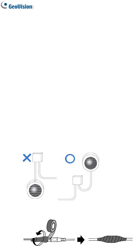
Note for Installing Camera Outdoor
When installing the camera outdoor, be sure that:
1.The camera is set up above the junction box to prevent water from entering the camera along the cables.
2.Any PoE, power, audio and I/O cables are waterproofed using waterproof silicon rubber or the like.
3.The screws are tightened and the cover is in place after opening the camera cover.
Note for Powering the Camera
The camera is powered by PoE or a power adapter. If you want to power the camera using the power connector, an optional power adapter is required.
vii
Note for Face Detection
To use the camera’s built-in face detection feature (see 3.5.1.7 Face Detection), not supported by GV-ABL2701 series / 2703 series / 4701 series / 4703, GV-ADR2701 / 2702 / 4701 / 4702, GV-TBL series, GV-TDR2702 / 4702 and GV-TVD series, it is recommended to install the camera according to the criteria listed below:
Surveillance Condition
The camera shall be installed at a site with uniform, sufficient lighting, where the face(s) to be detected are fully illuminated.
Example of Recommended Scene |
Example of Non-recommended Scene |
|
|
Camera Position
The camera shall be mounted at a recommended height of 2.5 ~ 3 m.
The camera shall be mounted with a recommended depression angle of around 10°.
The camera shall be positioned so that the face(s) to be detected are directly aligned with the lens of the camera, with a horizontal deviation of no greater than 30°, a vertical deviation of no greater than 15° and a face size of at least 120 pixels.
viii
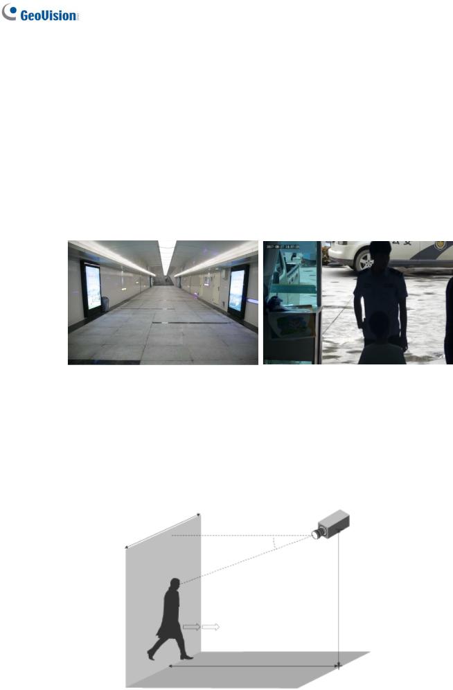
Note for People Counting
To use the camera’s built-in people counting feature (see 3.5.1.8 People Counting), not supported by GV-ABL2701 series / 2703 series / 4701 series / 4703, GV-ADR2701 / 2702 / 4701 / 4702, GV-TBL series, GV-TDR2702 / 4702 and GV-TVD series, it is recommended to install the camera according to the criteria listed below:
Surveillance Condition
The camera shall be installed at a site with uniform, sufficient lighting, where the person(s) to be counted are fully illuminated.
The camera shall be installed at an entrance or exit with an ideal width of 1 ~ 4 m, where the persons(s) to be counted move toward the lens of the camera in single file.
Example of Recommended Scene |
Example of Non-recommended Scene |
|
|
Camera Position
The camera shall be mounted at a recommended height of 3 ~ 5 m.
The camera shall be mounted with a recommended depression angle of 70 ~ 80°.
The camera shall be positioned so that the person(s) to be counted face toward the lens of the camera and are displayed on the image with a shoulder size of between 120 ~ 160 pixels.
ix

1 Introduction
Chapter 1 Introduction
1.1 GV-EBD Series
The H.265 Target Eyeball Dome is an outdoor, network camera equipped with an automatic IR-cut filter and IR LEDs for day and night surveillance. The camera adheres to IP67 standards for dust / water protection and supports H.265 video codec to achieve better compression ratio while maintaining high quality image at reduced network bandwidths. With its WDR Pro (WDR for GV-EBD2702), It can process scenes with contrasting intensity of lights and produce clear image.
For GV-EBD4711 / 8711, with their motorized lenses, the user can zoom and focus the camera from the Web interface. The camera also provides built-in micro SD card slot for local storage.
|
Model No. |
|
|
Specifications |
Description |
|
|
GV-EBD2702 |
|
|
|
|
2 MP, H.265, |
|
|
|
|
|
Low Lux, WDR |
|
|
|
|
|
|
Fixed Iris, f: 2.8 mm, |
|
|
|
|
|
|
|
|
|
GV-EBD4700 |
|
Fixed lens |
|
F/1.8, M12 Lens Mount |
4 MP, H.265, |
|
|
|
|
|||
|
|
|
Low Lux, WDR Pro |
|||
|
|
|
|
|
|
|
|
|
|
|
|
|
|
|
GV-EBD8700 |
|
|
|
Fixed Iris, f: 2.8 mm, |
8 MP, H.265, |
|
|
|
|
F/2.0, M12 Lens Mount |
Low Lux, WDR Pro |
|
|
|
|
|
|
||
|
|
|
|
|
|
|
|
GV-EBD4711 |
|
|
|
Fixed Iris, f: 2.7 ~ 12 mm, |
4 MP, H.265, |
|
|
|
|
F/1.4, Ø12 mm Lens |
Low Lux, WDR Pro |
|
|
|
|
|
|
Mount |
|
|
|
|
|
|
|
|
|
|
|
Motorized |
|
|
|
|
GV-EBD8711 |
|
varifocal lens |
|
Fixed Iris, f: 2.8 ~ 12 mm |
8 MP, H.265, |
|
|
|
|
|||
|
|
|
|
F/1.5, Ø12 mm Lens |
Super Low Lux, |
|
|
|
|
|
|
Mount |
WDR Pro |
|
|
|
|
|
|
|
1

1.1.1 Packing List
H.265 Target Eyeball Dome
Screw Kit |
Drill Template Paster |
Waterproof Rubber Set |
Download Guide |
Warranty Card
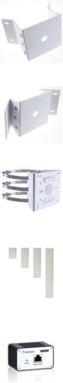
1.1.2 Optional Accessories
Optional accessories can expand the capabilities and versatility of your camera. Contact your dealer for more information.
Model Number |
Name |
Details |
GV-Mount107 |
Pendant Bracket |
Dimensions: Ø 120 x 334 mm (Ø |
(must be used with |
|
4.72” x 13.15”) |
GV-Mount212P) |
|
Weight: 0.74 kg (1.63 lb) |
|
|
|
GV-Mount211P |
Wall Mount Bracket |
Dimensions: 233 x 126 x 126 mm |
|
|
(9.2” x 5” x 5”) |
|
|
Weight: 1 kg (2.2 lb) |
|
|
|
GV-Mount212P |
Wall Box Mount |
Dimensions: Ø 126 x 36 mm (Ø |
|
|
5.0” x 1.4”) |
|
|
Weight: 0.22 kg (0.48 lb) |
|
|
|
2 |
|
|
|
|
|
1 |
Introduction |
|
|
|
||
GV-Mount300-2 |
Convex Corner Mount |
Dimensions: 137 x 233 x 160 mm |
||
|
|
(5.4” x 9.17” x 6.3”) |
||
|
|
Weight: 1.65 kg (3.64 lb) |
||
|
|
|
||
GV-Mount310-2 |
Concave Corner Mount |
Dimensions: 111.2 x 369.9 x 210 |
||
|
|
mm (2.6” x 11.4” x 6.6”) |
||
|
|
Weight: 1.65 kg (3.64 lb) |
||
|
|
|
||
GV-Mount420 |
Pole Mount Bracket |
Dimensions: Ø 120 x 120 x 53.4 |
||
(must be used with |
|
mm (Ø 4.7” x 4.7” x 2.1”) |
||
GV-Mount211P) |
|
Weight: 0.45 kg (0.99 lb) |
||
|
|
Steel Strap Diameter: Ø 67 ~ 127 |
||
|
|
mm (Ø 2.6” ~ 5”) |
||
|
|
|
||
GV-Mount704 |
Extension Tube |
Dimensions: Ø 3.5 x 10 or 20 or 30 |
||
(must be used with |
|
or 50 cm (Ø 1.38 x 3.9 or 7.9 or |
||
GV-Mount107) |
|
11.8 or 19.7”) |
||
|
|
Weight: 225 g or 360 g or 500 g or |
||
|
|
780 g (0.5 lb or 0.79 lb or 1.1 lb or |
||
|
|
1.72 lb) |
||
|
|
|
||
GV-PA191 |
Power over Ethernet (PoE) |
GV-PA191 is a Power over |
||
|
Adapter |
Ethernet (PoE) adapter designed |
||
|
|
to provide power to the IP device |
||
|
|
through a single Ethernet cable. |
||
|
|
|
||
GV-POE Switch |
GV-POE Switch is designed to provide power along with network |
|||
|
connection for IP devices. GV-POE Switch is available in various |
|||
|
models with different numbers and types of ports. |
|||
|
|
|||
Power Adapter |
Contact our sales representatives for the countries and areas |
|||
|
supported. |
|
|
|
|
|
|
|
|
3
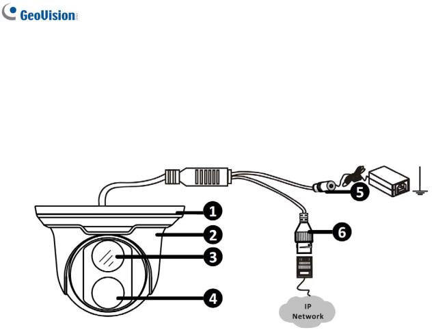
1.1.3 Overview
1.1.3.1 GV-EBD2702 / 4700 / 8700
|
Figure 1-1 |
|
|
No. |
Description |
1 |
Bottom ring |
|
|
2 |
Housing |
|
|
3 |
Lens |
|
|
4 |
Infrared indicator |
|
|
5 |
Power connector (DC 12 V) |
|
|
6 |
Ethernet connector / PoE |
|
|
4
1 Introduction
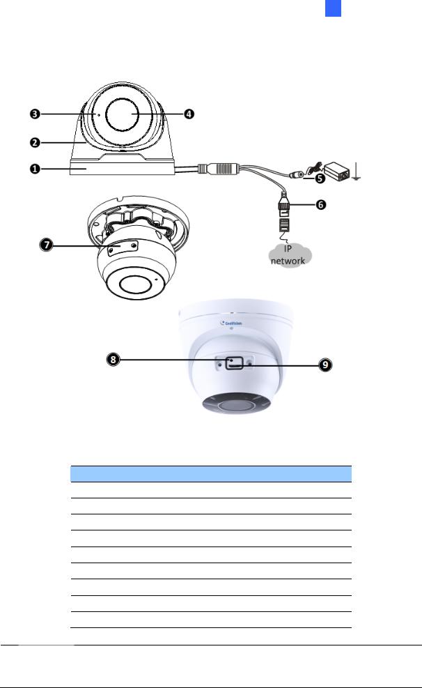
1.1.3.2 GV-EBD4711 / 8711
Figure 1-2
No. Description
1Bottom ring
2Housing
3Microphone
4Lens
5Power connector (DC 12 V)
6Ethernet connector / PoE
7Micro SD card slot and default button compartment
8Default button
9Micro SD card slot
Note: If the default button doesn’t respond after pressing for 15 seconds, reboot the camera and try again within 10 minutes of rebooting.
5
1.1.4 Installation
The Target Eyeball Dome is designed for outdoors. With the standard package, you can install the camera on the ceiling. Alternatively, you can purchase optional mounting accessories to mount the dome on a wall.
Below are the instructions for Ceiling Mount. There are two kinds of Ceiling Mount: Concealed Installation and Open Installation. In concealed installation, the cables are hidden in the ceiling. In Open Installation, the cables are led out from the open slot on the bottom ring.
1.1.4.1 GV-EBD2702 / 4700 / 8700 Standard Installation
For Concealed Installation
1.Stick the drill template paster to the ceiling and drill three holes according to the drill template.
Figure 1-3
2. Insert the screw anchors.
Figure 1-4
6
1 Introduction
3. Remove the bottom ring by turning it anticlockwise.
Figure 1-5
4. Connect the cables and secure the camera.
Figure 1-6
5. Adjust the monitoring direction.
Figure 1-7
7
6. Mount the bottom ring.
Figure 1-8
For Open Installation
Lead the cables out from the open slot on the bottom ring before screwing the camera to the ceiling as shown in Figure 1-6.
Figure 1-9
8
1 Introduction
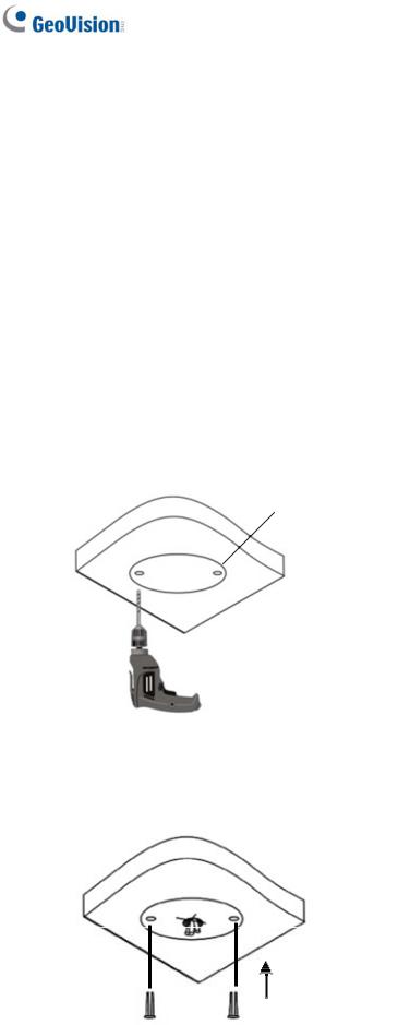
1.1.4.2 GV-EBD4711 / 8711 Standard Installation
For Concealed Installation
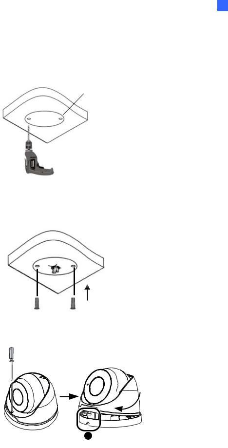
1.Stick the drill template paster to the ceiling and drill three holes according to the drill template.
Figure 1-10
2. Insert the screw anchors.
Figure 1-11
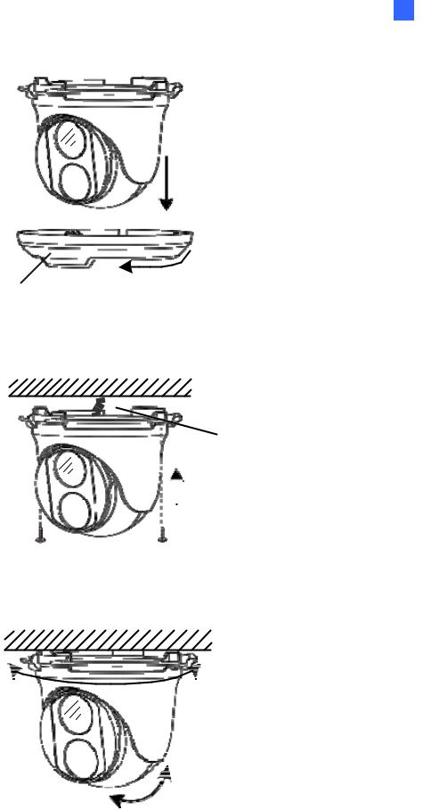
3. Loosen the fixing screw and remove the housing by turning it to the position as shown.
Figure 1-12
9
4. Secure the bottom ring to the ceiling with 3 supplied screws and connect the cable.
Figure 1-13
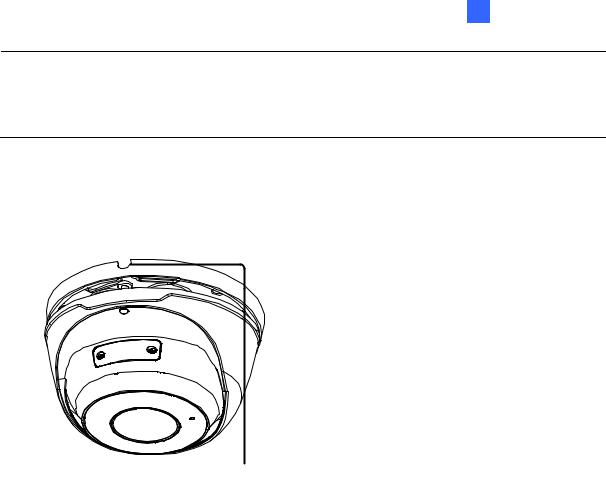
5.Mount the housing by adjusting to the position as shown and press and turn to anywhere but .
Figure 1-14
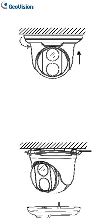
6. Adjust the monitoring direction. Then tighten the screw.
Figure 1-15
10
1 Introduction
WARNING: Make sure the housing is not dismounted from the bottom ring when adjusting the monitoring direction. Unintentional removal of the housing may result in circumstantial damages.
For Open Installation
Lead the cables out from the open slot on the bottom ring before mounting the housing as shown in Figure 1-14.
Figure 1-16
11
1.1.5 Optional Installation
You can optionally purchase the following accessories to fit your mounting environment:
GV-Mount211P / GV-Mount212P for Wall Box Mount: see section 1.1.5.1 and 1.1.5.2.
GV-Mount420 + GV-Mount211P for Pole Box Mount: see section 1.1.5.3.
GV-Mount212P + GV-Mount107 for Pendant Tube Mount: see section 1.1.5.4.
GV-Mount300-2 / 310-2 for Corner Mount: see Appendix F. GV-Mount300-2 / 310-2.
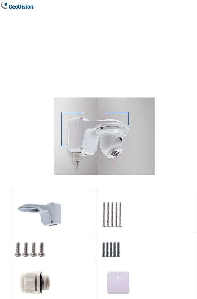
1.1.5.1 GV-Mount211P
GV-Mount211P
Figure 1-17
GV-Mount211P Packing List
GV-Mount211P Wall Mount Bracket |
Long Screw x 5 |
Short Screw x 4 |
Screw Anchor x 5 |
Plastic PG21 Conduit Connector |
Drill Template Paster |
12
1 Introduction
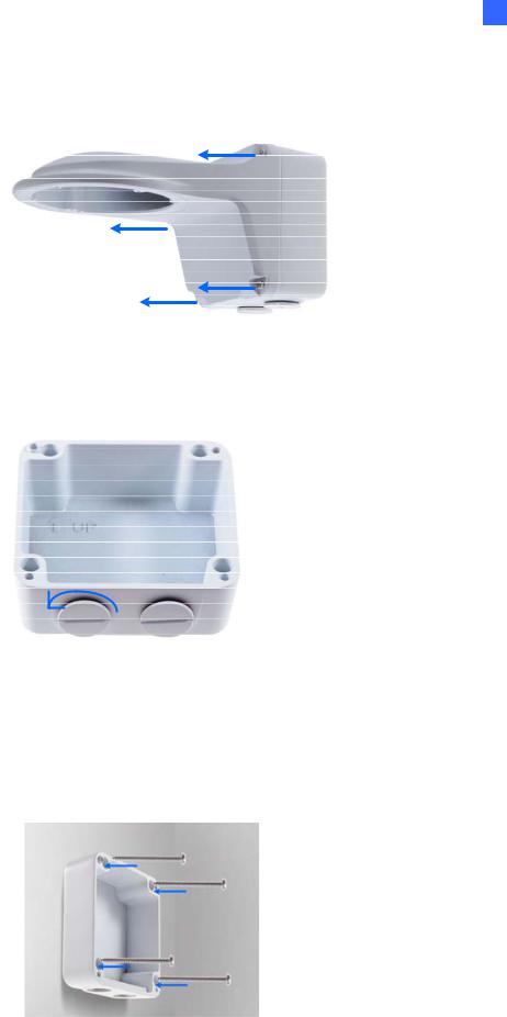
1.Unscrew the bracket.
Figure 1-18
2.Loosen the indicated area by turning it anticlockwise.
Figure 1-19
3.Stick the drill template paster to the wall with the arrow pointing up.
4.Drill 4 holes according to the sticker and insert the 4 screw anchors to the 4 holes.
5.Secure the power box to the wall with 4 long screws
Figure 1-20
13
6.Remove the bottom ring by turning it anticlockwise.
Figure 1-21
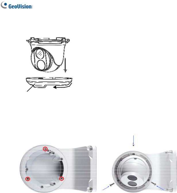
7.Secure the camera to the wall mount bracket with the provided short screws according to the screw position for each model:
GV-EBD4700 / 4711 / 8700 / 8711
Figure 1-22
14

1 Introduction
GV-EBD2702
Figure 1-23
GV-ADR2701 / 4701
Figure 1-24
GV-ADR2702 / ADR4702 / TDR2700 / TDR2702 / TDR4700 / TDR4702
Figure 1-25
15
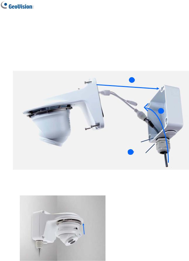
8.Thread the Ethernet cable through the PG21 conduit connector and the power box as shown in No. 8, Figure 1-26. Then connect the cable to the camera. To waterproof the cable, see 1.6 Waterproofing the Cable.
9.Rotate the plastic ring to secure the conduit connector to the power box. Screw in the cap as shown in No. 9, Figure 1-26.
10.Screw the wall mount bracket to the power box as shown in No. 10, Figure 1-26.
Figure 1-26
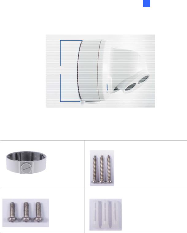
11. Mount the bottom ring.
Figure 1-27
16
1 Introduction
1.1.5.2 GV-Mount212P
GV-Mount212P
Figure 1-28
GV-Mount212P Packing List
GV-Mount212P Wall Box Mount |
Long Screw x 3 |
Short Screw x 3 |
Screw Anchor x 3 |
17
Standard Installation
1Attach the wall box to the wall and use a marker to mark the location for the center socket and the screws. Make sure the knob points down.
Long Screw
This knob points down
Figure 1-29
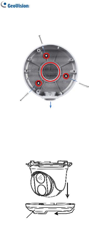
2Drill 3 holes according to the screw location. Then, drill a bigger hole at the center socket location for the Ethernet cable.
3Insert 3 screw anchors to the screw location and secure the wall box to the wall with 3 long screws.
4.Remove the bottom ring by turning it anticlockwise.
Figure 1-30
18

1 Introduction
5.Thread the Ethernet cable through the center socket and waterproof the Ethernet cable. For details, see 1.6 Waterproofing the Cable.
`
Figure 1-31
6Fit the cable into the wall box.
7Secure the camera by locking the provided short screws to the screw position for each model:
GV-EBD2702
Figure 1-32
GV-EBD4700 / 4711 / 8700 / 8711
Figure 1-33
8 Mount the bottom ring.
19
Loading...