


 Loading...
TABLE OF CONTENTS
INTRODUCTION ............................................................................. |
3 |
SYSTEM REQUIREMENT ............................................................ |
4 |
IPCAM SECURE300........................................................................... |
4 |
Network:......................................................................................... |
4 |
Recommended PC or Notebook to Access the IPCam SECURE300 |
|
....................................................................................................... |
4 |
FEATURES AND BENEFITS...................................................... |
6 |
SIMPLE TO USE ................................................................................... |
6 |
SUPPORT VARIETY OF PLATFORMS ..................................................... |
7 |
WEB CONFIGURATION......................................................................... |
7 |
REMOTE UTILITY ................................................................................ |
7 |
BROAD RANGE OF APPLICATIONS ....................................................... |
8 |
PHYSICAL DESCRIPTION .......................................................... |
9 |
FRONT PANEL...................................................................................... |
9 |
Power LED .................................................................................. |
10 |
Link LED...................................................................................... |
10 |
REAR PANEL ..................................................................................... |
11 |
Network Cable Connector ........................................................... |
11 |
DC Power Connector................................................................... |
11 |
Reset Button................................................................................. |
12 |
TOP PANEL ........................................................................................ |
13 |
Screw Hole................................................................................... |
13 |
BOTTOM PANEL ................................................................................ |
14 |
Screw Hole................................................................................... |
14 |
UNPACKING THE IPCAM SECURE300 .............................. |
15 |
CONNECTING THE IPCAM SECURE300 TO THE CAMERA STAND ..... |
16 |
HARDWARE INSTALLATION .................................................. |
17 |
1 CONNECT AN ETHERNET CABLE ..................................................... |
17 |
2 ATTACH THE EXTERNAL POWER SUPPLY......................................... |
18 |
SECURITY ........................................................................................ |
19 |
SOFTWARE INSTALLATION ................................................... |
21 |
WEB CONFIGURATION....................................................................... |
21 |
MAIN MENU IMAGE .......................................................................... |
23 |
SYSTEM ADMINISTRATION ................................................................ |
24 |
SYSTEM ADMINISTRATION ................................................................ |
24 |
System Administration – System .................................................. |
24 |
System Administration - Image .................................................... |
32 |
System Administration - Users..................................................... |
34 |
System Administration – DateTime.............................................. |
36 |
System Administration – Upload................................................. |
38 |
System Administration – E-mail................................................... |
41 |
System Administration - Information ........................................... |
43 |
System Administration - Tools ..................................................... |
44 |
VIEW IMAGE – ACTIVEX MODE ........................................................ |
45 |
VIEW IMAGE – JAVA MODE............................................................... |
47 |
IPCAM SECURE300 APPLICATION ..................................... |
49 |
APPLICATIONS................................................................................... |
50 |
IPCAM SECURE300 APPLICATION DIAGRAMS ................................ |
51 |
Home Applications....................................................................... |
51 |
IPVIEW SE APPLICATION ....................................................... |
52 |
INSTALLATION................................................................................... |
52 |
GETTING STARTED .................................................................... |
58 |
IPVIEW SE ........................................................................................ |
58 |
IPView SE control panel.............................................................. |
59 |
Minimize ...................................................................................... |
60 |
Exit............................................................................................... |
60 |
Play.............................................................................................. |
60 |
1 |
|

|
|
|
|
Scan ............................................................................................. |
60 |
|
|
|
|
Combine....................................................................................... |
60 |
|
|
|
|
About............................................................................................ |
60 |
|
HOW TO ADD A CAMERA .................................................................. |
61 |
|||
|
|
|
|
Add Camera................................................................................. |
61 |
|
HOW TO CHANGE CAMERA ............................................................... |
66 |
|||
|
|
|
|
Assign IP of New Camera............................................................ |
66 |
|
HOW TO CONNECT / DISCONNECT THE IMAGE................................... |
67 |
|||
|
|
|
|
Connect the Image ....................................................................... |
67 |
|
|
|
|
Disconnect the Image................................................................... |
70 |
|
HOW TO DELETE A CAMERA ............................................................. |
71 |
|||
|
|
|
|
Erase Camera .............................................................................. |
71 |
|
EXTRA INFORMATION........................................................................ |
72 |
|||
|
|
|
|
Extra Information ........................................................................ |
72 |
|
HOW TO ADJUST THE PROPERTY SETTING......................................... |
73 |
|||
|
|
|
|
System Configure ......................................................................... |
73 |
|
|
|
|
Camera Configure ....................................................................... |
75 |
|
|
|
|
Camera Setting ............................................................................ |
75 |
|
|
|
|
Motion Setting.............................................................................. |
76 |
|
|
|
|
Update Firmware......................................................................... |
78 |
|
HOW TO ADJUST THE RECORDING SETTING ...................................... |
79 |
|||
|
|
|
|
Motion Record ............................................................................. |
79 |
|
|
|
|
Schedule Record .......................................................................... |
79 |
|
|
|
|
Manual Record ............................................................................ |
79 |
APPENDIX ....................................................................................... |
80 |
||||
|
|
|
|
FREQUENTLY ASKED QUESTIONS |
80 |
|
A |
||||
|
B |
|
...............................................................PING YOUR IP ADDRESS |
83 |
|
|
C |
TROUBLE SHOOTING...................................................................... |
84 |
||
|
D |
|
.........................................................................TIME ZONE TABLE |
88 |
|
|
E |
|
...................................................XPLUG CONTROL INSTALLATION |
90 |
|
|
F |
.............................................ADJUST IPCAM SECURE300 FOCUS |
94 |
||
|
G |
|
..............................................................................SPECIFICATION |
95 |
|
|
HGLOSSARY OF TERMS ..................................................................... |
98 |
|||
2 |
|
||||

1
INTRODUCTION
Thank you for the purchase of the IPCam SECURE300 connecting directly to an Ethernet or Fast Ethernet. It is different from the conventional PC Camera, the IPCam SECURE300 is a standalone system with built-in CPU and web-based solutions providing a low cost solution that can transmit high quality video images for monitoring. The IPCam SECURE300 can be managed remotely, accessed and controlled from any PC/Notebook over the Intranet or Internet via a web browser. The simple installation procedures and web-based interface offers easy integration to your network application environments coupled with many applications such as remote monitoring for a cost-effective solution.
3

2
SYSTEM
REQUIREMENT
IPCam SECURE300
Network:
Local Area Network: 10Base-T Ethernet or 100Base TX Fast Ethernet
Recommended PC or Notebook to Access the IPCam SECURE300
Web Browser: |
|
System requirement: |
|
CPU: |
Pentium II, 266 MHz or above |
Memory Size: |
32 MB (64 MB recommended) |
VGA card resolution: |
800x600 or above |
•Internet Explorer 5.0 or above (ActiveX & JAVA Mode – Image View for Windows OS and JAVA Mode – Image View for other OS)
•Netscape 6.0 or above (JAVA Mode – Image View)
4
IPView SE Application:
Support OS: Win 98 SE, Win 2000, Win Me, Win XP System requirement for IPView SE:
CPU: |
Pentium III, 450 MHz or above |
Memory Size: |
128 MB (256 MB recommended) |
VGA card resolution: |
800x600 or above |
5

3
FEATURES AND
BENEFITS
This section describes the features and benefits of the IPCam SECURE300
Simple To Use
The IPCam SECURE300 is a standalone system with built-in CPU requiring no special hardware or software such as PC frame grabber cards. The IPCam SECURE300 supports both ActiveX mode (for Internet Explorer users) and Java mode (for Internet Explorer and Netscape Navigator users). Therefore, all that is required is a web browser software such as Internet Explorer 5.0 or above or Netscape 6.0 or above. Just plug and view the picture from your IPCam SECURE300 with a valid IP Address.
6

Support Variety of Platforms
The IPCam SECURE300 supports TCP/IP networking, SMTP e- mail, HTTP and other Internet related protocols, and can be utilized in a mixed operating system environment such as Windows, Unix, and Mac. It can be integrated easily into other www/Intranet applications.
Web Configuration
Applying a standard web browser, the administrator can configure and manage the IPCam SECURE300 directly from its own web page via the Intranet or Internet. Up to 64 users name and password are permitted with privilege setting controlled by the administrator.
Remote Utility
The powerful IPView SE application assigns the administrator with a pre-defined user ID and password, allowing the administrator to modify the IPCam SECURE300 settings from the remote site via Intranet or Internet. When new firmware is available, you can also upgrade remotely over the network for added convenience. Users are also allowed to monitor the image, and take snapshots.
7

Broad Range of Applications
With today’s high-speed Internet services, the IPCam SECURE300 can provide the ideal solution for live video images over the Intranet and Internet for remote monitoring. The IPCam SECURE300 allows remote access from a web browser for live image viewing and allows administrator to manage and control the IPCam SECURE300 anywhere and any time in the world. Apply the IPCam SECURE300 to monitor various objects and places such as homes, offices, banks, hospitals, child-care centers, amusement parks and other varieties of industrial and public monitoring. The IPCam SECURE300 can also be used for intruder detection; in addition, it can capture still images for archiving and many more applications.
8

4
PHYSICAL
DESCRIPTION
This section describes the externally visible features of the IPCam SECURE300.
Front Panel
Link LED
Power LED
9
Power LED
The Power LED is positioned on the right side of the IPCam SECURE300’s lens while facing the IPCam SECURE300.
A steady blue light confirms that the IPCam SECURE300 is powered on.
Link LED
The Link LED is positioned on the right side of the IPCam SECURE300’s lens while facing the IPCam SECURE300. It is located right of the Power LED
A steady orange light confirms that the camera has good connection to LAN connectivity.
Dependent on the data traffic the LED will begin to flash to indicate that the IPCam SECURE300 is receiving/sending data from/to the network.
10
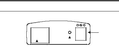
Rear Panel
10/100 Ethernet
Reset
DC 5V
DC Power
Connector
Network Cable |
Reset Button |
Connector |
|
Network Cable Connector
The IPCam SECURE300’s rear panel features an RJ-45 connector for connections to 10Base-T Ethernet cabling or 100Base-TX Fast Ethernet cabling (which should be Category 5 twisted-pair cable). The port supports the NWay protocol, allowing the IPCam SECURE300 to automatically detect or negotiate the transmission speed of the network.
DC Power Connector
The DC power input connector is located on the IPCam SECURE300’s rear panel, and is labeled DC 5V with a single jack socket to supply power to the IPCam SECURE300. Power will be generated when the power supply is connected to a wall outlet.
11
Reset Button
Reset will be initiated when the reset button is pressed once, and Power LED begins to flash.
Factory Reset will be initiated when the reset button is pressed continuously for three seconds or when Power LED begins to light up. Release the reset button and the Power LED will begin to flash, indicating the IPCam SECURE300 is changing to factory reset. When factory reset is completed, the IPCam SECURE300 will be set to default value. The IP address will also return to the default setting as 192.168.0.20.
12
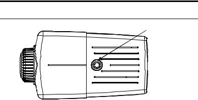
Top Panel
Screw Hole
Screw Hole
Located on the top panel of the IPCam SECURE300, the screw hole is used to connect the camera stand onto the IPCam SECURE300 by attaching the screw head on the camera stand into the screw hole of the IPCam SECURE300.
13
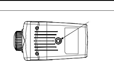
Bottom Panel
Screw Hole
Screw Hole
Located on the bottom panel of the IPCam SECURE300, the screw hole is used to connect the camera stand onto the IPCam SECURE300 by attaching the screw head on the camera stand into the screw hole of the IPCam SECURE300.
14

5
UNPACKING THE
IPCAM SECURE300
Carefully remove all items from the package. In addition to this User’s Guide, be certain that you have:
•One IPCam SECURE300
•One Installation CD-ROM
•One Quick Installation Guide
•One DC power adapter suitable for your country’s electric power
•One Camera Stand
•One RJ-45 Ethernet Cable
15
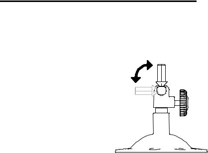
Connecting the IPCam SECURE300 to the Camera Stand
The IPCam SECURE300 comes with a camera stand (optional) with a
swivel ball screw head that can be attached to the 's bottom
screw hole. Attach the camera stand to the IPCam SECURE300 and station
it for your application. There are three holes located in the base of the camera stand allowing the IPCam SECURE300 to
be mounted on the ceiling or any wall securely.
16
6
HARDWARE
INSTALLATION
This section describes the Hardware installation procedure for the IPCam SECURE300.
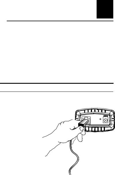
1 Connect an Ethernet cable
Connect an Ethernet cable to the network cable connector located on the IPCam SECURE300’s rear panel, and then attach it to the network.
10/100 Ethernet
Reset
DC 5V
17
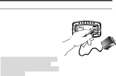
2 Attach the external power supply
Attach the external power supply to the DC power input connector located on
IPCam SECURE300’s rear panel, and then connect it to your local power supply.
Note:
Confirm power source is supplied from the LED indicators label Power on the IPCam SECURE300 Is illuminated.
10/100 Ethernet
V
18

7
SECURITY
To ensure the highest security and prevent unauthorized usage of the IPCam SECURE300 the Administrator has the exclusive privilege to access the System Administration for settings and control requirements to allow users the level of entry and authorize the privileges for all users. The IPCam SECURE300 supports multi-level password protection and access to the IPCam SECURE300 is strictly restricted to define the user who has a "User Name" and "User Password" that is assigned by the Administrator.
Administrator can release a public user name and password so when remote users access the IPCam SECURE300 they will have the right to view the image transmitted by the IPCam SECURE300.
Note:
Since the default settings are Null String, it is highly recommended to set the "Admin ID" and "Admin Password" when you are the first time to use the IPCam SECURE300. Once the ID and Password are defined, only the administrator has the access to management the IPCam SECURE300. This procedure should be done as soon as possible since the security features with
19
the IPCam SECURE300 will not be enabled until the "Admin ID" and "Admin Password" is defined.
20

8
SOFTWARE
INSTALLATION
This section describes the Software installation procedure of the IPCam SECURE300 for Web Configuration and IPView SE application.
Web Configuration
The IPCam SECURE300 must be configured through its built-in Web-based Configuration.
Extensive knowledge of LAN will be helpful in setting up the IPCam SECURE300
From the web browser, enter the default IP address to access the Welcome screen of the IPCam SECURE300. To configure your IPCam SECURE300, type http://192.168.0.20 in the address box.
21
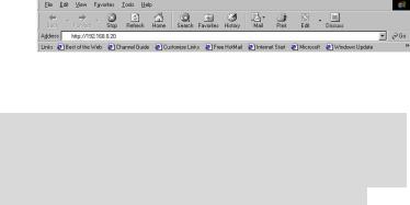
The number is the default IP address of your IPCam SECURE300. Then, press [Enter].
Note:
The PC’s IP address must correspond with the IPCam SECURE300’s IP address in the same segment for the two devices to communicate. Therefore, if your PC’s IP address doesn’t not correspond with the IPCam SECURE300’s IP address, you MUST modify your PC’s IP address at first.
22
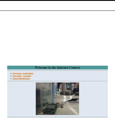
Main Menu Image
After the default IP address is entered from the browser, the IPCam SECURE300 Welcome screen will appear with a still image. There will be three options to choose from to set-up and view your IPCam SECURE300, including:
zView Image – ActiveX Mode
zView Image – Java Mode
zSystem Administration
23

System Administration
Click “System Administration” from the Welcome screen to access the settings required for the IPCam SECURE300.
There will be several options in the System menu bar to choose from to set your IPCam SECURE300, including:
zSystem
zImage
zUsers
zDate Time
zUpload
zE-mail
zInformation
zTools
System Administration
System Administration – System
The System menu contains commands for settings that are required for inputting key details to set-up the IPCam SECURE300 for operation.
Click "System" in the system administration menu bar, and the System screen will appear as illustrated below:
24
25

Click “Home” to return to Welcome Screen

Camera Name:
This field is used to enter a descriptive name for the device.
The default setting for the Camera Name is CS-xxxxxx, where xxxxxx is the last six digit of the MAC Address. The maximum length is 32 (Printable ASCII).
Location:
This field is used to enter a descriptive name for the location used by the IPCam SECURE300.
Admin:
This field is used to enter the Administrator ID along with the password to access the System Administration settings. Be sure to enter the password twice to confirm the details once in the Admin Password field and again in the Confirm Password field.
The default setting for Admin is blank space (Null String), and you need to key in the Admin ID with a maximum length of 12 (Printable ASCII) characters and enter the Admin Password with a maximum length of 8 (Printable ASCII) characters.
It is highly recommended to set the Admin ID and Admin Password as soon as possible to enable security option for the IPCam SECURE300 to function.
IP Assignment:
Important Information
Access to the IPCam SECURE300 is done through assigning a proper IP address. Please make sure to use a vacant IP address when you assign the IP address for the IPCam SECURE300. This will prevent errors from occurring if the IP address is overlapped.
27
There are two options to select from the IP Assignment:
Manually Assign or Assign Automatically Using.
Manually Assign
You can click “Manually Assign” and directly enter the IP address.
The default settings are as follows:
•Default IP – 192.168.0.20
•Subnet Mask – 255.255.255.0
•Default Gateway – 0.0.0.0
Assign Automatically Using
If your network is using RARP, BOOTP or DHCP server, you can click “Assign Automatically Using” and then click
“RARP”, “BOOTP” or “DHCP”. Under this setting the IPCam SECURE300 will automatically assign an IP address from RARP, BOOTP or DHCP server. Every time when the camera starts up, please make sure that the DHCP server is set to assign a static IP address to your camera.
If your application requires direct connection from an ADSL modem through the IPCam SECURE300’s RJ-45 LAN port, and you also have an ISP PPPoE account, click “PPPoE” option and enter the Service Name, User ID and Password into the respective fields. The IPCam SECURE300 will get an IP address from the ISP as starting up.
28
DNS IP Address:
DNS (Domain Name System) server is an Internet service that translates domain names into IP addresses. Enter at least one DNS IP Address.
Dynamic DNS:
The Dynamic DNS service allows you to alias a dynamic IP address to a static hostname in any of the domains, allowing your computer to be more easily accessed from various locations on the Internet.
LED Control:
The LED control allows user to setup the LED illumination as desired. This feature provides the flexibility when surveillance activity is ON.
There are three options as follows:
zNormal –
Power - Steady On of the LED indicator.
Link - Steady On of the LED indicator. When LAN activity is present the LED indicator will flash steadily.
zOFF –
Power - LED indicator is off
Link – LED indicator is off
zDummy –
Power - Steady On of the LED indicator.
Link - Steady On of the LED indicator with random flashing.
The default setting for the LED control is at Normal. When you have configured the LED control, the correct illumination will be set after 1 minute.
29
Loading...