


INTELLIG 1000

Includes INTELLICODE
®
2 Remote Control. Safe-T-Beam
®
System must be installed to close door.
For use only with residential sectional or one piece overhead garage doors.
Homelink
®
and Car2U
®
compatible.
For Answers and Assistance:
1.800.354.3643
or visit www.geniecompany.com
WARNING: To reduce the risk of injury to persons or damage to property – Use this opener only with a one piece
or sectional door.
SAVE THIS MANUAL FOR FUTURE REFERENCE.
INSTALLER: LEAVE THIS MANUAL WITH HOMEOWNER
IntelliG
™
1000
Model 3024 and 3024H
GARAGE DOOR OPENER
Homelink is a registered trademark of Johnson Controls Technology Company. Car2U is a registered trademark of Lear Corporation. © 2010 The Genie Company PN# 37066500753, 12/2010
OPERATION AND MAINTENANCE MANUAL
©2010 The Genie Company 12/2010
2
SAFETY INFORMATION
IMPORTANT SAFETY INSTRUCTIONS
READ AND FOLLOW ALL INSTRUCTIONS
SAVE THESE INSTRUCTIONS
CONVENTIONS USED IN THESE INSTRUCTIONS
Garage doors are large, heavy objects that move with the help of springs under high tension and electric motors. Since moving
objects, springs under tension, and electric motors can cause injuries, your safety and the safety of others depend on you reading
the information in this manual. If you have questions or do not understand the information presented, call your nearest trained
door system technician or visit our website.
The following Safety Alert symbol and signal words are used throughout this manual to call attention to and identify different
levels of hazard and special instructions.
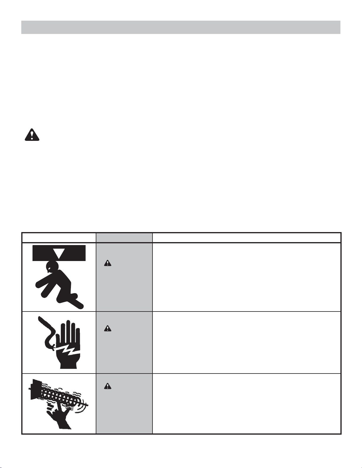
This is the safety alert symbol. This symbol alerts you to potential hazards that can kill or hurt you and others.
All safety messages will follow the safety alert symbol and the word "DANGER", "WARNING", or "CAUTION"
DANGER indicates an imminently hazardous situation which, if NOT avoided, will result in death or serious injury.
WARNING indicates a potentially hazardous situation which, if NOT avoided, could result in death or serious injury.
CAUTION indicates a potentially hazardous situation which, if NOT avoided, may result in injury or property damage.
The word NOTE is used to indicate important steps to be followed or important considerations.
Potential Hazard Effect Prevention
WARNING
Could result in
Death or Serious
Injury
Keep people clear of opening while Door is moving.
Do NOT allow children to play with the Door Opener.
Do NOT operate a Door that jams or one that has a broken
spring.
WARNING
Could result in
Death or Serious
Injury
Turn OFF power before removing opener cover.
When replacing cover, make sure wires are NOT pinched or
near moving parts.
Opener must be fully grounded.
WARNING
Could result in
Death or Serious
Injury
Do NOT try to remove, install, repair or adjust springs or
anything to which door spring parts are fastened, such as,
wood blocks, steel brackets, cables or other like items.
Installations, repairs and adjustments must be done by
a trained door system technician using proper tools and
instructions.
OVERVIEW OF POTENTIAL HAZARDS
READ THIS SAFETY INFORMATION
SAFETY FEATURES
Safe-T-Beam® (STB) Non-Contact Reversing System
Puts an invisible beam across the door opening. The door stops and reverses to the full open position if anything
passes through the beam. LED indicator lights on the powerhead and on the STBs provide a self diagnostic code
if an operational problem exists.
Safe-T-Reverse® Contact Reversing System
Automatically stops and reverses a closing door within two seconds of contact with an object.
Automatic ForceGuard™ Control
Automatically sets the force required to fully open and close the door for maximum safety.
Watch Dog™ Monitoring System
Monitors the Safe-T-Beam® system to ensure proper functionality and will automatically stop and reverse a
closing door if a problem is detected.
Manual Emergency Release
Manually releases door from door opener. Used during a power failure or other emergency to allow manual
opening and closing of door.
SmartSet™ Electronic Programming
Easily adjust the programming to reduce opening speed to a desired rate, vary limits and force, and program new
remotes.
Automatic Lighting System
Two bulb lighting system supplies up to 200 Watts of light for safer evening exits and entries. Turns ON when
door is activated and automatically turns OFF 4 minutes later.
Integrated Motion Detection (Not available on all models)
Select units have motion detection built into the powerhead. Lights automatically turn ON when motion is
detected for much safer movement through the garage. Lights will turn OFF after 4 minutes of no motion.
©2010 The Genie Company 12/2010
3
INTELLICODE® 2 Access Security System
A new generation superior encryption system that enhances the security of the door opener by continuously
changing the access code each time the remote is used. The door opener responds to each new code only once.
An access code copied from a working system and tried again will not control the door opener.
OPENER FEATURES
Wall Console, Series III
Operates door opener from inside garage. The Wall Console has an Indicator Light with: Open/Close, Sure-Lock™,
and Independent Light Control buttons.
and Car2U® compatible. Refer to the programming instructions on page 10 and then
follow the HomeLink® or Car2U® instructions in your car owner’s manual.

TABLE OF CONTENTS
Section ....................................................................................Page
Safety Information ....................................................................................................2
Opener Features & Safety Features ................................................................... 3
Table of Contents .......................................................................................................4
Installation
Important Installation Instructions ........................................................5
1 Programming Limits & Force .............................................................6-7
Contact Reverse Test ........................................................................................... 8
2 Program IntelliCode® 2 Remote to Powerhead ............................9
Programming HomeLink®, Car2U®, IntelliCode® 1 remotes or wireless
keypads ................................................................................................................10
Reference
3 Typical Installed Illustrations ................................................................ 11-13
Powerhead & Rail Assembled View ............................................................11
Typical Sectional Door Installation ............................................................12
Typical One Piece Door Installation ...........................................................13
4 Overview of Powerhead Controls ..............................................................14
5 Overview of Remotes and Options ......................................................15-16
Lost or Stolen Remote - Clearing Memory .................................................. 15
IntelliCode® Features ........................................................................................16
Previously Installed Openers ..........................................................................16
6 Maintenance & Troubleshooting ......................................................... 17-26
Important Safety Instructions ........................................................................17
Routine Monthly Maintenance .....................................................................18
Door Balance (Spring Tension) ......................................................................18
Safe-T-Beam® System Check ..........................................................................18
Contact Reverse Test .........................................................................................18
Change Light Bulbs ...........................................................................................19
Motion Detector - Overview ........................................................................... 19
Reset - Open/Close Travel Limit .....................................................................19
Carriage Engage/Disengage ..........................................................................19
Wall Console - Overview ..................................................................................20
Optional Dual Wall Console - Installation .................................................20
Remote Battery Replacement ........................................................................21
Speed Adjustment Guide .................................................................................22
Force Adjustment Guide ..................................................................................23
Troubleshooting Guide - Operation ..................................................... 24-25
Troubleshooting Guide - Powerhead LEDs ................................................25
Reference - Wiring Diagram ..........................................................................26
Warranty ......................................................................................................................27
©2010 The Genie Company 12/2010
4
OPENER MUST BE INSTALLED WITH THE INCLUDED
WALL CONSOLE.
Safe-T-Beam® SAFETY REVERSE SYSTEM MUST BE
INSTALLED TO CLOSE DOOR.
Begin here after the opener's physical assembly
and installation has been completed.
There are no assembly or installation steps included in this manual. Contact
your Genie® Professional Dealer for an installation poster, if required, or visit
www.geniecompany.com to download a PDF file.
The following mechanical assembly tasks must be completed before continuing.
Powerhead and rail are bolted to each other (An illustration is shown on page 11)
Example illustrations of the following items are shown on pages 12 and 13
Rail end is attached to a header bracket which is attached to the garage door header
Powerhead is attached to a support frame suspended from the ceiling or ceiling joists
Both pieces of door arms are assembled and are attached to the garage door
Safe-T-Beam® sensors installed and wired
Wall console installed and wired (Shown on page 20)
Carriage is engaged to the chain or belt drive (An illustration is shown on page 11)
Powerhead is plugged into an approved power outlet
Begin programming by setting Limits (see next page.)
©2010 The Genie Company 12/2010
5
IMPORTANT INSTALLATION INSTRUCTIONS
WARNING: To reduce the risk of severe injury or death:
1. READ AND FOLLOW ALL SAFETY, INSTALLATION
AND OPERATION INSTRUCTIONS. (If you have
questions or do not understand an instruction, call
The Genie Company.)
2. Install only on a properly balanced sectional or
one piece garage door. An improperly balanced
door could cause severe injury. Have a trained door
system technician make repairs or adjustments to
cables, spring assemblies, and other hardware before
installing the opener.
3. Remove all ropes and remove or make inoperative all
locks connected to the garage door before installing
opener.
4. Where possible, install the door opener 7 feet or
more above the floor. For products having an
emergency release, mount the emergency release 6
feet above the floor.
5. Do NOT connect the opener to source of power until
instructed to do so.
6. Locate the wall console:
• Within sight of the garage door,
• At minimum height of 5 feet so small children
are not able to reach it, and
• Away from all moving parts of the door.
7. Install the Entrapment WARNING Label next to the
wall console in a prominent location.
8. After installing the opener, the door must reverse
within 2 seconds when it contacts a 1-1/2 inch high
object (or a 2 x 4 board laid flat) on the floor.
INFRARED PROTECTION FUNCTION
1. When garage door is opening, its movement will not be influenced if the Safe-T-Beam® is
obstructed.
2. If the Safe-T-Beam® is obstructed before the garage door fully closes, the door will not close.
3. When the garage door is closing, if Safe-T-Beam® is interrupted by person or obstacle, the garage
door will stop its downward travel and reverse automatically to its fully opened position.
4. Remove Safe-T-Beam® obstruction.
5. If the Safe-T-Beam® System fails, loses power, or is installed improperly, press and hold the wall
console "open/close" button until the door reaches its fully closed position. If you release the
"open/close" button on the wall console during the closing movement the door will reverse
automatically to its fully opened position.
A PDF VERSION INSTALLATION POSTER IS AVAILABLE AT WWW.GENIECOMPANY.COM
OR CALL 1-800-35-GENIE TO OBTAIN AN EMAIL PDF FILE
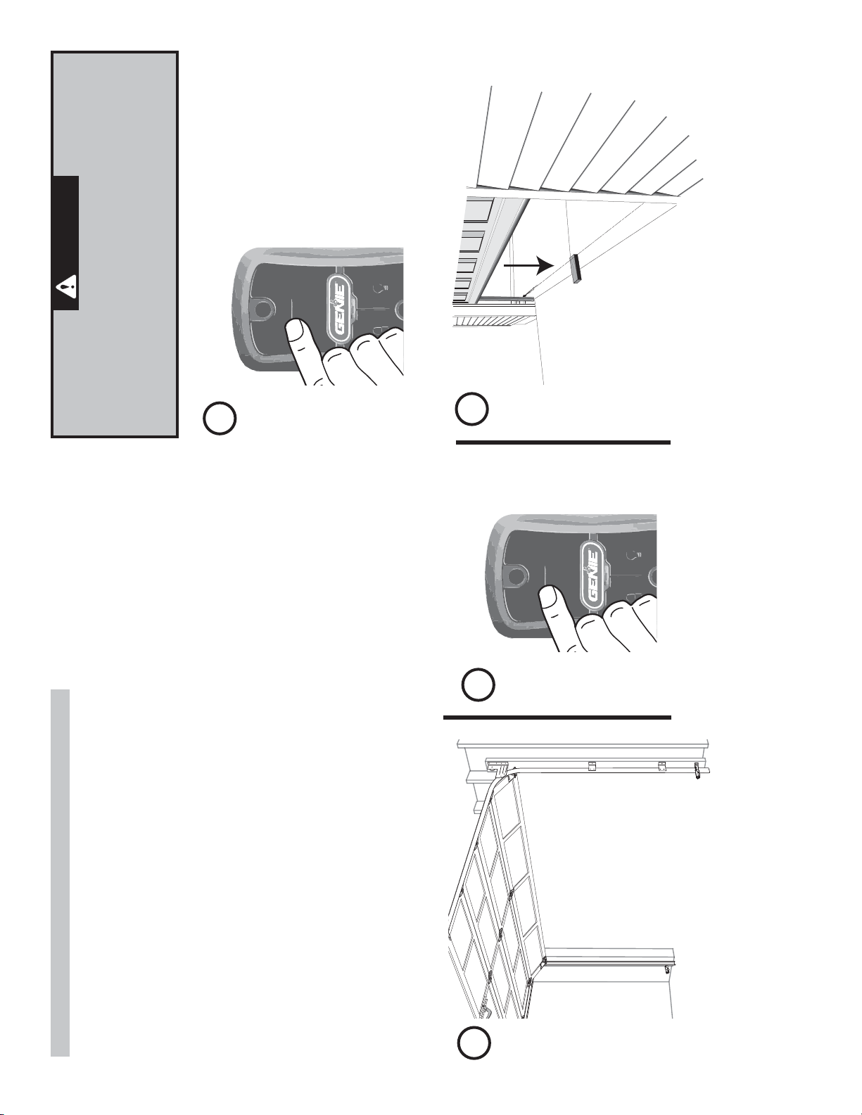
WARNING
• Make sure doorway is in view and clear of obstacles
and people to avoid injury or damage to property.
• DO NOT operate this unit from wall console before
LIMITS and FORCE are set. Severe damage to the
opener can occur.
• The bullet MUST be engaged to carriage BEFORE
setting limits. See Installation Poster (if provided) or
refer to pages 11 and 19.
NOTE: If bullet has NOT been engaged to
the carriage, do so now.
©2010 The Genie Company 12/2010
6
PROGRAM
SET
—
+
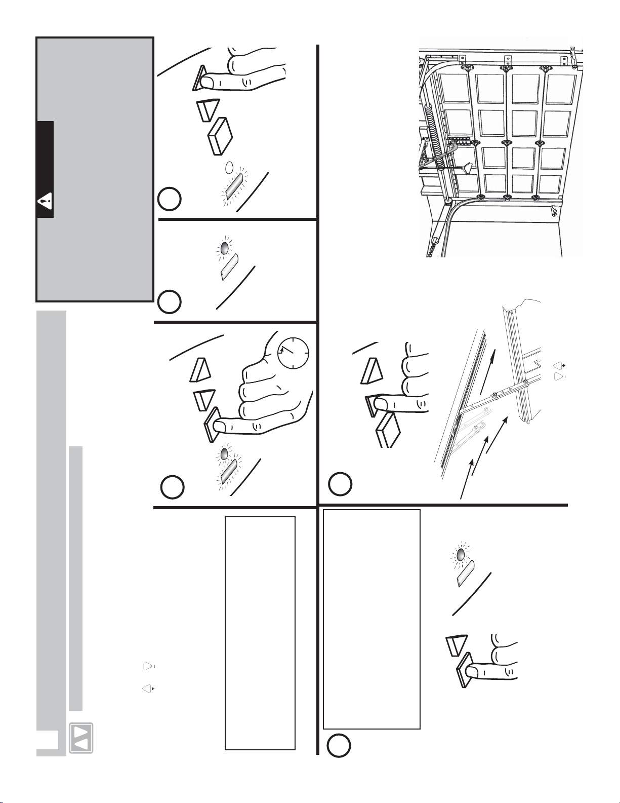
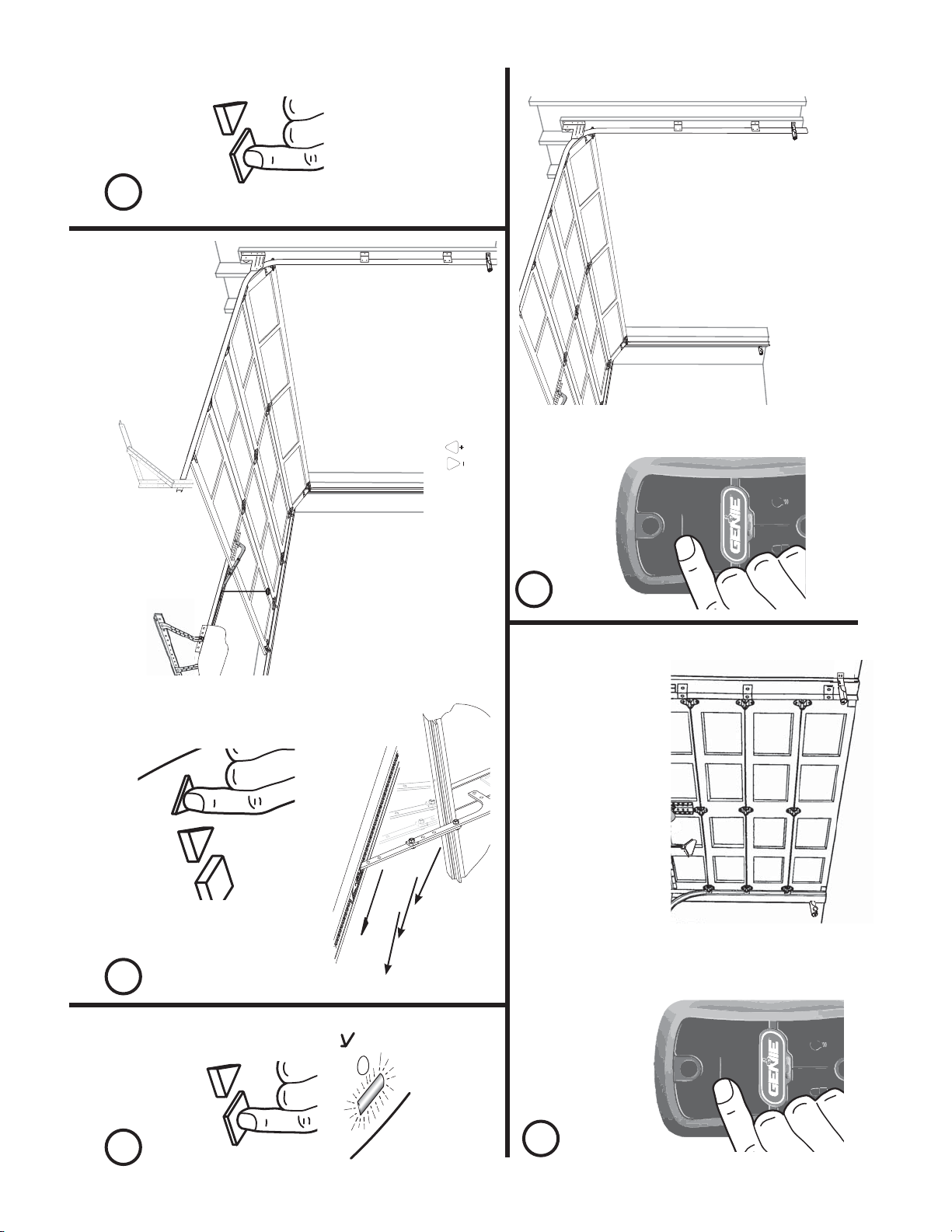
SETTING & TESTING LIMITS AND FORCE
The OPEN (UP) and CLOSE (DOWN) Door Limit positions are controlled by making
adjustments using the panel located on the bottom of the powerhead. Begin with
Step 1 and continue through Step 10. Door Force is set during the final Open/Close
cycle of these steps. The powerhead will automatically set door speed at slow if the
distance between limits is less than 6 feet. Once Limits and Force are set DO NOT use
the
or buttons to open or close door.
A) CLOSE DOOR TRAVEL LIMIT
NOTE: You can start and stop door
movement using either buttons until
door is in correct open or closed position.
Watch door move
PROGRAMMING LIMITS & FORCE
(Continuing from Installation Poster if provided)
1
RAM
SET
—
+
5
PROGRAM
SET
—
+
PRESS and HOLD
SEE BOTH
Blue LEDs
come ON
SEE round
Blue LED
come ON
SEE round Blue
LED flashing
RELEASE
1
2 3
4
NOTE: If one or both LEDs come ON RED
at this time, Limits programming menu
was not entered properly. You must exit
programming and restart.
To exit the programming function wait 30
seconds for the programming to time out.
PRESS and RELEASE
Please note that there is a 30 second timeout
between each programming step.
A programming timeout during these steps has
occured when two RED flashing LEDs appear.
In the event of a timeout please restart at Step 1.
PROGRAM
SET
—
PRESS and
RELEASE
SEE long Blue
LED come ON
If RED LED comes ON - STOP and
exit programming.
PRESS and HOLD until door is FULLY CLOSED then RELEASE
©2010 The Genie Company 12/2010
7
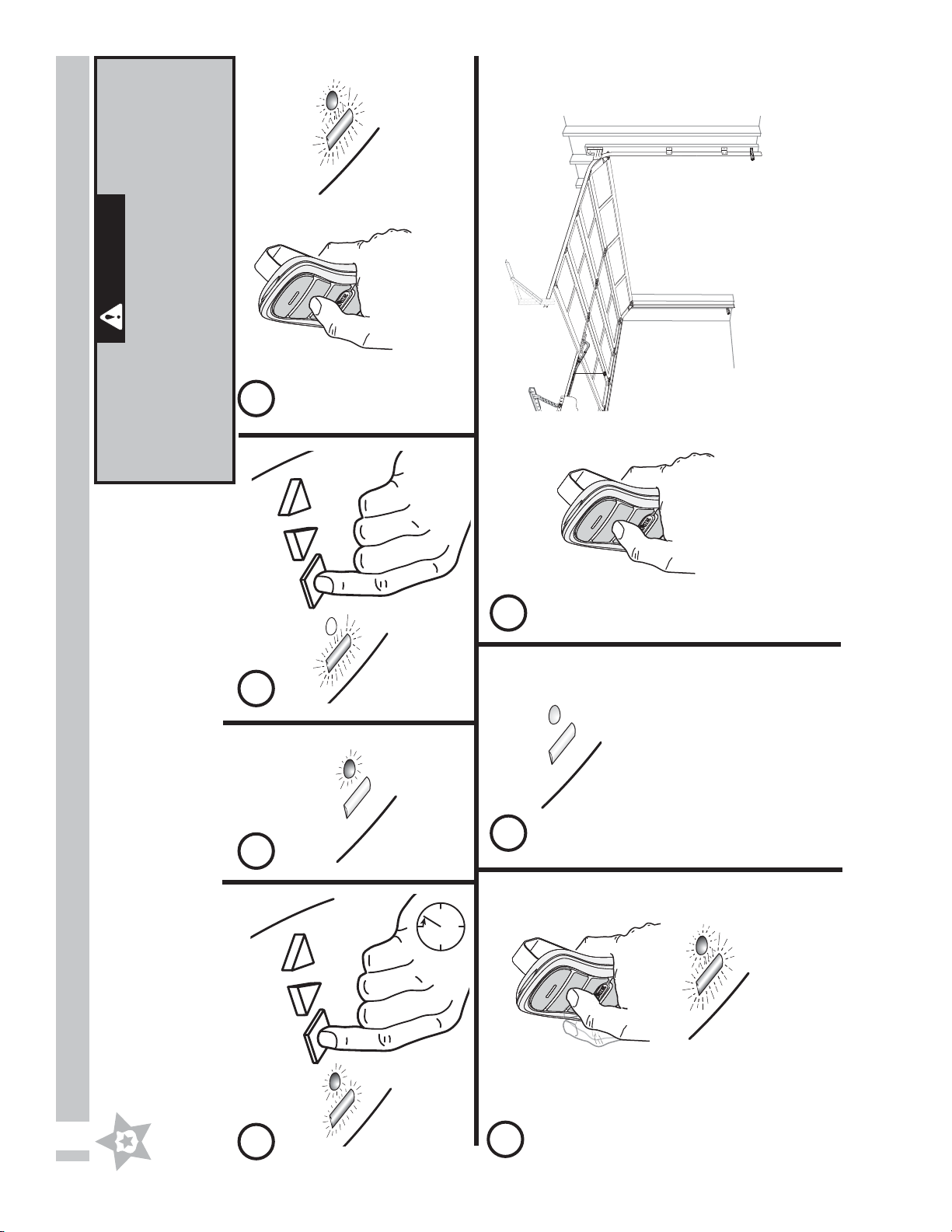
PR
OGRAM
SET
—
SEE long Blue LED
flashing
6
Watch door move
M
SET
—
+
B) OPEN DOOR TRAVEL LIMIT
DOOR CLOSES
DOOR OPENS
Door Limits are set.
Both LEDs flash Blue
and go OFF.
Continue with
Step 9 SET FORCE.
SET FORCE Force is set automatically with first full
CLOSE/OPEN door operation.
7 8
9
10
Perform a successful CONTACT REVERSE TEST and
then continue with remote programming.
NOTE: To reset LIMIT settings, repeat Steps 1-10.
PRESS and
RELEASE
On Wall Console
PRESS and RELEASE
PR
OGRAM
SET
—
NOTE: You can start and stop door
movement using either buttons until
door is in correct open or closed position.
PRESS and
RELEASE
On Wall Console
PRESS and RELEASE
PRESS and HOLD until door is FULLY OPEN then RELEASE
©2010 The Genie Company 12/2010
8
1
2
3
4
CONTACT REVERSE TEST
The Force and Limit settings on the previous page MUST be COMPLETED before Contact
Reverse testing.
1. Test.
• Open garage door using wall console.
– Place a 2" x 4" board (laid flat) under center of garage door opening.
• Close garage door using wall console.
• When door contacts board, the door must stop (within 2 seconds) and reverse direction
returning to open position.
2. Adjustment.
• If the door:
– Stops before it contacts the 2 x 4 board, it may simply be responding to an improperly set
down limit. Return to pages 6-7 and repeat steps 1 through 10 to correct down limit.
– Stops after contacting the 2 x 4 board and does not reverse it may need an adjustment to
the down limit. Return to pages 6-7 and repeat steps 1 through 10 to correct down limit.
• Test again. Repeat as necessary until door reverses upon contacting board.
WARNING
A moving door can cause serious injury or death.
1. Keep people clear of opening while door is moving.
2. Do NOT allow children to play with opener, including
wall console, remote, or wireless keypad.
3. During programming, door opener could begin to run,
so stay away from moving door and its parts.
On Wall Console
PRESS and RELEASE
DOOR OPENS
PRESS and RELEASE
Once the Contact Reverse Testing is complete continue with Programming Remotes on the next page.
©2010 The Genie Company 12/2010
9
PROGRAM
SET
—
+
PROGRAM
SET
—
+
PROGRAM INTELLICODE® 2 REMOTE TO POWERHEAD FOR HELP-1-800-35-GENIE OR WWW.GENIECOMPANY.COM
2
PRESS and HOLD
SEE BOTH
Blue LEDs
come ON
SEE round Blue
LED come ON
SEE long Purple
LED flashing
RELEASE
1 2 3 4
5
6 7
The next press of the remote will operate door.
Repeat as necessary for other remotes.
Bring remote(s) to powerhead location.
Begin with Step 1 and continue through Step 7 for each button to be programmed.
NOTE: The following instructions are for the remote(s) provided with this opener. This
remote is preset for use with the IntelliCode® 2 Access Security System. Refer to page
16 for additional information on IntelliCode® 1 and 2 remotes and how to switch from
IntelliCode® 2 to IntelliCode® 1. See page 10 for programming instructions using
IntelliCode® 1 remotes.
PRESS and
RELEASE
PRESS and
RELEASE
PRESS and
RELEASE
Basic powerhead programming is complete.
Your garage door opener is ready to use.
WARNING
A moving door can cause serious injury or death.
1. Keep people clear of opening while door is moving.
2. Do NOT allow children to play with opener, including
wall console, remote, or wireless keypad.
3. During programming, door opener could begin to run,
so stay away from moving door and its parts.
SEE both LEDs OFF
SEE both LEDs
flash Blue
PRESS and
RELEASE
SEE both LEDs
flash Purple
 Loading...