


Installer:
Leave this manual with homeowner.
Homelink® is a registered trademark of Johnson Controls Technology Company.
Car2U® is a registered trademark of
Lear Corporation.
© The Genie Company 2010. X900-786
ALWAYS AT YOUR COMMAND
Models 2022/2024/2042
GARAGE DOOR OPENERS
Includes: 2-Bulb Light System
Wall Console
Includes INTELLICODE® Remote Control Safe-T-Beam® System must be installed to close door.
For use only with sectional doors.
Homelink® and Car2U® compatible
For Answers and Assistance:
1.800.354.3643
or visit www.geniecompany.com
SAVE THIS MANUAL FOR FUTURE REFERENCE
PN# 37026500123, 2/26/2010 REV.1
SAFETY INFORMATION
OVERVIEW OF POTENTIAL HAZARDS
READ THIS SAFETY INFORMATION
Garage doors are large, heavy objects that move with the help of springs under high tension and electric motors. Since moving objects, springs under tension, and electric motors can cause injuries, your safety and the safety of others depend on the owner or user of this system to read, understand and implement the information in this manual. If you have questions or do NOT understand the information presented, contact The Genie Company or an authorized Genie® Dealer.
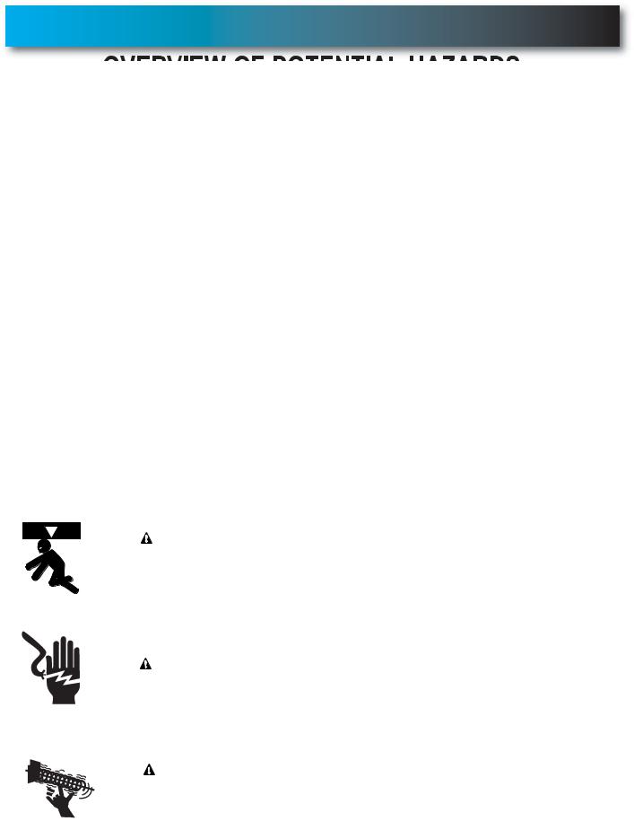
The safety alert symbol and following signal words DANGER, WARNING, and CAUTION are used throughout this manual to call attention to and identify different levels of hazard and special instructions.
 This is the safety alert symbol. This symbol is placed next to signal words and messages to help you identify important safety information
The word:
 DANGER indicates an imminently hazardous situation which, if NOT avoided, will result in death or serious injury.
 WARNING indicates a potentially hazardous situation which, if NOT avoided, could result in death or serious injury.
  CAUTION indicates a potentially hazardous situation which, if NOT avoided, may result in injury or property damage.
The word NOTE is used to indicate important steps to be followed, important considerations, or location of parts.
IMPORTANT SAFETY INSTRUCTIONS
READ AND FOLLOW ALL INSTRUCTIONS
SAVE THESE INSTRUCTIONS
|
POTENTIAL |
EFFECT |
PREVENTION |
||
|
|
HAZARD |
|||
|
|
|
|
||
|
|
|
|
WARNING: |
Keep people clear of opening while door is moving. |
|
|
|
|
||
|
|
|
|
Do NOT allow children to play with the door operator. |
|
|
|
|
|
||
|
|
|
|
Could result in Death |
|
|
|
|
|
Do NOT operate a door that jams or one that has a broken spring. |
|
|
|
|
|
or Serious Injury |
|
|
|
|
|
|
|
|
MOVING DOOR |
|
|
||
|
|
|
|
|
|
|
|
|
|
|
Turn OFF power before removing operator cover. |
|
|
|
|
WARNING: |
When replacing cover, make sure wires are not pinched or near |
|
|
|
|
|
|
|
|
|
|
Could result in Death |
moving parts. |
|
|
|
|
|
|
|
|
ELECTRICAL |
or Serious Injury |
Operator must be properly grounded. |
|
|
|
|
|
||
|
|
SHOCK |
|
|
|
|
|
|
|
|
|
|
|
|
|
WARNING: |
Do NOT try to remove, install, repair or adjust springs or anything to |
|
|
|
|
|
which door spring parts are fastened, such as, wood blocks, steel |
|
|
|
|
Could result in Death |
brackets, cables or other like items. |
|
|
|
|
or Serious Injury |
Installations, repairs and adjustments must be done by a trained door |
|
|
HIGH |
|
||
|
|
|
system technician using proper tools and instructions. |
||
|
|
SPRING |
|
||
|
|
|
|
||
2 |
|
TENSION |
|
|
|
|
|
|
PN# 37026500123 02/26/2010 REV. 1 |
||
|
|
|
|
||

TABLE OF CONTENTS
SECTION . . . . . . . . . . . . . . . . . . . . . . . . . . . . . . . . . . . . . . . . . PAGE
SAFETY INFORMATION . . . . . . . . . . . . . . . . . . . . . . . . . . . . . . . . . 2
OPENER FEATURES. . . . . . . . . . . . . . . . . . . . . . . . . . . . . . . . . . . . 3
SAFETY FEATURES . . . . . . . . . . . . . . . . . . . . . . . . . . . . . . . . . . . . 3
PRE-INSTALLATION CHECK LIST . . . . . . . . . . . . . . . . . . . . . . . 4-5
RECOMMENDED TOOLS . . . . . . . . . . . . . . . . . . . . . . . . . . . . . . . . 6
PARTS IDENTIFICATION . . . . . . . . . . . . . . . . . . . . . . . . . . . . . . . 6-7
KEY ILLUSTRATIONS. . . . . . . . . . . . . . . . . . . . . . . . . . . . . . . . . . . 8
SAFETY INSTALLATION INFORMATION. . . . . . . . . . . . . . . . . . . . 9
INSTALLATION
1 OPENER ASSEMBLY . . . . . . . . . . . . . . . . . . . . . . . . . . . . 9-11
2 OPENER INSTALLATION . . . . . . . . . . . . . . . . . . . . . . . . 12-14
3 WALL CONTROL INSTALLATION . . . . . . . . . . . . . . . . . 15-16
4 SAFE-T-BEAM® SYSTEM INSTALLATION . . . . . . . . . . . 17-18
5 CONNECTING TO POWER. . . . . . . . . . . . . . . . . . . . . . . . . 19
ADJUSTMENTS
6 LIMIT SWITCHES & FORCE ADJUSTMENT. . . . . . . . . 20-22 KEYED EMERGENCY RELEASE . . . . . . . . . . . . . . . . . . . . 21 CONTACT REVERSE TEST. . . . . . . . . . . . . . . . . . . . . . . . . 22
7 PROGRAMMING REMOTE CONTROLS. . . . . . . . . . . . . . . 23
8 BATTERY/VISOR CLIP INSTALLATION . . . . . . . . . . . . . . . 24
9 LIGHT BULB AND LENS INSTALLATION . . . . . . . . . . . . . . 24
SAFETY INSTRUCTIONS . . . . . . . . . . . . . . . . . . . . . . . . . . . . . . . 25
MAINTENANCE & TROUBLESHOOTING
10 ROUTINE MONTHLY MAINTENANCE . . . . . . . . . . . . . . . . 25 WIRING DIAGRAM . . . . . . . . . . . . . . . . . . . . . . . . . . . . . . . 26 TROUBLESHOOTING GUIDE - OPENER. . . . . . . . . . . . . . 27 TROUBLESHOOTING GUIDE - POWER HEAD LED. . . . . 28
TRANSMITTER COMPLIANCE STATEMENT . . . . . . . . . . . . . . . 29
WARRANTY . . . . . . . . . . . . . . . . . . . . . . . . . . . . . . . . . . . . . . . . . . 30
*Opener MUST be installed with the included Wall Control.
**Safe-T-Beam® Safety Reverse System MUST be installed to close door.
OPENER FEATURES
INTELLICODE® Rolling Code Security System.
An electronic rolling code system that enhances the security of the door opener by continuously changing the access code each time the remote control is used. The door opener responds to each new code only once. An access code copied from a working system and tried again will not control the door opener.
Lighted Wall Control*
Operates door opener from inside garage.
(Refer to section 3)
and Car2U® compatible.
Follow the Homelink® or Car2U® instructions in your car owner’s manual.
SAFETY FEATURES
Safe-T-Beam® Non-Contact Reversing System**.
Puts an invisible beam across the door opening. The door stops and reverses to the full open position if anything passes through the beam. Red or green LED indicator lights on the power head provide a self diagnostic code if an operational problem exists. (Refer to Section 10.)
Safe-T-Reverse® Contact Reversing System.
Automatically stops and reverses a closing door within 2 seconds of contact with an object. (Refer to Section 6.)
Safe-T-Stop® Timed Reversed System.
Automatically opens a closing door if it fails to close completely within 30 seconds.
Watch Dog™ Monitoring System.
Monitors the Safe-T-Beam® system to ensure proper functionality and will automatically stop and reverse a closing door if a problem is detected.
Automatic Lighting System.
Twin bulb lighting supplies up to 120 watts of light for safer evening exits and entries. Turns ON when door is activated and automatically turns OFF 3 minutes later.
Manual Emergency Release.
Manually releases door from door opener. Use during a power failure or other emergency to allow manual opening and closing of door. (Refer to Section 6.)
PN# 37026500123 |
02/26/2010 REV. 1 |
3 |
|
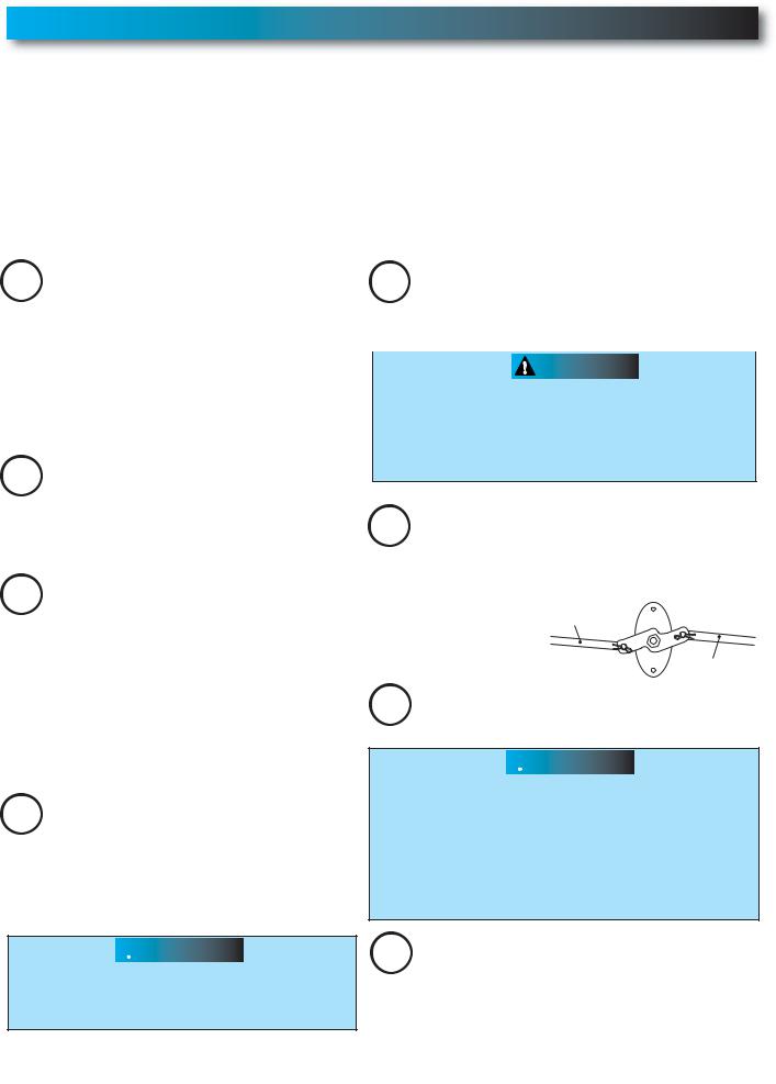
PRE-INSTALLATION CHECK LIST FOR HELP-1.800.354.3643 OR WWW.GENIECOMPANY.COM
Things to consider if you are planning to "Do-it-yourself." This opener is designed for use with SECTIONAL doors only.
In many cases you will be replacing an existing door opener with a new one, however, if this will be the first opener installed there are some pre-installation issues which need to be addressed. They are as follows:
The Genie Company recommends that you read and fully understand all information and instructions contained herein before choosing a "Do-it-yourself" installation. Any questions should be directed to The Genie Company or an authorized Genie® Dealer.
(The issue numbers below refer to the circled numbers in the illustrations on page 5.)
Check your ceiling where the power |
|
You need a properly grounded 110-120 Volt |
|
||
1 head of your new unit will be mounted. |
|
5 power supply available. The outlet should be |
|
||
Plan how you will be mounting the power head. |
|
no more than 3 feet from the power head once it is |
|
||
It is possible that ceiling joists may not be in the |
|
mounted. (Refer to Section 5.) |
|
||
position needed with respect to the garage door |
|
|
|
|
|
|
|
|
|
|
|
opener. It may be necessary to add an |
|
|
WARNING |
|
|
additional bracket and fasteners (not included |
|
DO NOT USE AN EXTENSION CORD! |
|
||
with your new door opener kit). |
|
|
|||
|
DO NOT USE A PORTABLE GENERATOR! This |
|
|||
(Refer to Section 2.) |
|
|
|||
|
product is designed to operate on |
|
|||
|
|
|
|||
|
|
standard house current. |
|
||
2Check the wall directly above the garage DO NOT USE ALTERNATE POWER SUPPLIES. door. The door opener’s header bracket
must be securely fastened to this wall. Insure that the structure will provide a strong mounting location. (Refer to Section 2.)
3Check to see if the mounting location
for the Safe-T-Beam® System is clear from
obstruction and has a wood surface available for attaching the mounting brackets. The brackets may be attached to concrete if necessary but extra tools and special fasteners (not supplied) will be required. (Refer to Section 4 and 5.)
6 To avoid damage to your door and/or opener, make sure you disable and/or
remove any door locks, ropes, and/or cables (NOT door lift cables) prior to installing your opener. (Refer to Section 1.)
Remove
Remove
7Insure that your door is properly balanced and moving freely. (Refer to Section 10.)
NOTE: Mounting brackets must be installed within code specifications.
4 |
Is your sectional garage door made of |
aluminum, light-weight steel, fiberglass |
or glass panels? Additional support bracing must be added to these type doors. If this is the case, please contact the door manufacturer or authorized dealer so that they can furnish you with a "bracing kit." (Refer to Section 2.)
 WARNING
To reduce the risk of injury to persons or damage to property - Use this opener only with sectional doors.
 WARNING
If your door jams, binds, is improperly balanced or has a broken spring, have it repaired or adjusted by a trained door system technician. Door springs, cables, pulleys, brackets and associated hardware are under extreme tension and can cause serious injury or death.
8(NOT SHOWN) If your garage does not have a separate entry door, you should consider
an emergency release kit (GER-2) for installation on your garage door.
4 |
PN# 37026500123 |
02/26/2010 REV. 1 |
|
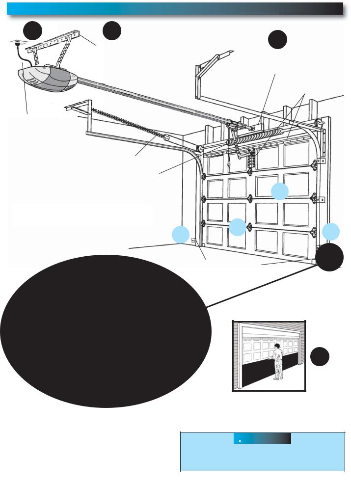
TYPICAL SECTIONAL DOOR INSTALLATION
FOR HELP-1.800.354.3643 OR WWW.GENIECOMPANY.COM
5 Pg. 19 |
1 Pg. 13 |
2 Pg. 12-13 |
|
TYPICAL SUPPORT |
ADDED |
|
BRACKET |
|
|
HEADER BRACKET |
|
|
(NOT PROVIDED) |
|
|
MOUNTING BOARD |
|
|
|
|
|
|
BRACES |
POWER CORD
(APPROX. 45 IN.) TO 120V GROUNDED OUTLET
EXTENSION SPRING
OR
TORSION SPRING
NOTE: This opener is designed for use with SECTIONAL doors only.
MAX. 6"
MIN. 5"
|
|
|
|
|
|
|
|
4 |
|
|
||
|
|
|
|
|
|
|
|
Pg. 14 |
|
|
||
|
|
|
|
|
|
|
|
|
|
|
|
|
|
|
|
|
|
|
|
|
|
|
|
|
|
|
|
|
|
|
|
|
|
|
|
|
Pg. 17-18 |
|
Pg. 17-18 |
|
|
6 |
|
|
|
|
|
||||
|
|
|
|
|
|
|
|
|
||||
|
|
|
|
|
|
|
|
|
3 |
|
||
3 |
|
|
|
|
|
|
|
|
|
|||
|
|
|
|
Pg. 11 |
|
|
|
|
|
|||
|
|
|||||||||||
|
|
|
|
|
||||||||
|
|
|||||||||||
|
|
|
|
|
|
|
|
|
|
|
|
|
|
|
|
|
|
|
|
|
|
|
|
|
|
SAFE-T-BEAM®
SENSORS
7
Pg. 25
SECTIONAL DOOR
 WARNING
To reduce the risk of injury to persons or damage to property - Use this opener only with sectional doors.
PN# 37026500123 |
02/26/2010 REV. 1 |
5 |

RECOMMENDED TOOLS
FOR HELP-1.800.354.3643 OR WWW.GENIECOMPANY.COM
|
3/16" Drill Bit |
Pencil |
Carpenter’s level |
|
|
Drill |
|
|
|
|
Ratchet |
Adjustable wrench |
Wire strippers |
|
|
|
|
|
|
|
|
Tape measure |
|
|
Step ladder |
Safety Glasses |
|
|
Hammer |
|
1/4", 7/16", 3/8" and |
|||
|
Phillips screwdriver |
|
||
|
1/2" |
Sockets |
|
|
|
|
|
||
PARTS IDENTIFICATION - Not Shown Full Size .
|
|
|
|
|
|
|
|
|
|
|
|
|
|
|
|
|
|
|
|
|
ARRANGING BOX CONTENTS FOR ASSEMBLY |
|
|||||||
|
|
|
|
|
|
ORGANISATION DU CONTENU DE LA BOÎTE POUR LE MONTAGE |
|
|||||||
|
|
|
|
|
|
DISPOSICIÓN DEL CONTENIDO DE LA BOLSA PARA EL MONTAJE |
|
|||||||
|
|
|
|
|
|
|
|
|
|
|
|
|
Remove internal boxes. |
|
|
|
|
|
|
|
|
|
|
|
|
|
|
|
|
|
|
|
|
|
|
|
|
|
|
|
|
|
Enlever les boîtes internes. |
|
|
|
|
|
|
|
|
|
|
|
|
|
|
Quite las cajas internas. |
|
|
|
|
|
|
|
|
|
|
|
|
|
|
|
|
|
|
|
|
|
|
|
|
|
|
Remove lens Box and motor power head. |
|
|||
|
|
|
|
|
|
|
|
|
|
Enlever la boîte des lentilles et la tête motorisée. |
|
|||
|
|
|
|
|
|
|
|
|
Quite la caja de la lente y el motor de la caja de control. |
|
||||
|
|
|
|
|
|
|
|
|
|
|
Carefully remove third rail (with chain or belt |
|
||
|
|
|
|
|
|
|
|
|
|
|
|
|||
|
|
|
|
|
|
|
|
|
|
|
|
|||
|
|
|
|
|
|
|
|
|
|
|
|
|||
|
|
|
|
|
|
|
|
|
|
|
|
attached) and place on floor. |
|
|
|
|
|
|
|
|
|
|
|
|
|
Enlever soigneusement le troisième rail (avec la |
|
||
|
|
|
|
|
|
|
|
|
|
|
chaîne ou courroie attachée) et le placer sur le sol. |
|
||
|
|
|
|
|
|
|
|
|
|
|
Cuidadosamente quite el tercer riel (con la |
|
||
|
|
|
|
|
|
|
|
|
|
|
cadena o correa acoplada) y ponga en el |
|
||
|
|
|
|
|
|
|
|
|
|
|
|
|
piso. |
|
|
|
|
|
|
|
|
|
|
|
|
Arrange three small boxes for easy access. |
|
||
|
|
|
|
|
|
|
|
|
|
|
Arranger les trois petites boîtes de manière à |
|
||
|
|
|
|
|
|
|
|
|
|
|
|
|
pouvoir y accéder facilement. |
|
|
|
|
|
|
|
|
|
|
|
|
Disponga las tres cajas pequeñas para tener |
|
||
|
|
|
|
|
|
|
|
|
|
|
|
|
acceso fácil. |
|
|
|
|
|
|
|
|
|
|
|
|
|
Remove rail sections not connected |
|
|
|
|
|
|
|
|
|
|
|
|
|
|
|
||
|
|
|
|
|
|
|
|
|
|
|
|
|
||
|
|
|
|
|
|
|
|
|
|
|
|
|
to chain or belt. |
|
|
|
|
|
|
|
|
|
|
|
|
|
Enlever les sections de rail non connectées |
|
|
|
|
|
|
|
|
|
|
|
|
|
|
|
à la chaîne ou courroie. |
|
|
|
|
|
|
|
|
|
|
|
|
|
Quite las secciones de riel no conectadas a |
|
|
|
|
|
|
|
|
|
|
|
|
|
|
|
la cadena o correa. |
|
|
|
|
|
|
|
|
|
Arrange rails in line and pull plastic sleeve off chain |
|
|||||
|
|
|
|
|
|
|
|
|
|
|
|
or plastic tie off belt. |
|
|
|
|
|
|
|
|
|
|
Arranger les rails en ligne et tirer sur le manchon en plastique |
|
|||||
|
|
|
|
|
|
|
|
|
pour le dégager de la chaîne ou cravate en plastique |
|
||||
|
|
|
|
|
|
|
|
|
|
|
|
|
outre de courroie. |
|
|
|
|
|
|
|
|
|
Disponga los rieles en línea y estire la camisa de plástico fuera |
|
|||||
|
|
|
|
|
|
|
|
|
|
|
de la cadena o lazo plástico de la correa. |
|
||
|
|
|
|
|
|
Follow instructions in the Installation Manual for assembly steps. |
|
|||||||
|
|
|
|
|
|
Procéder selon les instructions stipulées dans le manuel d'installation pour les étapes de |
|
|||||||
Safety Brochures |
|
|
|
|
|
|
montage à suivre. |
|
||||||
|
|
|
|
|
Box Contents Sheet |
|||||||||
|
|
|
|
|
|
|||||||||
|
|
|
|
|
|
|
|
|
|
|
|
|
|
|
|
|
|
|
|
|
|
|
|
|
|
|
|
|
|
Child can be pinned under automatic garage door. Death or serious injury can result.
•Never let child walk or run under moving door. .
•Never let child use door opener controls.
•Always keep moving door in sight.
•If person is pinned, push control button or use emergency release.
•Test door opener monthly:
Refer to your’ owner' s manual.
Place 11/2-inch object (or 2x4 laid flat) on floor.
If door fails to reverse on contact, adjust opener.
If opener still fails to reverse door, repair or replace opener.
Do not remove or paint over this label.
Mount wall control out of child's reach (at least 5 feet above floor).
Place next to wall control.
©1999
Entrapment Warning
Label
Safe-T-Beam® Source |
Safe-T-Beam® Sensor |
|
with wire |
with wire |
|
(Green LED) |
||
(Red LED) |
||
|
Safe-T-Beam®
Source/Sensor Bracket
Door Arm
Header Bracket
Three
Door Remote
Bracket
Wire
Insulated Staple |
Rail Section Clamp |
|
End Rail Section
Wall Control (varies with model)
Center Rail Section
|
|
|
|
|
|
|
|
|
|
|
|
|
|
|
|
|
|
|
|
|
|
|
|
|
|
|
|
|
|
|
|
|
|
|
|
|
|
Pro Rail (Chain) Section |
|
|
|
|
OR |
Head Rail (Chain) Section |
|
|
|
||||||||||||||||||||||||||
|
|
|
|
|
|
|
|
|
|
|
|
|
|
|
|
|
|
|
|
|
|
|
|
|
|
|
|
|
|
|
|
|
|
|
|
|
|
|
|
|
|
|
|
|
|
|
|
|
|
|
|
|
|
|
|
|
|
|
|
|
|
|
|
|
|
|
|
|
|
|
|
|
|
|
|
|
|
|
|
|
|
|
|
|
|
|
|
|
|
|
|
|
|
|
|
|
|
|
|
|
|
|
|
|
|
|
|
|
|
|
Pro Rail (Belt) Section |
Head Rail (Belt) Section |
6 |
PN# 37026500123 |
02/26/2010 REV. 1 |
|

FASTENERS - Shown Full size (See Parts List below for full description.)
BAG NO. |
|
DESCRIPTION |
QUANTITY |
|
0 |
RAIL SECTION CLAMP |
|
2 |
|
|
RAIL CLAMP BOLT – 5/16 -18 x 5/8'' |
8 |
|
|
|
HEX FLANGE NUT – 5/16 -18 |
|
8 |
|
1 |
BOLT – 5/16 -18 x 1/2'' |
|
3 |
Rail Clamp Bolt - 5/16 -18 x 5/8" |
|
|
|
|
|
2 |
CLEVIS PIN, LONG – 5/16" x 3" |
|
1 |
|
|
COTTER PIN |
|
1 |
|
|
HEADER BRACKET |
|
1 |
|
|
LAG SCREW – 5/16'' x 2'' |
|
2 |
|
3 |
HEX BOLT – 5/16 -18 x 3/4'' |
|
5 |
#10-16 x 1-1/4" Phillips Hex Screw |
|
HEX FLANGE NUT – 5/16 -18 |
|
5 |
|
|
LAG SCREW – 5/16'' x 2'' |
|
2 |
|
4 |
SELF DRILLING SCREW – 1/4 -20 x 3/4'' |
3 |
|
|
|
DOOR BRACKET |
|
1 |
|
5 |
HEX BOLT – 5/16 -18 x 3/4'' |
|
3 |
|
|
SELF LOCKING NUT – 5/16 -18 |
|
1 |
|
|
HEX FLANGE NUT – 5/16 -18 |
|
2 |
|
|
CLEVIS PIN – 5/16" x 3/4" |
|
1 |
#4-24 x 1" Pan Head |
|
|
Phillips Screw |
||
|
|
|
|
|
|
COTTER PIN |
|
1 |
|
6 |
WALL CONTROL ASSEMBLY |
|
1 |
|
|
PAN HEAD PHILLIPS SCREW – #4-24 x 1'' |
2 |
|
|
7 |
13 MM INSULATED STAPLE |
|
30 |
|
8 |
Safe-T-Beam® SOURCE/SENSOR BRACKET |
2 |
|
|
|
PHILLIPS HEX SCREW – #10-16 x 1- 1/4'' |
4 |
Lag screw - 5/16" x 2" |
|
|
|
|||
|
WIRE NUT (GREY) |
|
4 |
|
NO NUMBER |
REMOTE WITH BATTERY |
|
1 |
|
NO BAG |
Safe-T-Beam® SOURCE/SENSOR & WIRE SET |
1 |
|
|
NO NUMBER |
LIGHT COVER - WHITE |
|
2 |
Wire Nut |
|
|
|||
|
|
|
|
Clevis pin, long 5/16" x 3" |
Self Locking Nut |
Self-drilling Screw |
|
|
|
1/4 -20 x 3/4" |
|
|
||
5/16 -18 |
|
|
||
|
|
|
||
Clevis pin 5/16" x 3/4"
Cotter pin
Hex Flange Nut
5/16 -18
Hex Bolt - 5/16 -18 x 3/4" |
Hex Bolt - 5/16 -18 x 1/2" |
Hex Flange Nut
1/4 -20
MISSING ANY PARTS? Please call toll free - 1.800.354.3643
DO NOT RETURN TO POINT OF PURCHASE.
IMPORTANT! - Information needed when calling
•Model number - (located on packaging)
•Store, city, state, and date of purchase
Shoulder Bolt
5/16 -18 x 1"
PN# 37026500123 |
02/26/2010 REV. 1 |
7 |
|
1-PIECE RAIL HARDWARE ASSEMBLED VIEW
FOR HELP-1.800.354.3643 OR WWW.GENIECOMPANY.COM
Tensioner
Header
Bracket
CHAIN
|
|
TE |
|
|
NOors needt |
|
|
e doContacor |
|
|
Som g. ibutorfor |
|
|
doobracinr distrturer . |
|
TENSIONor D |
manufacuctions |
|
eath |
instr |
|
njury |
|
SPRINGus |
|
|
HIGH |
Serio |
|
Cause |
|
|
Can |
|
|
Chain
Clevis Pin, Long
& Cotter Pin
Power Cord
Rail with chain
Carriage Slide |
Power Head |
Release
Knob
Belt Clamp
Rail with belt
Carriage Slide
BELT
3-PIECE RAIL HARDWARE ASSEMBLED VIEW
|
|
|
Rail Clamps |
Rail Clamp Bolts |
|||
CHAIN |
|
|
|
End Rail |
|
|
Rail |
|
|
|
|
|
|
NOTEneedt |
|
|
|
doors tac |
or |
|
|
e . Con |
|
|
Somcing ibutorfor |
||
|
bra |
distrturer . |
|
ON |
door |
ions |
|
manufacuct |
|
||
SI |
instr |
|
|
TENor Death |
|
|
|
ry |
|
|
|
RINGnju |
|
|
|
SP rious |
|
|
|
IGHse Se |
|
|
|
H Cau |
|
|
|
Can |
|
|
|
Tensioner |
Center Rail |
|
|
|
Chain |
Clevis Pin, Long
Header & Cotter Pin
Bracket
Power Cord
Rail with chain
Power Head
Carriage Slide
|
|
|
|
|
|
|
|
H |
Serio |
|
|
TE |
BELT |
||
|
|
|
|
NOors needt |
|
||
|
|
|
|
e doContacor |
|
||
|
|
|
Som |
|
. ibutorfor |
|
|
|
|
|
bracingdistrturer . |
|
|||
|
|
ON |
door |
fac |
ions |
|
|
|
|
manu |
uct |
|
|
||
|
|
SI |
instr |
|
|
|
|
|
|
TENor Death |
|
|
|
|
|
|
|
ry |
|
|
|
|
|
|
SPR |
INGnju |
|
|
|
|
|
|
us |
|
|
|
|
|
|
HIGCause |
|
|
|
|
|
|
|
Can |
|
|
|
|
|
|
|
8 |
PN# 37026500123 |
02/26/2010 REV. 1 |
|
IMPORTANT INSTALLATION INSTRUCTIONS
 WARNING: Toreduce the risk of severe injury or death:
1
AND OPERATION INSTRUCTIONS. (If you have questions or do not understand an instruction, call The
Genie Company or an authorized Genie® Dealer.)
2.Install only on a properly balanced sectional garage door. An improperly balanced door could cause severe injury.
Have a trained door system technician make repairs or adjustments to cables, spring assemblies, and other hardware before installing the opener.
3.Remove all ropes and remove or make inoperative all locks connected to the garage door before installing opener.
4.Where possible, install the door opener 7 feet or more above the floor. For products having an emergency release, mount the emergency release 6 feet above the floor.
5.Do NOT connect the opener to source of power until instructed to do so.
6.Locate the Wall Control:
•Within sight of door,
•At minimum height of 5 feet so small children are not able to reach it, and
•Away from all moving parts of the door.
7.Install the Entrapment WARNING Label next to the Wall
Control in a prominent location. Install the Emergency Release Tag on or next to the emergency release.
8.After installing the opener, the door must reverse within
2 seconds when it contacts a 1-1/2 inch high object (or a 2 x 4 board laid flat) on the floor.
NOTE: Please follow ALL instructions in their NUMBERED sequence. Use wall control and safety sensors provided with this unit. Do NOT substitute wall control or safety sensors.
1 OPENER ASSEMBLY
FOR HELP-1.800.354.3643 OR WWW.GENIECOMPANY.COM
RAIL ASSEMBLY: Use a clean, flat surface. |
|
|
|
|
NOTE: For 1-piece rail—skip to POWER HEAD & |
|
|
|
|
RAIL ASSEMBLY. |
|
|
|
|
WARNING |
|
|
|
|
To reduce the risk of injury to persons or |
|
|
|
|
damage to property - Use this opener only |
|
|
|
#4 |
with sectional doors. |
|
|
|
|
CAUTION |
|
|
|
|
Do NOT run until opener is fully assembled and |
|
|
|
|
instructed to do so. |
|
|
|
|
NOTE: Three (3) piece rail assemblies are for a 7 |
|
|
|
|
foot high sectional door. |
|
|
|
|
Clear a workspace area to unpack and organize box |
|
|
|
|
and contents for assembly. |
|
|
|
|
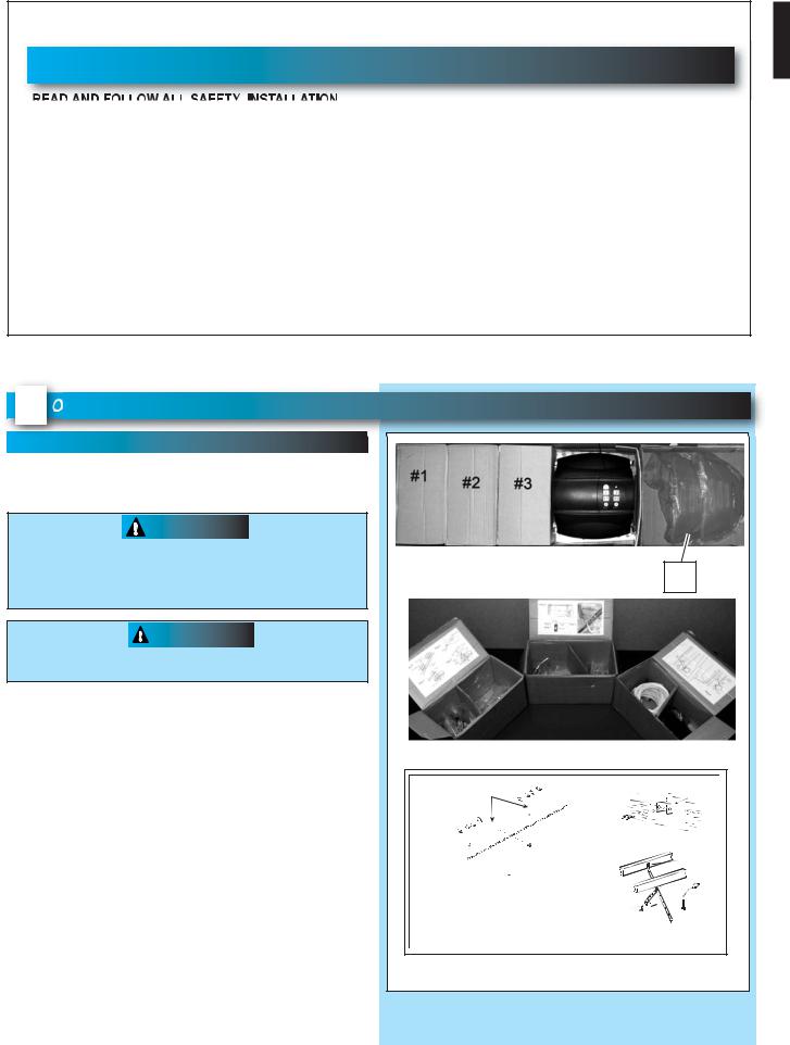
1. There are 4 boxes inside the carton. Each box is |
|
|
|
|
numbered 1 - 4. Note that some openers will |
Bag 0 |
Rail Connectors |
Bag 2 |
Header Bracket |
contain the same parts and be packaged with |
Rail Connector Bolts |
Bolts |
|
|
fewer boxes. Carefully remove the three |
|
|
|
|
|
|
|
Header Bracket |
|
internal boxes (Labeled #1, 2, and 3) and place |
|
Rail Connector Nuts |
|
|
them on the floor for easy access (Fig. 1-1). |
|
|
|
Lag Srews |
These boxes contain assembly parts and the |
Bag 1 |
Bolts |
Bag 3 |
|
contents are organized by assembly tasks. For |
Rail |
|
||
|
|
|
|
|
quick reference inside the lid of each box there is |
|
|
5/16" Nuts |
|
a label illustrating the components inside. |
|
|
& Bolts |
|
|
Power head |
|
|
|
2. Remove the motor power head and place it on |
|
|
|
|
the floor for later use. Remove box #4 and |
|
Box Label Example |
|
|
place it on the floor for later use. |
|
|
||
|
|
|
|
|
|
FIG. 1-1 |
Internal boxes. |
|
|
PN# 37026500123 |
02/26/2010 REV. 1 |
9 |
|
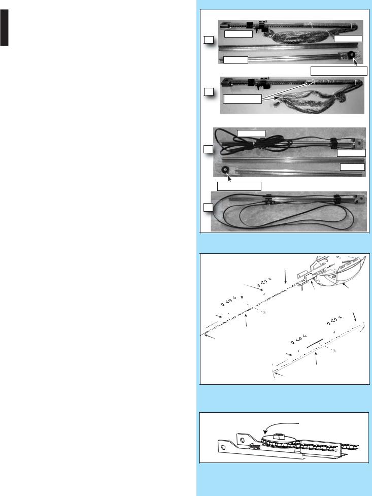
Rail Assembly for CHAIN DRIVE OPENER
NOTE: For split rail clamps, nuts, and bolts locate Bag 0 from Box 1.
3.Remove the two rail sections that are not connected to the chain and place them on floor (Fig. 1-2, A).
4.Carefully remove the third rail section with chain and plastic sleeve. Place rail section on floor and extend chain straight out
(Fig. 1-2, B). Chain and rail should extend approximately 7 feet.
5.Remove wire ties and plastic bag from chain. Leave chain extended straight out on floor.
Avoid kinks in the chain by careful handling and keeping chain flat on the floor.
6.Align the three rail sections by pulling the chain straight and wrapping it around the chain tensioner pulley (Fig. 1-3 & 1-4).
7.Attach the two rail clamps to the rail section joints with (4) bolts and nuts. After both rail clamps have been assembled to the rail sections, securely tighten the bolts and nuts.
Rail Assembly for BELT DRIVE OPENER
NOTE: For split rail clamps, nuts, and bolts locate Bag 0 from Box 1.
3.Remove the two rail sections that are not connected to the belt and place them on floor (Fig. 1-2, A).
4.Carefully remove the third rail section with belt. Place rail section on floor, remove ties on belt and extend belt straight out (Fig. 1-2, B).
Avoid twists and kinks in the belt by careful handling and keeping belt flat on the floor. Belt and rail should extend approximately 7 feet.
5.Align the three rail sections by pulling the belt straight and wrapping it around the tensioner pulley (Fig. 1-3 & 1-4).
6.Attach the two rail clamps to the rail section joints with (4) bolts and nuts. After both rail clamps have been assembled to the rail sections, securely tighten the bolts and nuts.
CHAIN DRIVE RAILS |
|
|
Chain Rail |
Center Rail |
|
A |
||
|
||
End Rail |
|
|
|
Chain Tensioner Pulley |
|
B |
|
|
Wire Tie(s) |
|
|
BELT DRIVE RAILS |
|
|
Belt Rail |
|
|
A |
Center Rail |
|
|
||
|
End Rail |
|
Tensioner Pulley |
|
|
B |
|
FIG. 1-2 Split Rail sections.
|
CHAIN |
Rail with chain |
|
||
|
|
|
|
||
|
|
Rail Clamps |
|
|
|
|
|
|
|
|
Power Head |
Rail Clamp Bolts |
|
|
|
Carriage Slide |
|
|
|
|
|
||
End Rail |
Rail |
|
|
|
|
|
|
|
|
|
|
|
N |
|
|
|
|
|
NSIO |
|
|
|
|
|
G TE |
|
|
|
|
HIGH |
SPRIN |
|
|
|
|
|
|
|
|
|
|
|
|
Center Rail |
|
|
|
|
Chain |
|
|
|
|
ng |
|
|
|
ION |
BELT |
|
|
|
G TENS |
||
|
|
|
HIGH |
SPRIN |
|
|
|
|
|
||
|
|
|
|
|
|
FIG. 1-3 Split Rail assembly.
Wrap around tensioner pulley |
FIG. 1-4 Mount chain/belt to tensioner pulley.
10 |
PN# 37026500123 |
02/26/2010 REV. 1 |
|
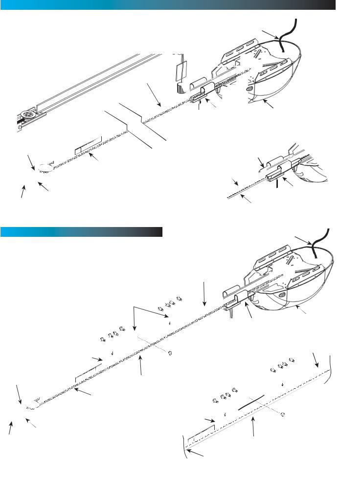
POWER HEAD & RAIL ASSEMBLY
Assembly for CHAIN DRIVE OPENER
NOTE: Handle carefully! Drive chain can slide out of rail.
NOTE: For power head and rail assembly locate Bag 1 from Box 1.
NOTE: Copy serial number from power head frame and record it on warranty page.
1.Attach rail assembly to power head by aligning the sprocket onto the motor shaft. Use (3) bolts, 5/16 -18 x 1/2" (Fig. 1-5).
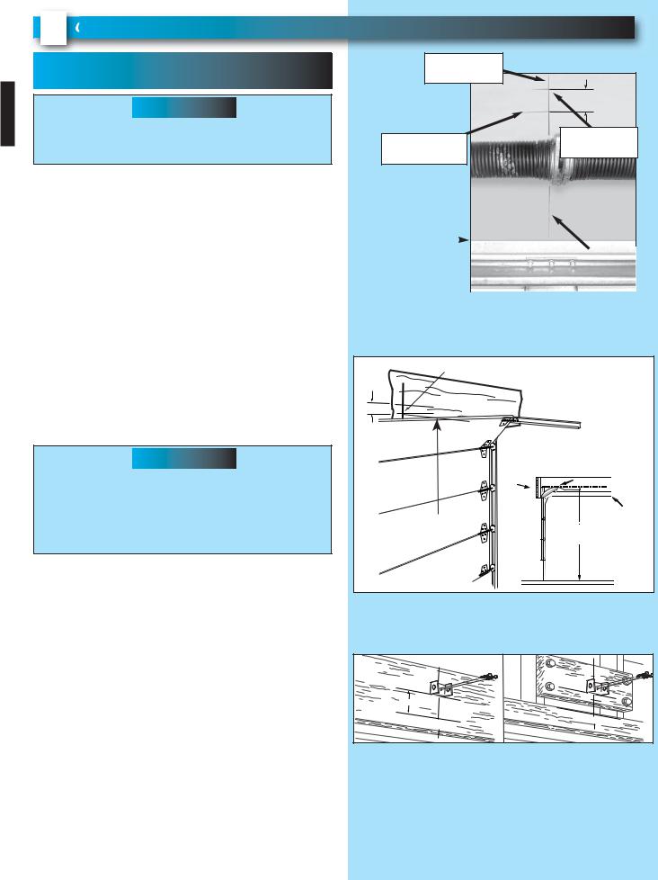
2.Tighten the chain by turning the adjustment nut clockwise. The chain adjustment nut is located in the Chain Pulley Bracket (opposite rail end from the power head) (Fig. 1-6).
3.Tighten chain until chain is approximately 1/8 inch above the base of the rail at midpoint on the rail (Fig. 1-6). Do NOT over tighten chain.
 CAUTION
You should have removed all ropes and/or cables (NOT door lift cables) and disabled the door lock already. If you have not, remove all ropes and/or cables and disable garage door lock NOW before continuing with installation (Fig. 1-8).
Set assembled power head and rail aside. Begin with Section 2 INSTALLATION.
Assembly for BELT DRIVE OPENER
NOTE: For power head and rail assembly locate Bag 1 from Box 1.
NOTE: Copy serial number from power head frame and record it on warranty page.
1.Attach rail assembly to power head by aligning the sprocket onto the motor shaft. Use (3) bolts, 5/16 -18 x 1/2" (Fig. 1-5).
2.Tighten the belt by turning the adjustment nut clockwise. The belt adjustment nut is located in the Belt Pulley Bracket (opposite rail end from the power head) (Fig. 1-7).
3.Tighten belt until belt is approximately 1/8 inch above the base of the rail at midpoint on the rail (Fig. 1-7). Do NOT over tighten belt.
 CAUTION
You should have removed all ropes and/or cables (NOT door lift cables) and disabled the door lock already. If you have not, remove all ropes and/or cables and disable garage door lock NOW before continuing with installation (Fig. 1-8).
Set assembled power head and rail aside. Begin with Section 2 INSTALLATION.
Use 5/16"-18 x 1/2"
Bolts
FIG. 1-5 Rail - Power head assembly.
|
Chain Pulley Bracket (at wall end of rail) |
|
|
Use 1/2" socket |
|
|
on adjustment nut |
|
|
Tighten nut to move pulley this direction |
|
|
Chain |
|
|
Chain |
|
|
1/8" |
|
|
T-Rail at center of rail assembly |
T-Rail |
|
|
|
FIG. 1-6 |
Chain adjustment. |
|
|
Belt Pulley Bracket (at wall end of rail) |
|
|
Use 1/2" socket |
|
|
on adjustment nut |
|
|
Tighten nut to move pulley this direction |
|
|
Belt |
|
|
Belt |
|
|
1/8" |
|
|
T-Rail at center of rail assembly |
T-Rail |
|
|
|
FIG. 1-7 |
Belt adjustment. |
|
Remove
Remove
FIG. 1-8 Disable garage door lock.
PN# 37026500123 |
02/26/2010 REV. 1 |
11 |
|
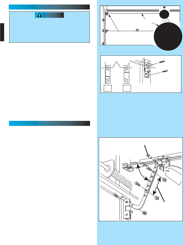
2OPENER INSTALLATION
HEADER AND DOOR
MOUNTING BRACKETS:
 WARNING
Header bracket must be fastened to garage framing. Do NOT fasten to drywall, particle board, plaster or other such materials.
1.Finding header bracket mounting location.
•Close garage door.
–Use a pencil and level.
a)Mark center of garage door (one-half overall width) on the wall with 6" vertical line at top edge of door.
b)Continue this line on wall above door for about 12" (Fig. 2-1, a).
•Raise garage door until top edge of door reaches its maximum height (Fig. 2-2).
•With door at highest point.
–Measure height from top edge of door to floor
(Fig. 2-2).
•Close door again.
•Mark height measurement on wall above door
(Fig. 2-1, c).
–Make your mark across vertical line made earlier.
•Add 2-1/2" to height mark just made on wall. This is location for header bracket (Fig. 2-1, d).
 WARNING
Door springs are under high tension. If spring or its shaft is in the way, measure 2-1/2" above spring or shaft on the garage door centerline and mark this height as your location for header bracket.
Do NOT move door spring!
NOTE: If header bracket location needs to be above header for garage door opening, you need to add a "mounting surface." A 2" x 6" board securely attached (board and fasteners not included) to wall studs on either side of your mark is sufficient (Fig. 2-3).
NOTE: For header bracket and bolts locate Bag 2 from Box 1.
NOTE: The bolts supplied in Bag 2 are designed to be used on pressure treated lumber.
2.Mounting the header bracket.
•Hold header bracket against wall (Fig. 2-3).
•Position bracket as shown.
–Place center on vertical line,
–Bottom edge on final height line.
•Mark screw hole locations on wall.
•Drill 3/16" pilot holes at each screw hole mark.
–Fasten header bracket with 2 lag screws (provided) (Fig. 2-3).
FOR HELP-1.800.354.3643 OR WWW.GENIECOMPANY.COM
b) - extend |
|
|
vertical line |
|
|
|
2-1/2" |
|
c) - door at |
d) - final |
|
height mark |
||
highest point |
||
|
|
top of door |
|
|
|
|
|
|
in closed |
|
|
|
||
|
|
|
|
a) - 6" vertical |
|
|
|
|
|
|
|
|
|
|
position |
|
line |
|
||
|
|
|
|
|
|
|
|
|
|
|
|
|
|
|
|
|
|
|
|
|
FIG. 2-1 Final height mark. |
|
|
||||
HIGHEST POINT OF TRAVEL
2-1/2"
HEADER
TRACK
SECTIONAL |
HEADER |
|
|
DOOR |
HIGHEST POINT OF TRAVEL |
||
|
|
TRACK |
|
FROM HERE |
SECTIONAL |
FROM HERE |
|
TO FLOOR |
|||
DOOR |
TO FLOOR |
||
|
FIG. 2-2 Finding highest point of travel.
final |
height |
|
|
|
final |
height |
|
|
|
mark |
|
mark |
|
|
|||
|
|
|
|
|
|
|
||
|
2- |
|
|
|
|
|
|
|
|
1/2" |
|
|
|
|
|
|
|
|
door at |
highest |
|
door at |
highest |
point |
||
|
point |
|
|
|||||
|
|
|
|
|
|
|||
|
|
|
|
|
|
|
|
|
FIG. 2-3 Header bracket mounting (on header & above header).
12 |
PN# 37026500123 |
02/26/2010 REV. 1 |
|
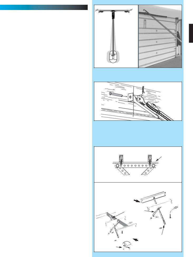
MOUNTING THE OPENER:
1.Getting started.
•Position assembled rail on wall next to header bracket (Fig. 2-4).
–Place material on floor under power head to protect from scratching. (A box, stool, or similar device may be needed to clear a torsion spring.)
NOTE: For header bracket pins locate Bag 2 from Box 1.
2.Mounting the assembly.
•Attach rail to header bracket using clevis pin and cotter pin (Fig. 2-5).
•Support power head on step-ladder to prevent interference with header mounted (torsion) spring.
NOTE: Before final attachment to ceiling, insure that assembly is in proper alignment (Fig. 2-4).
NOTE: For nuts, bolts, and lag screws locate Bag 3 from Box 1.
•On finished ceilings, locate ceiling joists or trusses using a stud finder or similar device. Attach angle iron (not provided) to joists or trusses through finish material using (provided) lag screws (Fig. 2-6).
•On unfinished ceilings or open ceilings, straps may attach directly to joists or trusses. Depending on the garage construction, extra framing material (not provided) which may be required should be installed using appropriate construction techniques (Fig. 2-6).
NOTE: Refer to your local building codes for appropriate construction techniques.
•Attach mounting straps (not provided) to ceiling using lag bolts (Fig. 2-6).
•Set height of power head to following
(Fig. 2-6).
a)Rail must clear door at door’s highest point of travel.
b)Rail must be level or at power head end slightly below level.
•Securely tighten power head mounting bolts and nuts.
•Carefully raise and lower door manually. Ensure door does not contact any section of power head or rail.
•Check that rail clamp bolts and nuts are tight.
•DO NOT PLUG OPENER IN YET!
HEADER BRACKET |
|
|
VIEW |
|
FROM ABOVE |
|
(not to scale) |
NO |
NO |
|
YES / SÍ / OUI |
FIG. 2-4 Position assembly and align.
COTTER PIN |
CLEVIS PIN |
(Chain drive |
shown) |
FIG. 2-5 Rail mounting to header bracket.
ANGLE IRON ON FINISHED CEILING |
|
|
DRYWALL |
|
Attach angle iron to beams |
UNFINISHED OR OPEN BEAM |
|
Extra framing |
|
not needed |
|
|
Mounting Straps |
|
(not provided) |
|
bolts & nuts |
|
Extra framing |
bolts & nuts |
NEEDED |
FIG. 2-6 Mounting the power head.
PN# 37026500123 |
02/26/2010 REV. 1 |
13 |
|
DOOR BRACKET: |
|
|
|
CAUTION |
|
|
|
Doors made of masonite, lightweight wood, |
|
centerline |
|
fiberglass, and sheet metal must be properly |
|
||
|
|
||
braced before mounting door opener. Contact |
|
|
|
door manufacturer or distributor for a bracing kit. |
|
centerline |
|
The Genie Company is not responsible for |
|
||
|
even with or |
||
damage caused due to improperly braced door. |
|
||
|
above top roller |
||
|
|
||
NOTE: For door bracket and bolts locate Bag 4 |
FIG. 2-7 Mounting door Bracket. |
||
from Box 2. |
|||
|
|
||
1. Finding door bracket mounting location. |
|
|
|
• Door bracket is mounted as high on door as |
centerline of top roller |
||
possible along vertical centerline and NO LOWER |
|||
|
|
||
THAN top set of rollers (Fig. 2-7). |
|
|
|
2. Mounting the door bracket. |
|
|
|
• Proper bracing should be verified at this point. |
|
|
|
– Align door bracket centered on your vertical |
|
|
|
centerline (Fig. 2-8). |
|
|
|
– Attach using 3 self-drilling screws for sheet |
A |
B |
|
metal or other light weight material. |
|||
– Use lag screws (not provided) for solid |
|
|
|
wooden sectional doors. |
FIG. 2-8 Examples of door bracket positioning. |
||
NOTE: For solid wood doors, carriage bolts WITHOUT SLOTTED HEADS (not included) may also be used for attaching door bracket.
INSTALL DOOR ARMS
NOTE: For door arm nuts and bolts, clevis and cotter pins locate Bag 5 from Box 2.
1. Attach the arms. |
|
|
• Fasten short branch of curved door arm to door |
short clevis pin & cotter pin |
|
bracket using bolt and locking nut (Fig. 2-9). |
|
|
• Fasten straight arm to carriage using clevis pin |
|
|
and cotter pin (Fig. 2-9). |
|
|
2. Connecting the arms. |
|
|
• Slide carriage back and forth to adjust arm length. |
|
|
– Position the straight arm 50º down from the |
|
|
rail. |
50° |
|
• With the arms arranged in this position, fasten |
||
|
||
arms together using bolts and nuts spaced as |
|
|
far apart as possible (Fig. 2-9). |
|
|
|
bolts as far |
|
|
apart as |
|
|
possible |
|
|
FIG. 2-9 Attaching door arms. |
14 |
PN# 37026500123 |
02/26/2010 REV. 1 |
|
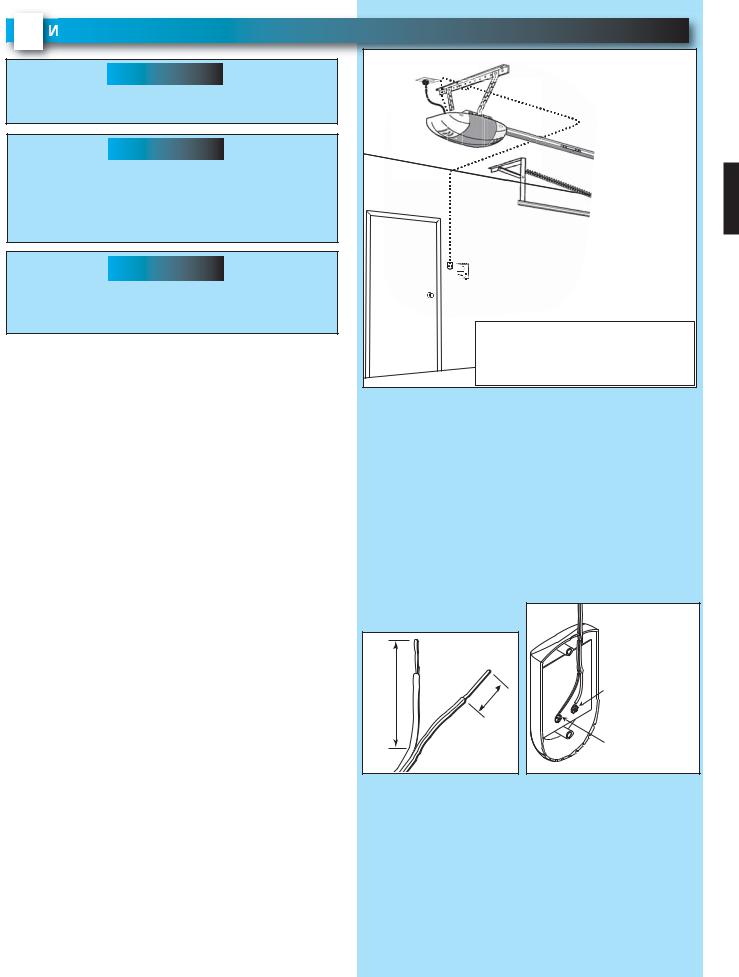
3 WALL CONTROL INSTALLATION
 WARNING
Verify there is NO power to the opener before installing Wall Control wires and Wall Control.
 CAUTION
Staples which are too tight can cut or pinch wires. Cut or pinched wires can cause the Wall Control to stop working. When using the insulated staples, make sure you fasten them only as tightly as needed to hold the wire snugly.
 WARNING
Use of any other wall control can cause the door to operate unexpectedly and the light not to work. Use only the included Wall Control.
NOTE: Wall control will not operate until limits are set.
NOTE: For Wall Control, wire and insulated staples locate Bags 6 and 7 from Box 2.
1.Wall Control location.
•Wall Control location should be in direct sight of door.
•It should be at least five feet (5') above floor to prevent small children from operating door.
•It must be away from any moving parts. (You should NOT be able to reach the garage door while standing at Wall Control.)
•Wall Control board screw connections are polarized, (+) positive and (-) negative.
2a. Wiring (If pre-wired).
•Locate Wall Control pre-wired wire ends (Fig. 3-1). (They should be located within the guidelines mentioned above.)
•Split and strip ends of wire (Fig. 3-2).
•Fasten wire to Wall Control board screws on back of Wall Control.
–Striped wire to the + (plus) terminal.
–White wire to the - (minus) terminal.
2b. Wiring (If NOT pre-wired).
•Pick a convenient location for mounting Wall Control using the guidelines mentioned above (Fig. 3-1).
•Run wire from power head to Wall Control
(Fig. 3-1).
•Split and strip ends of wire (Fig. 3-2).
•Fasten wire to Wall Control board screws on back of Wall Control.
–Striped wire to the + (plus) terminal.
–White wire to the - (minus) terminal.
FOR HELP-1.800.354.3643 OR WWW.GENIECOMPANY.COM
Wire from |
power head |
to Wall Control |
Wall |
Control |
"Entrapment" warning label
Separate |
|
entry door |
EXAMPLE ONLY! |
|
This is an example of wire routing when NOT pre-wired. Your wire routing may be different.
FIG. 3-1 Wall Control wire routing
|
|
|
or |
White |
|
|
– |
|
|
2" |
|
|
|
|
|
|
|
Black |
|
|
1/2" |
|
|
|
|
|
|
Striped |
|
|
|
+ |
or |
|
|
|
|
||
|
|
|
|
FIG. 3-2 Splitting and stripping.
PN# 37026500123 |
02/26/2010 REV. 1 |
15 |
|

3. Securely fasten wires.
•Securely fasten wires to ceiling and wall using insulated staples provided.
– Use insulated staples.
– Staples should be snug only.
• If rear cover is attached to power head, remove it.
•On power head:
–Route Wall Control wires through wire guide on power head.
–Split and strip ends of wire (Fig. 3-2 on previous page).
–Insert wire into terminal holes and lightly press in the orange locking clips above each terminal hole. (You can use a pencil or small screwdriver to comfortably press in locking clips.) The white wire into #1 terminal hole and striped wire into the #2 terminal hole.
–Confirm wire lock by lightly tugging on the wire. The wire should remain in the terminal hole.
•Do NOT install rear cover yet.
4.Mounting.
•Fasten Wall Control to wall with 2 screws (provided) (Fig. 3-4).
•Remove protective backing from "Entrapment" warning label (Fig. 3-5). The "Entrapment" label is located in the center of this manual.
–Stick label on wall near Wall Control.
Locking
Clips Terminal wire guide

 Holes
Holes
6 5 4 3 2 1
6 5 4 3 2 1


 + –
+ –
P B
InfaredSensor
(Power Head With Rear Cover Removed)
FIG. 3-3 Insert wires.
Vacation Locking Switch
|
– LOCK disables controls after |
|
1 |
door is completely closed |
|
– UNLOCK allows controls to |
||
|
||
|
work normally |
Door Control "Open/Close" Button
– Open and closes door from
2 inside garage
3
Independent Light Control
–Controls door opener lights from inside garage
–Energy-Saver shut-off turns OFF lights 3 minutes after door activation
FIG. 3-4 Mounting Wall Control.
Chil |
d |
|
|
|
|
|
|
|
|
|
|
|
|
|
|
|
|
|
|
|
|
|
|
|
|
|
|
|
|
|
|
|
|
|
|
|
|
|
|
|
|
|
|
D |
|
|
|
|
|
|
|
|
|
|
|
|
|
|
|
|
|
|
|
|
|
|
|
|
|
|
|
|
|
|
|
|
|
|
|
|
|
|
|
|
|
|
|
|
eathcan |
|
be |
|
|
|
|
|
|
|
|
|
|
|
|
|
|
|
|
|
|
|
|
|
|
|
|
|
|
|
|
|
|
|
|
|
|
||||||
|
• |
|
|
or |
|
p |
|
|
|
|
|
|
|
|
|
|
|
|
|
|
|
|
|
|
|
|
|
|
|
|
|
|
|
|
|
|
|
|
|
||||
|
|
|
|
|
ser |
in |
|
|
|
|
|
|
|
|
|
|
|
|
|
|
|
|
|
|
|
|
|
|
|
|
|
|
|
|
|
|
|
||||||
|
Ne |
|
|
n |
|
|
|
|
|
|
|
|
|
|
|
|
|
|
|
|
|
|
|
|
|
|
|
|
|
|
|
|
|
||||||||||
|
• |
|
|
v |
|
|
|
|
io |
u |
|
|
|
|
|
|
|
|
|
|
|
|
|
|
|
|
|
|
|
|
|
|
|
|
|
|
|
|
|
||||
|
|
|
|
er |
|
|
|
|
|
|
|
|
|
|
|
|
|
|
|
|
|
|
|
|
|
|
|
|
|
|
|
|
|
|
|
|
|
|
|
|
|||
|
Ne |
|
let |
|
|
s ed |
u |
|
|
|
|
|
|
|
|
|
|
|
|
|
|
|
|
|
|
|
|
|
|
|
|
||||||||||||
|
• |
|
|
v |
|
chi |
|
in |
|
nd |
|
|
|
|
|
|
|
|
|
|
|
|
|
|
|
|
|
|
|
|
|
||||||||||||
|
Alw er |
let |
|
|
|
|
|
|
er |
|
|
|
|
|
|
|
|
|
|
|
|
|
|
|
|
|
|
|
|||||||||||||||
|
• |
|
|
|
a |
|
|
|
|
ld |
|
|
jury |
|
|
|
|
|
|
|
|
|
|
|
|
|
|
|
|
|
|
|
|
||||||||||
|
If |
p |
ys |
|
|
|
|
|
wal |
|
|
can |
|
|
|
|
|
|
|
|
|
|
|
|
|
|
|
|
|
|
|||||||||||||
|
|
|
|
|
chi |
|
|
|
|
|
|
|
|
|
|
|
|
|
|
|
|
|
|
|
|
|
|||||||||||||||||
|
emer |
|
|
kee |
|
|
ld u |
|
|
k |
or |
|
|
autom |
|
|
|
|
|
|
|
|
|
|
|
||||||||||||||||||
|
|
• |
erson |
is |
p m |
|
se |
|
|
|
|
resu at |
|
|
|
|
|
|
|
|
|||||||||||||||||||||||
|
|
|
ge |
|
|
|
|
|
|
ov |
|
|
do |
run |
u |
|
lt. ic |
gara |
|
|
|
||||||||||||||||||||||
|
|
|
Test |
|
ncy pin |
n |
|
in |
g |
|
or |
|
|
|
|
|
|
|
|
|
|
|
|
|
|||||||||||||||||||
|
|
|
|
|
R |
edoor |
re |
|
|
|
|
|
|
|
|
op |
n |
der |
|
|
|
|
ge |
|
|||||||||||||||||||
|
|
|
|
|
le |
e |
|
|
|
|
do |
|
|
|
|
|
|
|
|
|
|
||||||||||||||||||||||
|
|
|
|
|
P |
|
|
|
a |
|
d, |
|
or en |
|
|
|
m |
|
|
|
door |
||||||||||||||||||||||
|
|
|
|
|
|
fer |
to |
|
|
|
|
|
|
|
|
|
pu |
|
|
|
|
|
|
|
|
|
|||||||||||||||||
|
|
|
|
|
If |
lac |
|
ope |
|
|
|
|
|
|
|
|
|
|
|
in |
er |
c |
|
|
o |
|
|
|
|
||||||||||||||
|
|
|
|
|
|
e |
|
1 |
|
|
|
se. |
|
s |
|
|
|
|
|
|
|
|
|
v |
|
|
|
||||||||||||||||
|
|
|
|
|
|
|
|
|
1/your |
|
|
|
|
|
|
|
|
|
|
h |
|
|
|
|
|
|
|
|
o |
|
|
ing |
|
|
. |
||||||||
|
|
|
|
|
If door |
2- |
|
|
’ ner |
|
m |
|
|
|
|
|
|
|
co |
|
|
|
|
|
|
|
n |
|
d |
|
|
||||||||||||
|
|
|
|
|
|
ope |
|
f |
|
|
|
ow |
|
|
|
|
|
|
|
|
|
nsight. |
|
trols |
|
|
|||||||||||||||||
|
|
|
|
|
|
n |
ailinch |
o ner' |
on |
|
|
|
|
|
|
|
|
o. |
|||||||||||||||||||||||||
|
|
|
|
|
|
|
|
|
|
er |
|
to |
|
b |
|
|
s |
|
m thly: |
|
|
|
|
trol |
|
|
|
|
|
|
. |
|
|
or. |
|||||||||
|
|
|
|
|
|
|
|
|
|
|
still |
|
|
ject |
|
|
|
|
|
|
|
|
|
b |
|
|
|
|
|
|
|
|
|||||||||||
|
|
|
|
|
M |
|
|
|
|
|
|
|
|
reve |
|
|
(or |
|
ua |
|
|
|
|
|
|
|
|
|
u |
|
|
|
|
|
|
||||||||
|
|
|
|
|
ount |
|
|
|
|
fails |
|
rse |
|
|
2x |
4 |
l. |
|
|
|
|
|
|
|
|
|
|
|
tto |
|
|
|
|
||||||||||
|
|
|
|
|
|
|
D |
|
|
|
|
|
to |
|
|
on |
|
lai |
|
|
|
|
|
|
|
|
|
|
|
n |
or |
|
|
||||||||||
|
|
|
|
|
|
|
|
|
|
wall |
|
o n |
ot |
|
|
|
|
|
v |
|
con |
|
df |
|
|
|
|
|
|
|
|
|
|
|
use |
||||||||
|
|
|
|
|
|
|
|
|
|
|
|
|
|
|
|
|
|
|
ers |
e |
ta |
ct,lat) |
|
|
|
|
|
|
|
|
|
|
|
|
|||||||||
|
|
|
|
|
|
|
|
|
|
|
control |
re |
|
|
|
|
|
|
|
|
|
on |
|
|
|
|
|
|
|
|
|
||||||||||||
|
|
|
|
|
|
|
|
|
|
|
|
|
|
|
|
|
|
do |
|
|
|
f |
|
|
|
|
|
|
|
|
|||||||||||||
|
|
|
|
|
|
|
|
|
|
|
|
|
|
|
|
out |
|
|
|
|
|
|
|
|
or,adj |
|
|
|
|
|
|
|
|
|
|
|
|
||||||
|
|
|
|
|
|
|
|
|
|
|
|
|
|
|
|
|
|
move |
or |
|
|
|
|
|
|
ust |
loo |
|
|
|
|
|
|
|
|
||||||||
|
|
|
|
|
|
|
|
|
|
|
|
|
|
|
|
|
|
|
of |
|
chi |
|
|
|
|
repa |
|
o |
p |
r. |
|
|
|
|
|
|
|||||||
|
|
|
|
|
|
|
|
|
|
|
|
|
|
|
|
|
Plac |
e |
ld's |
pai |
|
|
ir |
|
e |
ner. |
|
|
|
|
|||||||||||||
|
|
|
|
|
|
|
|
|
|
|
|
|
|
|
|
|
|
|
|
|
nt |
|
|
|
or |
|
|
|
|
||||||||||||||
|
|
|
|
|
|
|
|
|
|
|
|
|
|
|
|
|
|
|
|
|
next to reach o |
ver |
|
|
|
|
rep |
la |
|
|
|
|
|
||||||||||
|
|
|
|
|
|
|
|
|
|
|
|
|
|
|
|
|
|
|
|
|
|
|
|
|
wall |
|
th |
|
|
|
|
|
ce |
|
|
|
|
||||||
|
|
|
|
|
|
|
|
|
|
|
|
|
|
|
|
|
|
|
|
|
|
|
|
|
|
|
|
(at |
|
is |
|
|
|
|
|
|
|
|
|
||||
|
|
|
|
|
|
|
|
|
|
|
|
|
|
|
|
|
|
|
|
|
|
|
|
|
|
|
con |
|
lea |
|
la |
|
|
|
|
open |
|
|
|||||
|
|
|
|
|
|
|
|
|
|
|
|
|
|
|
|
|
|
|
|
|
|
|
|
|
|
|
|
|
trol. |
|
st |
5 |
bel. |
|
er. |
||||||||
|
|
|
|
|
|
|
|
|
|
|
|
|
|
|
|
|
|
|
|
|
|
|
|
|
|
|
|
|
|
|
|
|
|
feet |
above |
|
|
||||||
|
|
|
|
|
|
|
|
|
|
|
|
|
|
|
|
|
|
|
|
|
|
|
|
|
|
|
|
|
|
|
|
|
|
|
|
|
|
floor). |
|
||||
|
|
|
|
|
|
|
|
|
|
|
|
|
|
|
|
|
|
|
|
|
|
|
|
|
|
|
|
|
|
|
|
|
|
|
|
|
|
|
|
|
|||
©1999
FIG. 3-5 Mounting Entrapment warning label.
16 |
PN# 37026500123 |
02/26/2010 REV. 1 |
|
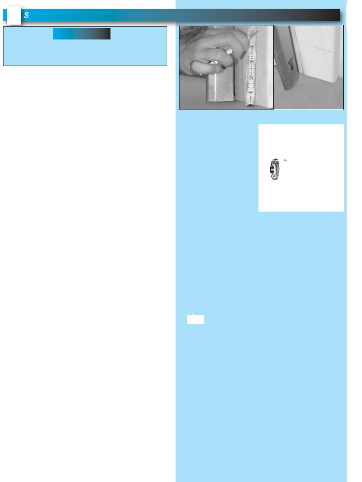
4 SAFE-T-BEAM® SYSTEM INSTALLATION
 WARNING
There should be no electrical power to the opener while installing Safe-T-Beam® wires. If you have plugged in the power cord—UNPLUG IT NOW!
NOTE: The opener will not close the door automatically unless the Safe-T-Beam® System is installed.
NOTE: For Sensors, screws, wire, and insulated staples locate items and Bag 8 from Box 3.
1.Mounting brackets.
•Mark both sides of garage door frame or wall no higher than 6" and no lower than 5" above floor
(Fig. 4-1).
•Hold bracket against door frame or wall.
–Check if brackets extend out from wall far enough, so tongue of bracket is beyond door, tracks or any door hardware.
–If not:
a)Mounting bracket extensions are available through an authorized Genie® Dealer.
b)Blocks of wood, etc. may be substituted for extensions.
•Locate top of bracket on your mark (Fig. 4-2).
•Fasten each with 2 screws (Fig. 4-2).
NOTE: Mounting brackets can be attached to the floor or concrete rim using concrete anchors (not provided) obey manufacturer’s instructions.
2.Mounting Safe-T-Beam® Source (Red LED) and Sensor (Green LED).
•If garage has only one garage door.
–Determine which side of garage receives most direct sunlight (Fig. 4-4).
–Red LED should always be on sunny side whenever possible (Fig. 4-4).
•For multiple doors.
–Preventing crossed signals is critical.
–Place source and sensor modules on adjacent doors facing in opposite directions (Fig. 4-4).
NOTE: To help prevent interference from sun, Safe-T-Beam® sensor with Green LED may be placed further away from the door opening, though extended no further out from the wall, where it will spend more time in shadow.
•Slide source/sensor onto tongue of bracket until it clicks into place (Fig. 4-3).
3a. Wiring (If NOT pre-wired).
•Route wire from Safe-T-Beam® sensors to power head using method shown in (Fig. 4-5a).
• Securely fasten wires to wall and ceiling as you go (Fig. 4-6 on next page).
– Use insulated staples.
– Staples should be snug only.
Insulated
Staple
FOR HELP-1.800.354.3643 OR WWW.GENIECOMPANY.COM
mark
FIG. 4-1 Mark door frame.
center of bracket
FIG. 4-2
Mounting brackets.
SUN
e |
lid |
s |
bracket |
tongue |
FIG. 4-3 Attach sensors to brackets.
RED |
GREEN |
GREEN |
RED RED |
GREEN |
LED |
LED |
LED |
LED LED |
LED |
ONE DOOR |
|
TWO DOOR |
|
|
GARAGE |
|
GARAGE |
|
|
GREEN |
RED RED |
GREEN GREEN |
RED |
|
LED |
LED LED |
LED |
LED |
LED |
THREE DOOR
GARAGE
FIG. 4-4 Safe-T-Beam® source and sensor locations.
Red
Source
Power
Head
 Green
Green
Sensor
6 5 4 3 2 1 or 6 5 4 3 2 1
Dashed Line = striped wire Solid Line = white wire
FIG. 4-5a Source and sensor wiring methods.
PN# 37026500123 |
02/26/2010 REV. 1 |
17 |
|
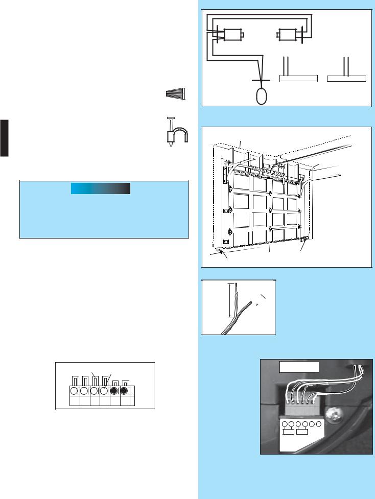
3b. Wiring (pre-wired).
•Route wire from wall to Safe-T-Beam® sensors
(Fig. 4-5b).
•Splice pre-wiring to shortened sensor wire, match wire pairs dash-to-dash (striped-to- striped) and plain-to-plain (white-to-white).
-Trim sensor wire to approximately one foot (1 ft) from sensor.
-Split and strip ends of sensor wires and
pre-wired wires (Fig. 4-7).
- Splice wires together with (provided) wire nuts.
• Route wire from ceiling to power head
(Fig. 4-5b).
•Securely fasten wires where they exit wall and ceiling as you go.
– Use insulated staples.
– Staples should be snug only.
 CAUTION
Staples which are too tight can cut or pinch wires. Cut or pinched wires can cause the Safe-T-Beam® System to stop working. When using the insulated staples, make sure you fasten them only as tightly as needed to hold the wire snugly.
4. Split and strip ends of sensor wires (Fig. 4-7).
NOTE: For rear cover locate Box 4.
5.Attach Safe-T-Beam® wire to power head wire terminal.
•Route Safe-T-Beam® wires through wire guide on power head.
–Insert wire into terminal holes and lightly press in the orange locking clips above each terminal hole. (You can use a pencil or small screwdriver to comfortably reach in and lightly press down locking clips.) Insert white wires to 'even' numbered terminal holes and striped wires into 'odd' terminal holes (Fig. 4-8).
Locking
Clips Terminal
Holes
6 5 4 3 2 1
–Confirm wire lock by lightly tugging on the wire. The wire should remain in the terminal hole.
•Do not install the white (lamp) cover at this time.
NOTE: Safe-T-Beam® alignment check must be performed following connection to electrical power (see page 19). DO NOT PLUG IN YET!
Wall
Red
Source
Ceiling
Power
Head
Wall
Green
Sensor
6 5 4 3 2 1 or 6 5 4 3 2 1
Dashed Line = striped wire Solid Line = white wire
FIG. 4-5b Pre-Wired source and sensor wiring methods.
Wire |
|
Insert Wire |
|
Into Connector |
|
|
|
Wire |
|
|
Use this |
|
|
wire routing |
|
|
if NOT pre-wired |
|
Invisible Light Beam |
Sensor |
|
|
|
Sensor |
Protection Area |
|
|
|
FIG. 4-6 Wire routing.
2" 

 1/2"
1/2"
FIG. 4-7 Splitting and stripping.
wire guide 
FIG. 4-8 |
6 |
5 |
4 |
3 |
2 |
1 |
|
|
|
|
+ – |
||
Insert wires. |
|
|
|
|
||
|
|
|
|
P |
B |
|
|
InfaredSensor |
|
|
|
||
(Power Head With Rear Cover Removed)
18 |
PN# 37026500123 |
02/26/2010 REV. 1 |
|
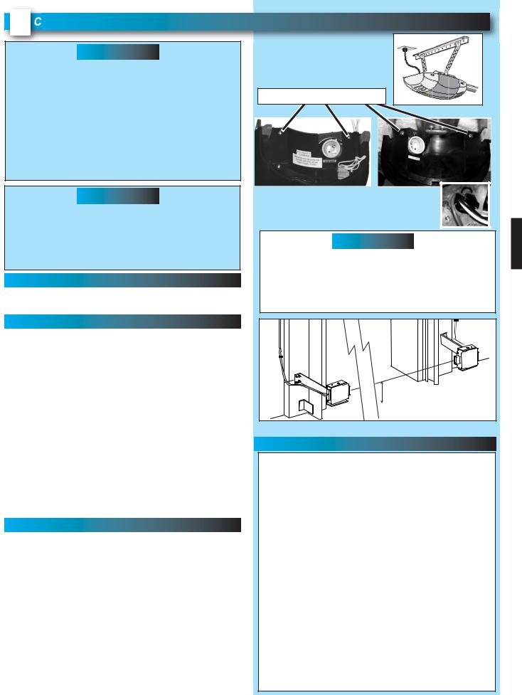
5 CONNECTING TO POWER
 WARNING
•To reduce the risk of electrical shock, this equipment has a grounded type plug that includes a third (grounding) pin. This plug will only fit a grounded type outlet. If you do not have a grounded outlet, contact a qualified licensed electrician to install one. DO NOT alter the plug in any way. The door opener must be properly grounded in order to prevent personal injury and damage to the components.
•DO NOT remove motor cover. All work performed on motor must be done by a trained door system technician.
 CAUTION
•Check local building codes to make sure that you are not required to have your garage door opener permanently wired, with circuit breaker protection. If building codes require door opener to be permanently wired have a qualified licensed electrician connect power with permanent wiring.
WITH GROUNDED PLUG:
Plug the opener into a properly grounded electrical outlet (Fig. 5-1).
WITH PERMANENT WIRING:
Instructions for Electrician.
•Remove power from circuit.
•Remove rear cover and motor cover.
–Remove four motor cover screws (Fig. 5-2).
•Remove existing power cord and strain relief from the 7/8" dia. hole and discard (Fig. 5-3).
•Connect permanent wiring to power head using 7/8" diameter hole.
–White to white/black to black/ground to green.
–Use only UL recognized wire nuts.
•Wires inside the power head must be at least 6" in length.
•Replace motor cover and rear cover and re-energize the circuit.
NOTE: The Genie Company is not responsible for charges resulting from work performed by an independent electrician.
WITH POWER SUPPLIED:
Check Safe-T-Beam® alignment (Fig. 5-4).
•Insure that no part of door or its hardware is in path between lenses of source and sensor.
•Insure that tops of lenses are between 5" - 6" above the floor (Fig. 5-4). The brackets are flexible, and can be adjusted slightly if needed.
•Adjust the Red LED transmitter by aiming the unit directly at the Green LED receiver. Use the adjustment screw located on the top of the transmitter housing to make adjustments.
•The Red LED transmitter will blink if there is a misalignment. When the LED units are aligned the Red LED will remain ON continuously.
•After the alignment is finished tighten the adjustment screws on both sensors.
FOR HELP-1.800.354.3643 OR WWW.GENIECOMPANY.COM
FIG. 5-1 Connect to power.
Motor Cover Screws
FIG. 5-2 Remove motor cover. (Electrican ONLY)
FIG. 5-3 Power cord strain relief.
 CAUTION
•Do NOT use an extension cord.
•Do NOT use a portable generator. This product is designed to operate using standard household current.
•Do NOT use alternate power supplies.
|
|
|
|
o |
m |
fl |
o |
o |
r |
|
|
|
fr |
r |
|||||
|
|
|
|
||||||
|
|
|
|
|
|||||
|
|
|
|
|
|
||||
6 |
" m |
ax |
om |
fl |
o |
o |
|
||
|
|
||||||||
|
|
|
|
||||||
|
|
in |
fr |
|
|
|
|
|
|
5" m |
|
|
|
|
|
|
|
||
FIG. 5-4 Check Safe-T-Beam® alignment. |
|||||||||
INFRARED PROTECTION FUNCTION
1.When the garage door is opening, its movement will not be influenced if the Safe-T-Beam® is obstructed.
2.If the Safe-T-Beam® is obstructed before the garage door fully closes, the door will not close.
3.When the garage door is closing, if Safe-T-Beam® is cut off by people or obstacle, the garage door will reverse automatically to its fully opened position. (Meanwhile, the opener light will keep blinking until door moves to its fully opened position.)
4.If the Safe-T-Beam® System fails, loses power, or is installed improperly, press and hold the Wall Control "open/close" button until the door reaches its fully closed position. The LED indicator light on the power head will be green and blink twice (Pattern: ☼☼ pause ☼☼ pause) to inform you to eliminate the problem first.
If you release the "open/close" button on the Wall Control during the closing movement the door will reverse automatically to its fully opened position.
PN# 37026500123 |
02/26/2010 REV. 1 |
19 |
|
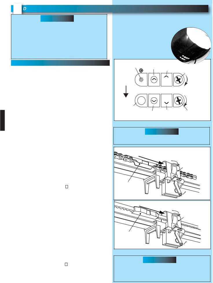
6 DOOR LIMITS
 WARNING
•Severe injury or death can result if the door closing force is set too high.
•Never increase the door closing force above the minimum required to move the door.
•Never adjust force to compensate for a sticking or binding door.
•Perform monthly CONTACT REVERSE TEST as described on page 22 and in Section 10.
SETTING & TESTING OPEN/CLOSE LIMITS
The OPEN (UP) and CLOSE (DOWN) door positions are controlled by making the adjustments on the panel located on the bottom of the power head. The adjustments that can be made are:
•Close Travel Limit,
•Open Travel Limit, Adjust Closing Force Adjust Opening Force
Transmitter Programming
A)ENGAGE CHAIN/BELT CONNECTOR TO CARRIAGE
1.Press and hold the "Close Travel Limit"  button until the chain or belt connector advances and engages to the Carriage Assembly (Fig. 6-2).
B)CLOSE TRAVEL LIMIT
1.Press and hold the "Close Travel Limit"  button until the door is fully closed.
2.You can quickly press and release the "Close Travel Limit"  button to move the door in small increments. You can also use the "Open Travel Limit"
  button to move the door slightly in the UP direction.
3.Door is fully closed when the bottom edge of door presses firmly onto the ground.
4.Once the door is in the desired position, press and hold the "Close SET Limit" SET button for 5 seconds. The LED indicator light will blink green once. This stores the closed position in memory.
C) OPEN TRAVEL LIMIT
1.Press and hold the "Open Travel Limit"  button to move the door to its fully opened position. This starts the opener moving in the UP direction.
2.Hold the "Open Travel Limit"  button until the door is in the fully opened position that you desire, then release this button.
3.You can quickly press and release the "Open Travel Limit"  button to move the door in small increments. You can also use the "Close Travel Limit"
  button to move the door slightly in the DOWN direction.
4.Once the door is in the desired position, press and hold the "Open SET Limit" SET button for 5 seconds. The LED indicator light will blink green twice. This stores the opened position in memory.
FOR HELP-1.800.354.3643 OR WWW.GENIECOMPANY.COM
Limit Controls location on power head.
NOTE: Set Close Travel Limit before setting Open Travel Limit for unit to operate normally.
Unless limits are being reset do not press set limit buttons.
LED |
Open |
Open |
|
|
|
Indicator Light |
Set Limit |
|
Up Force |
||
Travel Limit |
|
||||
|
|
Button |
OPEN Control |
||
|
|
|
|||
|
|
|
|
|
Adjustment |
To |
|
|
SET |
|
|
Garage Door |
|
|
|
|
|
|
|
|
|
|
|
|
LEARN MANUAL LIMIT |
FORCE |
|
||
|
|
|
SET |
|
|
Learn |
|
|
|
|
|
Code |
CODE |
Close |
Close |
CLOSE |
Down Force |
Button |
|
|
|
||
|
|
Travel Limit Set Limit |
|
Control |
|
|
|
|
Button |
|
Adjustment |
FIG. 6-1 Limit controls.
 CAUTION
Failure to verify the engagement of the belt/chain connector will result in damage to rail components.
Move |
|
|
|
|
in |
this |
direction |
Latch |
|
|
|
|||
|
|
Movement |
||
|
|
|
|
Carriage Assembly |
Chain Connector |
|
|
|
|
|
|
|
|
Latch |
|
|
|
|
Movement |
M |
|
|
|
|
ove |
|
|
|
|
in |
|
|
|
|
|
this |
direction |
Latch |
|
|
|
|
||
|
|
|
Movement |
|
Carriage Assembly
Belt Connector
Latch
Movement
FIG. 6-2 Engage Chain/Belt Connector to Carriage.
 CAUTION
Operation of the opener without the Chain or Belt Connector engaged to the Carriage Assembly will result in damage to rail components including the rail pulley.
20 |
PN# 37026500123 |
02/26/2010 REV. 1 |
|
CARRIAGE LOCK |
DOOR |
|
The Carriage Lock can be manually engaged or |
|
|
disengaged. |
|
|
• To disengage Carriage Lock |
|
|
– Pull handle downward opener power head. |
|
|
• To engage Carriage Lock |
|
|
– Pull handle towards door. |
|
|
|
UNLOCK |
LOCK |
|
TO RELEASE |
TO RECONNECT |
|
PULL TOWARD |
PULL TOWARD |
|
THE OPENER |
DOOR |
|
FIG. 6-3 Engage/Disengage Carriage Lock. |
|
KEYED EMERGENCY RELEASE (PURCHASED SEPARATELY)
Obtain standard emergency release kit and remove S-hook from the cable end that attaches to the opener carriage.
1.Attach the emergency release cable loop end to the opener carriage as shown (FIG 6-4).
Properly connecting the release cable to the carriage fitting will enable the correct carriage release action for the opener.
 WARNING
Improper connection of the emergency release cable to the opener carriage will result in a failure of the
emergency release.
FIG. 6-4 Emergency release cable to carriage.
2.Follow the remaining installation instructions for the standard emergency release kit.
3.Test for correct operation of emergency release kit.
Keyed Emergency Release Operation Instructions
•Place key in slot.
•Rotate and hold key while lifting garage door 1 to 2 inches.
•Release key and continue opening garage door.
NOTE: The next normal operation of the opener or fully closing garage door manually will re-engage the emergency release mechanism.
21
 Loading...