


 Loading...
Digital Energy
Operating Manual
Uninterruptible Power Supply
GE Consumer & Industrial SA
General Electric Company CH – 6595 Riazzino (Locarno) Switzerland
T +41 (0)91 / 850 51 51
F +41 (0)91 / 850 52 52 www.gepowerquality.com
gimagination at work

|
Digital Energy |
|
|
Model: |
VH Series UL |
Issued by: |
Product Document Department – Riazzino - CH |
Approved by |
R&D Department – Riazzino - CH |
Date of issue: |
22.06.2012 |
File name: |
GE_UPS_OPM_VHU_0K7_2K0_XUL_V040 |
Revision: |
4.0 |
Identification No. |
|
Up-dating |
|
|
Revision |
Concerns |
Date |
1.0 |
First release |
26.05.2009 |
2.0 |
Chapter 11 updated |
09.01.2012 |
3.0 |
New range 700-2000 VA |
27.03.2012 |
4.0 |
Updated Battery pack chapter, Power Cord specification & REPO |
22.06.2012 |
|
|
|
COPYRIGHT © 2012 by GE Consumer & Industrial SA
All rights reserved.
The information contained in this publication is intended solely for the purposes indicated.
The present publication and any other documentation supplied with the UPS system is not to be reproduced, either in part or in its entirety, without the prior written consent of GE.
The illustrations and plans describing the equipment are intended as general reference only and are not necessarily complete in every detail.
The content of this publication may be subject to modification without prior notice.
Modifications reserved |
Page 2/25 |
GE_UPS_OPM_VHU_0K7_2K0_XUL_V040.docx |
Operating Manual VH Series 700 - 1000 -1500 – 2000 VA UL |

 Digital Energy
Dear Customer,
We thank you for selecting our products and are pleased to count you amongst our very valued customers at GE.
We trust that the use of the VH Series Uninterruptible Power Supply system, developed and produced to the highest standards of quality, will give you complete satisfaction.
Please read carefully the Operating Manual, which contains all the necessary information and describes all you need to know about the use of the UPS.
Thank you for choosing GE !
Distributed by: |
Your service contact: |
g
GE Consumer & Industrial SA
General Electric Company
CH – 6595 Riazzino (Locarno)
Switzerland
Modifications reserved |
Page 3/25 |
GE_UPS_OPM_VHU_0K7_2K0_XUL_V040.docx |
Operating Manual VH Series 700 - 1000 -1500 – 2000 VA UL |

|
|
|
Digital Energy |
|
|
|
|
|
|
|
|
|
Contents |
|
1 |
IMPORTANT SAFETY INSTRUCTIONS ...................................................................................................................................... |
5 |
||
|
1.1 |
SAVE THESE INSTRUCTIONS............................................................................................................................................................................. |
5 |
|
|
1.2 |
SAFETY WARNINGS AND SYMBOLS .............................................................................................................................................................. |
5 |
|
|
1.3 |
SAFETY RULES.......................................................................................................................................................................................................... |
6 |
|
|
1.4 |
TRANSPORT / STORAGE ...................................................................................................................................................................................... |
6 |
|
|
1.5 |
FCC COMPLIANCE STATEMENT ....................................................................................................................................................................... |
6 |
|
2 |
INTRODUCTION ......................................................................................................................................................................... |
7 |
||
|
2.1 |
INTRODUCTION....................................................................................................................................................................................................... |
7 |
|
|
2.2 |
INTENDED USE ........................................................................................................................................................................................................ |
7 |
|
|
2.3 |
WARRANTY................................................................................................................................................................................................................ |
7 |
|
|
2.4 |
DIAGRAM.................................................................................................................................................................................................................... |
7 |
|
3 |
INSTALLATION............................................................................................................................................................................ |
8 |
||
|
3.1 |
PACKAGE CONTENTS ........................................................................................................................................................................................... |
8 |
|
|
3.2 |
INSTALLATION RULES .......................................................................................................................................................................................... |
8 |
|
|
3.3 |
INSTALLATION PREPARATIONS ....................................................................................................................................................................... |
9 |
|
|
|
3.3.1 |
Vertical installation - preparations ................................................................................................................................................................. |
9 |
|
|
3.3.2 |
Rackmount installation - preparations ...................................................................................................................................................... |
10 |
|
3.4 |
REAR PANEL........................................................................................................................................................................................................... |
11 |
|
|
3.5 |
INSTALLATION OF A BATTERY EXTENSION PACK................................................................................................................................ |
13 |
|
|
3.6 |
CONNECTIONS...................................................................................................................................................................................................... |
14 |
|
|
|
3.6.1 |
Connecting interface devices ......................................................................................................................................................................... |
14 |
|
|
3.6.2 |
Connecting power and load ........................................................................................................................................................................... |
14 |
4 |
OPERATION |
............................................................................................................................................................................... |
15 |
|
|
4.1 |
OPERATING .............................................................................................................................................................................................PANEL |
15 |
|
|
4.2 |
START ................................................................................................................................................................................................................-UP |
16 |
|
|
|
4.2.1 ................................................................................................................................................................................. |
Start - up, mains available |
16 |
|
|
4.2.2 ......................................................................................................................................................................... |
Start - up, mains not available |
16 |
|
4.3 |
USE: NORMAL .............................................................................................................................................................................OPERATION |
16 |
|
|
|
4.3.1 ......................................................................................................................................................................... |
Normal operation conditions |
16 |
|
|
4.3.2 .............................................................................................................................................................................................. |
No - load shutdown |
16 |
|
|
4.3.3 ................................................................................................................................................................................................. |
Output frequency |
16 |
|
|
4.3.4 .......................................................................................................................................................................................................... |
Switching off |
16 |
|
4.4 |
USE: STATUS .................................................................................................................................................AND ALARM INDICATIONS |
17 |
|
|
|
4.4.1 .................................................................................................................................................................................................................... |
Standby |
18 |
|
|
4.4.2 ................................................................................................................................................................................................ |
Normal operation |
18 |
|
|
4.4.3 ............................................................................................................................................................................................................... |
On bypass |
18 |
|
|
4.4.4 ............................................................................................................................................................................................................... |
On battery |
18 |
|
|
4.4.5 ........................................................................................................................................................................... |
Battery low (end of runtime) |
18 |
|
|
4.4.6 ............................................................................................................................................................................................. |
Bypass out of limits |
18 |
|
|
4.4.7 .................................................................................................................................................................................................................. |
Overload |
18 |
|
|
4.4.8 ............................................................................................................................................................................................................. |
Battery bad |
19 |
|
|
4.4.9 ........................................................................................................................................................................................................ |
General alarm |
19 |
|
|
4.4.10 .............................................................................................................................................................................................. |
Shutdown pending |
19 |
|
|
4.4.11 .................................................................................................................................................................................................... |
Startup pending |
19 |
|
|
4.4.12 .......................................................................................................................................................................... |
P - N (Phase - Neutral) reversal |
19 |
|
|
4.4.13 ............................................................................................................................................................... |
REPO (Remote External Power Off) |
19 |
|
4.5 |
USE: SETUP ...............................................................................................................................................................................................MODE |
20 |
|
|
4.6 |
BATTERY ..................................................................................................................................................................................MANAGEMENT |
21 |
|
5 |
COMMUNICATION ................................................................................................................................................................... |
22 |
||
|
5.1 |
USB PORT ................................................................................................................................................................................................................ |
22 |
|
|
5.2 |
RJ11 ..............................................................................................................................................................................................................PORT |
22 |
|
|
5.3 |
USB / ..............................................................................................................................RS232 / RELAY INTERFACE CARD (OPTION) |
22 |
|
|
5.4 |
SNMP ................................................................................................................................................/ WEB INTERFACE CARD (OPTION) |
22 |
|
6 |
MAINTENANCE......................................................................................................................................................................... |
23 |
||
|
6.1 |
SAFETY...................................................................................................................................................................................................................... |
23 |
|
|
6.2 |
GENERAL ................................................................................................................................................................................................................. |
23 |
|
|
6.3 |
RECYCLING ..........................................................................................................................THE UPS AT THE END OF SERVICE LIFE |
23 |
|
|
6.4 |
BATTERIES............................................................................................................................................................................................................... |
23 |
|
7 |
TROUBLESHOOTING................................................................................................................................................................ |
24 |
||
8 |
SPECIFICATIONS ...................................................................................................................................................................... |
25 |
||
Modifications reserved |
Page 4/25 |
GE_UPS_OPM_VHU_0K7_2K0_XUL_V040.docx |
Operating Manual VH Series 700 - 1000 -1500 – 2000 VA UL |

 Digital Energy
1 IMPORTANT SAFETY INSTRUCTIONS
1.1SAVE THESE INSTRUCTIONS
This manual contains important instructions that should be followed during installation and maintenance of the UPS. It also gives all necessary information about the correct use of the UPS. Before attempting to install and start up the UPS, carefully read this manual. Keep this manual next to the unit for future references.
Full understanding of and compliance with the safety instructions and warnings contained in this manual are the
ONLY CONDITIONS
to avoid any dangerous situation during installation, operation and maintenance work, and to preserve the maximum reliability of the UPS system.
GE refuses any responsibility in case of non-observance, unauthorized alterations or improper use of the delivered UPS.
The instructions in this manual are for UPS models VH Series 700, VH Series 1000, VH Series 1500, and VH Series 2000. Check your model number by looking at the rear panel of your UPS. Any difference in instructions is clearly indicated in the text, for instance ‘(VH Series 1000)’.
The UPS is not suitable for computer room application as per the standard NFPA75.
While every care has been taken to ensure the completeness and accuracy of this manual, GE accepts no responsibility or liability for any loss or damage resulting from the use of the information contained in this document.
This document shall not be copied nor reproduced without the permission of GE.
Due to technical improvements, some of the information contained in this manual may be changed without notice.
1.2SAFETY WARNINGS AND SYMBOLS
The text of this manual contains warnings to avoid risk to persons, to avoid damages to the UPS system and the supplied critical loads. Do not proceed beyond these warnings if you do not fully understand or are not able to meet the mentioned conditions. The non-observance of the warnings reminding hazardous situations could result in human injury and equipment damage.
Please pay attention to the meaning of the following warnings and symbols.
Safety warnings
WARNING! Refers to procedures or operations which, when not correctly performed, could cause personal injury or serious damage to the system.
CAUTION The product may be in danger: when procedures or operations are not correctly performed, damage to the product may be the result.
NOTE Warns the user about important operations or procedures described in this manual.
Safety Symbols
DANGER OF ELECTRICALLY LIVE PARTS
Related to all situations with potentially hazardous voltage.
SAFETY WARNING
This symbol is used for Warnings, Cautions and Notes.
Modifications reserved |
Page 5/25 |
GE_UPS_OPM_VHU_0K7_2K0_XUL_V040.docx |
Operating Manual VH Series 700 - 1000 -1500 – 2000 VA UL |

 Digital Energy
1.3SAFETY RULES
CAUTION! RISK OF ELECTRIC SHOCK
The UPS has an internal battery supply with a nominal voltage of 72Vdc. The appliance outlets may be electrically live, even when the UPS is disconnected from the mains.
The UPS contains potentially hazardous voltages. Do not open the unit, there are no user serviceable parts inside.
CAUTION
There may be damage to the equipment if procedures and practices are not strictly observed and followed.
NOTE
Do not attempt to service the UPS unless you have had proper training. Refer all maintenance and servicing to properly qualified, skilled and competent service personnel.
Qualified, skilled personnel are persons who (because of their training, experience, and position as well as their knowledge of appropriate standards, regulations, health and safety requirements and working conditions) are authorised to be responsible for the safety of the equipment, at all times whilst carrying out their normal duties and are therefore aware of, and can report, possible hazards (observe IEC 60364 and national wiring regulations and accident prevention rules).
1.4TRANSPORT / STORAGE
WARNING!
Please consider the weight of the UPS. Lift the box with the help of a second person; never try to lift it by yourself!
No liability can be accepted for any transport damage when the equipment is shipped in non-original packaging.
Store the UPS in a dry location with the batteries in a fully charged state. Storage temperature must be within -4 and 122 F (-20 and +50 C). If the unit is stored for a period exceeding 3 months, optimal battery lifetime is obtained if the storage temperature does not exceed 86 F (30 C).
If the unit is stored for an extended period of time, the batteries must be recharged periodically. Connect the unit to a wall outlet and recharge the batteries for 24 hours:
-if the storage temperature is within -4 and 86 F (-20 and +30°C): every 12 months,
-if the storage temperature is within -4 and 122 F (-20 and +50°C): every 3 months.
CAUTION
In case of storage, pay attention to:
1.5FCC COMPLIANCE STATEMENT
Note: This equipment has been tested and found to comply with the limits for a Class B digital device, pursuant to Part 15 of the FCC Rules. These limits are designed to provide reasonable protection against harmful interference when the equipment is operated in a residential environment. This equipment generates, uses and can radiate radio frequency energy and, if not installed and used in accordance with the instruction manual, may cause harmful interference to radio communications.
Modifications not expressly approved by the manufacturer could void the user’s authority to operate the equipment under
FCC rules.
Modifications reserved |
Page 6/25 |
GE_UPS_OPM_VHU_0K7_2K0_XUL_V040.docx |
Operating Manual VH Series 700 - 1000 -1500 – 2000 VA UL |
 Digital Energy
2 INTRODUCTION
2.1INTRODUCTION
The GE (General Electric) Digital Energy VH Series UPS, a truly on-line uninterruptible power supply, protects your equipment from all forms of power interference, including complete power failures.
2.2INTENDED USE
Uninterruptible Power Supplies (UPS) are designed to protect sensitive electronic equipment such as computers and telecommunications equipment.
CAUTION
DO NOT plug household appliances such as electric heaters, toasters or vacuum cleaners into the UPS. The UPS output is intended to be used only for electronic loads such as computers and telecommunications equipment.
The technical data as well as information concerning connecting requirements can be found on the rating label and in this document and shall be strictly observed.
2.3WARRANTY
GE, operating through its authorised agents, warrants that the standard products will be free of defects in materials and workmanship for a period as per contract specifications, starting from the date of the invoice.
NOTE
This warranty does not cover failures of the product which result from incorrect installation, misuse, alterations by persons other than authorized agents, or abnormal operating conditions.
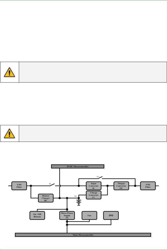
2.4DIAGRAM
Fig. 2.4: Diagram
Modifications reserved |
Page 7/25 |
GE_UPS_OPM_VHU_0K7_2K0_XUL_V040.docx |
Operating Manual VH Series 700 - 1000 -1500 – 2000 VA UL |
 Digital Energy
3 INSTALLATION
3.1PACKAGE CONTENTS
The UPS shipping box contains:
VH Series UPS
4 plastic support parts
Mounting set
1 plastic front panel
2 plastic plugs
2 mounting brackets and screws
1 USB cable
1 CD ROM with UPS monitoring software (see 5.3) and its manual
This manual
REPO Connector (see 4.4.13)
Inspect the UPS for damage after unpacking. If any damage is present please immediately notify the carrier and place of purchase.
WARNING! In case of recognizable damage:
DO NOT connect any voltage to the unit
DO NOT put the unit into operation
Condensation may occur if the UPS system is moved directly from a cold to a warm environment. The UPS system must be absolutely dry before being installed. Please allow an acclimatization time of at least two hours.
3.2INSTALLATION RULES
NOTE
Before making any connection and switching on the VH Series UPS, please check the following conditions:
Your mains supply is 120 Volts and 50/60 Hz.
The total power demand of the connected equipment does not exceed the rated output power of the VH Series UPS (section 8 for the ratings).
The UPS is intended to be used in normal domestic and office situations.
The UPS must be powered from a single phase grounded wall outlet. Do not use extension cords.
Avoid locations that are excessively humid, near water, near heat sources or in direct sunlight.
The ambient temperature should not exceed 104 F (40 C). Optimal battery lifetime is obtained if the ambient temperature does not exceed 86 F (30 C).
It is important that ventilation air can move freely around and through the unit. Do not block the air vents.
Do not plug appliances such as electric heaters, toasters and vacuum cleaners into the UPS. The UPS output can be used only for electronic loads such as computers and telecommunications equipment.
Be careful when connecting laser printers: be sure that the demanded power does not exceed the capacity of the UPS.
The sum of the leakage currents of the UPS and the connected loads should not exceed 3.5mA.
Connect only to short circuit and over-current protection branch circuit rated in accordance with the National Electric Code, ANSI/NFPA 70, see following table:
UPS model |
Branch protection |
VH 700 |
20A |
VH 1000 |
20A |
UPS model |
Branch protection |
VH 1500 |
20A |
VH 2000 |
20A |
CAUTION
To reduce risk of fire, connect the UPS only to a circuit provided with fuse values according to the above
Modifications reserved |
Page 8/25 |
GE_UPS_OPM_VHU_0K7_2K0_XUL_V040.docx |
Operating Manual VH Series 700 - 1000 -1500 – 2000 VA UL |
Loading...