


 Loading...
Basic Installation and User’s Guide for the Millennium II Controller J85501P-1
Product Manual
Select Code 167-792-181
Comcode 108994645
Issue 3
January 2008
Notice:
The information, specifications, and procedures in this manual are subject to change without notice. Lineage Power assumes no responsibility for any errors that may appear in this document.
© 2008 Lineage Power
All International Rights Reserved
Printed in U.S.A.
Basic Installation and User’s Guide for the Millennium II Controller
Table of Contents |
|
1 Introduction.................................................................................................................... |
4 |
Millennium II.................................................................................................................. |
4 |
Customer Service Contacts............................................................................................. |
5 |
2 Product Description....................................................................................................... |
6 |
Overview......................................................................................................................... |
6 |
Feature Summary............................................................................................................ |
6 |
General Specifications .................................................................................................. |
11 |
Hardware....................................................................................................................... |
12 |
3 Safety............................................................................................................................. |
15 |
Safety Statements.......................................................................................................... |
15 |
Warning Statements and Safety Symbols..................................................................... |
17 |
Precautions.................................................................................................................... |
18 |
Special Installation Notes ............................................................................................. |
19 |
4 New Installations.......................................................................................................... |
21 |
Controller Connections................................................................................................. |
23 |
Installing Circuit Packs................................................................................................. |
24 |
Thermal Probes............................................................................................................. |
28 |
USB Interface................................................................................................................ |
29 |
Wiring Alarm Outputs .................................................................................................. |
29 |
Wiring Alarm and Control Inputs................................................................................. |
32 |
Fuses ............................................................................................................................. |
35 |
Front Panel Display....................................................................................................... |
35 |
Controller Defaults........................................................................................................ |
39 |
Controller Display Menu Maps .................................................................................... |
46 |
5 Acceptance Testing ...................................................................................................... |
58 |
Introduction................................................................................................................... |
58 |
Tools and Test Equipment ............................................................................................ |
58 |
Test Precautions............................................................................................................ |
58 |
Test Sequences.............................................................................................................. |
59 |
6 Controller Retrofits ..................................................................................................... |
67 |
Millennium Basic Controller Retrofit........................................................................... |
67 |
Millennium Intelligent Controller Retrofit ................................................................... |
85 |
7 Troubleshooting ......................................................................................................... |
104 |
Controller Circuit Pack ............................................................................................... |
104 |
Option Cards............................................................................................................... |
104 |
Controller Alarm Descriptions.................................................................................... |
104 |
Clear Events................................................................................................................ |
110 |
Uninstall Devices........................................................................................................ |
111 |
8 Spare Parts ................................................................................................................. |
112 |
9 Product Warranty...................................................................................................... |
113 |
Revision History............................................................................................................ |
115 |
Issue 3 January 2008 |
3 |
Basic Installation and User’s Guide for the Millennium II Controller
1 Introduction
Millennium II
The J85501P-1 Galaxy Millennium II controller is the next generation full-featured power system controller from Lineage Power. It provides control, monitoring, and alarm monitoring functions over a multi-drop serial interface that interconnects system rectifiers, converters, Bay Interface Cards (BICs), and other serial devices. It utilizes robust RS-485 serial busses that support the Galaxy Protocol (GP) to communicate to these devices. The Millennium II has a plethora of I/O and monitoring options. It can monitor and control battery plants containing up to 64 Galaxy serial rectifiers, up to 16 serial converters, and up to 32 BICs. A maximum combination of 85 GP nodes can be directly managed on the rectifier serial bus. The Millennium II performs many functions described more thoroughly in following sections. Following is a high level view.
•Alarm Detection, Identification, and Reporting
•System and Component Status
•System and Feature Configuration
•System Alarm Thresholds
•Battery Management (Slope Thermal Compensation/Recharge Current Limit)
•Battery discharge testing
•Reserve Time Prediction
•Selective high/low voltage shutdown
•Float/Boost Mode Control
•Low Voltage Disconnect Management
•Remote Access Control And Multiple Level Password Security
•Control and Operations
•History
•Statistics
This controller replaces the existing +24V and -48V versions of the Millennium controller with a single unit. While becoming easier to use, the Millennium II adds additional functionality to the comprehensive feature set now provided by the existing Millennium. The Millennium II is Lineage Power’s new flagship controller product. The separate Independent (Basic), Intelligent, and network interface circuit packs of the existing Millennium controller have been integrated into a single standard board offering with the Millennium II. This eliminates the need to manage multiple boards for features as well as plant voltage. Intelligent functionality with remote 10/100 Base-T network access capability to display power system operating status and available information via the world wide web (internet) or your enterprise network (intranet) using standard browsers such as Microsoft Internet Explorer® or Netscape® Navigator is now the standard offering.
Issue 3 January 2008 |
4 |
Basic Installation and User’s Guide for the Millennium II Controller
Not only are the software features of the Millennium all contained in the Millennium II, the new controller is physically backwards compatible for field upgrades and replacements. The Millennium II can also be used as an upgrade to the door mounted Galaxy Vector controller When performed, this installation adds newer and more available technologies to the power system. The old Millennium chassis is replaced with the new Millennium II chassis shown in the figure following. All existing and future GPS cabinet systems remain supported by the Millennium II.
Figure 1-1:Galaxy Millennium II Controller
Customer Service Contacts
Customer Service, Technical Support, and Warranty Service
For customers in the United States, Canada, Puerto Rico, and the US Virgin Islands, call 1-800-THE-1PWR (1-800-843-1797). This number is staffed from 7:00 am to 5:00 pm Central Time (zone 6), Monday through Friday, on normal business days. At other times this number is still available, but for emergencies only. Services provided through this contact include initiating the spare parts procurement process, ordering documents, product warranty administration, and providing other product and service information.
For other customers worldwide the 800 number may be accessed after first dialing the AT&T Direct country code for the country where the call is originating, or you may contact your local field support center or your sales representative to discuss your specific needs.
Customer Training
Lineage Power offers customer training on many Power Systems products. For information call 1-972-284-2163. This number is answered from 8:00 a.m. until 4:30 p.m., Central Time Zone (Zone 6), Monday through Friday.
On-Line Power Systems Product Manuals and Software
Power Systems on-line product manuals and software are available on-line. Software includes Easy View and SNMP MIB.
Issue 3 January 2008 |
5 |

Basic Installation and User’s Guide for the Millennium II Controller
2 Product Description
Overview
The Millennium II has been designed to be a complete power system monitor and controller with a variety of alarming and remote access capabilities that complies with all relevant regulatory requirements, respectively. It is the nerve center of the battery plant that utilizes serial monitored and controlled rectifiers, converters, and system peripherals. It monitors and controls the plant rectifiers, distribution, and batteries. It can also monitor and control peripheral power equipment, including standby generators, converter plants, and inverters.
The Millennium II monitors and control battery plants containing up to 64 Galaxy serial rectifiers, up to 16 serial converters, and up to 32 Bay Interface Cards (BICs). A maximum combination of 85 GP nodes can be directly managed on the rectifier RS485 serial bus. The following table contains the Lineage Power rectifiers that can interface with the Galaxy Millennium II:
Table 2-A: Rectifiers That May Be Used With Millennium II
Model |
Vdc |
Current |
570A |
-48V |
100A |
595A, 595B, |
-48V |
200A/220A |
595C, 595LTA, |
|
|
595LTB |
|
|
596A / 596D |
-48V |
50A / 100A |
|
|
|
596B |
+24V |
100A / 125A |
596F |
+24V |
100A |
|
|
|
NP |
+24V / - |
24A – 50A |
|
48V |
|
CPS6000 QS86X |
-48V |
7.5A – 50A |
|
|
|
AC3000 |
-48V |
60A |
Feature Summary
The Millennium II has combined and enhanced its Millennium predecessor’s Basic, Intelligent, and Network functionality into its standard offering. This controller unit supports Lineage Power‘s most extensive controller feature set. Following is a summary of the features available in the Millennium II.
Issue 3 January 2008 |
6 |
Basic Installation and User’s Guide for the Millennium II Controller
Standard System Features
Monitoring and control of up to |
• Maximum of 64 serial switchmode rectifiers |
|
85 RS485 serial connected |
• Maximum of 32 Bay Interface Cards (BICs) |
|
devices |
• Maximum of 16 serial converters |
|
|
|
|
Alarms |
• Standard and custom User Defined system |
|
|
|
alarms |
|
• Alarm test |
|
|
• Alarm cut-off |
|
|
• Multiple-level alarm severity: Critical, Major, |
|
|
|
Minor, Warning, and Record-Only |
Rectifiers |
• Automatic rectifier restart |
|
|
• Reserve engine transfer |
|
|
• High Voltage Shutdown |
|
|
• Energy management |
|
|
• Remote rectifier (on/off) control |
|
|
• Automatic rectifier sequence control |
|
|
• N + X redundancy check |
|
|
• Digital voltage regulation and rectifier load |
|
|
|
share |
Contactor/Disconnect Control |
• |
Low Voltage Load |
|
• |
Low Voltage Battery |
Interfaces |
• |
Enhanced Front Panel Display |
|
• |
Local PC Port |
|
• |
Modem |
|
• |
LAN (Gateway Card) |
|
• |
X.25/TL1 |
Peripheral Monitoring and |
• |
Up to 512 monitoring channels |
Control |
• |
On board generic voltage channel |
|
• On board 4-20mA transducer interface |
|
Maintenance Tools |
• |
User Programmable Alarms |
|
• |
History |
|
• |
Statistics |
|
• |
Diagnostics |
|
• |
Derived Channels |
|
• |
Inventory Management |
|
• |
Configuration Backup/Restore |
Memory |
• |
Non-Volatile |
|
• |
Battery Backed |
|
• Remote and Local Software Upgrade |
|
Issue 3 January 2008 |
7 |
Basic Installation and User’s Guide for the Millennium II Controller
Enhanced Front Panel User Interface
Cabinet door mounted |
• |
Front access without opening the cabinet door |
LCD |
• |
8-line by 40-character (240 x 64) backlit |
|
|
display with digital contrast adjust |
Menu Driven User Interface |
• |
Re-designed user friendly menu driven LCD |
|
|
with similar push-button membrane switch |
|
|
interface |
|
• Menu structure similar to other Lineage Power |
|
|
|
controllers |
Audible Alarm Buzzer |
• |
Integrated on display assembly |
|
• |
May be Enabled/Disabled |
LEDs |
• 12 individual user configurable status LEDs: |
|
|
Critical, Major, Minor, Normal, AC System, |
|
|
Battery, Controller, Distribution, Rectifier, |
|
|
Remote Modules, Modem, and Battery On |
|
|
Discharge |
|
|
|
|
Test Jacks |
• Used to verify displayed system bus voltage |
|
Local Port |
• |
DB-9 RS232 system port for local terminal |
|
|
access or event log printing |
|
• ANSI T1.317 serial access |
|
|
• EasyView Windows-based software for |
|
|
|
configuration and reporting |
|
• Ground referenced |
|
Compatibility |
• |
Backwards compatible to existing Millennium |
Remote Access And Features
Integrated 10/100Base-T |
• |
Supports TCP/IP Version 5, SNMP Version |
Ethernet Network capability |
|
2c, SMTP, TL1, DHCP, Telnet, FTP |
|
• Standard and custom web pages for standard |
|
|
|
browsers (HTTP) |
|
• Compatible to Galaxy Manager |
|
|
• Standard shielded RJ-45 interface referenced |
|
|
|
to chassis |
Optional Modem access |
• |
Remote access via internal BSM5 Modem |
|
|
option (56k bps Modem) |
|
• Remote access capability via external Modem |
|
|
• |
Callback security |
Issue 3 January 2008 |
8 |
Basic Installation and User’s Guide for the Millennium II Controller
Optional BSW Dataswitch |
• |
Connections to 3 standard RS232 devices for |
|
|
pass-through and alarm management |
|
• BSN extension to provide 3 additional RS232 |
|
|
|
serial connections |
TL1 |
• |
Configurable RS-232/485 port for remote via |
|
|
TL1/X.25 |
Easy View PC User Interface |
• |
Windows-based software, for configuration |
|
• |
and reporting through local terminal or |
|
Modem connections |
|
Security |
• |
Multiple password-protected security levels |
|
• |
Dip Switches |
|
• Enhanced Security Features enable or disable |
|
|
|
many controller features |
Battery Management
Slope Thermal Compensation |
• High temperature compensation |
|
(STC) |
• Low temperature compensation |
|
|
• Step temperature |
|
|
• STC Enable/Disable |
|
|
• Low temperature Enable/Disable |
|
|
• |
mV/°C adjustments |
Recharge Current Limit |
• Control rechargerate for batteries |
|
Reserve Time Prediction |
• Supports a variety of batteries |
|
|
• Use configurable Low Reserve Time Alarm |
|
|
• Integrated “At Rate Calculator” for estimation |
|
|
|
purposes |
Battery Discharge Testing |
• |
Manual |
|
• |
Periodic |
|
• Plant Battery Test (PBT) input driven |
|
|
• Battery Discharge trace data |
|
Float/Boost Mode Control |
• Manual Timed BoostLocally T1.317 and |
|
|
|
remotely initiated |
|
• External Timed Boost |
|
|
• Battery Thermal Protect module Boost (BTP) |
|
|
• Auto Boost terminated by time or current |
|
|
• Manual front panel Boost |
|
Temperature Disconnect |
• Programmable high temperature |
|
Emergency Power Off |
• User programmable |
|
Issue 3 January 2008 |
9 |
Basic Installation and User’s Guide for the Millennium II Controller
Integrated Monitoring Inputs/Outputs
System |
Voltage and Current monitoring |
System Shunts |
• Maximum of 2 (more with BICs and RPMs) |
|
• Battery or Load |
|
• Battery or Return Side |
4-20 mA |
• Single channel |
|
• Input |
0-5 Vdc |
• Single Channel |
|
• Input |
|
• Selectable resistors for: 5, 30 and 60 Vdc |
|
ranges |
Temperature Probe |
• 4 Channels |
|
• 1 – 10/30k Thermal Probe Inputs |
|
• 3 – 10k Thermal Probe Inputs |
Binary Inputs |
• 22 Inputs |
|
• Engine signal inputs |
|
• Battery test inputs |
|
• External Float/Boost control |
|
• 2 User programmable |
Remote Peripheral Monitoring |
• Integrated serial bus |
|
• Maximum 300 M serial bus |
|
• 512 channels |
|
• Transducer interface |
|
• Battery, Shunt monitoring |
|
• Channels can be programmed for custom |
|
alarms |
Integrated Outputs
Traditional Office Alarms |
19 Form C alarm outputs |
|
2 User programmable relay outputs |
Alarm Battery Supply |
• 1.3A Fused |
Issue 3 January 2008 |
10 |
Basic Installation and User’s Guide for the Millennium II Controller
General Specifications
Basic Millennium II specifications are summarized in table 2-B. Consult service center for other details.
Table 2-B: General Millennium II Controller Specifications
General |
Specifications |
Input Voltage Range |
±24 Vdc, -48 Vdc (Range: 18-60V) |
Maximum Input Power |
36W depending upon options |
Operating Temperature Range |
-40 to 75 °C (-40 to 167 °F) |
Storage Temperature Range |
-40 to 85 °C (-40 to 185 °F) |
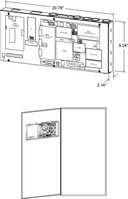
Physical Specifications |
9.24 in. H, 20.76 in. W, 2.14 in. D |
Display |
8-line by 40-character backlit LCD |
Cabinet Mounting Requirements |
Door mounted |
|
Input/Outputs |
Specifications |
|
Form C Alarm Output Contact Ratings |
60VDC at 0.5A |
|
Plant Voltage Measurement |
|
|
Accuracy |
|
|
0 to 50 °C (±.05% of full scale + 1 |
48V Systems: ±40 mV |
|
count) |
24V Systems: ±25 mV |
|
-40 to 85 °C (±0.1% of full scale + 1 |
48V Systems: ±70 mV |
|
24V Systems: ±40 mV |
|
|
count) |
0.01V |
|
Resolution |
|
|
Plant Current Measurement (Up to 2 |
|
|
shunts) |
0 to +50 °C : ±0.5% of full scale |
|
Accuracy |
-40 to +85 °C: ±1.25% of full scale |
|
Resolution |
1A |
|
|
|
|
Temperature Measurement |
|
|
Accuracy |
|
|
Thermistor temperature |
-5 to +55 °C: ±2°C |
|
|
-40 to +85 °C: ±3°C |
|
One-Wire Serial probes |
-5 to +55 °C: ±1°C (next release) |
|
|
-40 to +85 °C: ±3°C |
|
Resolution |
0.1°C |
|
4-20mA Input Monitor |
|
|
Accuracy |
±100µA |
|
Resolution |
±10.0µA |
|
General (0-5V) Input |
|
|
Accuracy |
0 to +50 °C: ±0.5% of full scale |
Issue 3 January 2008 |
11 |
Basic Installation and User’s Guide for the Millennium II Controller
|
-40 to +85 °C: ±1.0% of full scale |
Resolution |
0.01VDC |
Safety And Standards |
Specifications |
Electrostatic Discharge |
IEC 801-2 level 2, 4, 5 |
Radiated Emissions |
FCC Class B, CISPR 22 level B |
Safety |
UL Unlisted Component as Part of GPS Power |
|
System |
NEBs |
Level 3 Tested and Complaint with Galaxy Power |
|
Systems |
It should also be noted that the Millennium II is suitable for use in power plants with or without batteries. In batteryless plants, the loss of ac power causes an immediate loss of dc power to the controller and the activation of all office alarm relays. When ac power is restored, plant rectifiers will return to their last specified voltage set point, and the controller will automatically return to its last configuration.
Hardware
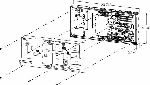
Chassis
The Galaxy Millennium II, like its Millennium predecessor, is low-profile enclosure mounted on the inside front cabinet door of a Galaxy Power System (GPS) plant. See Figure 2-1, and 2-2. This arrangement occupies no space within the frame mounting racks, thus allowing additional room for other plant equipment. The unit is pre-installed in the factory for all applicable GPS configurations. However, it has been designed to be backwards compatible to existing Millennium to allow field replacements or upgrades. It is composed of two main components: a rust resistant metal enclosure and a clear plastic cover. The metal enclosure interfaces with the cabinet door and provides appropriate cable routing entrances to the circuit pack it secures. A maintenance friendly clear plastic cover is used to protect the enclosed circuit packs. This cover also provides clear and quick visibility to individual circuit pack alarm status indicators and all wiring connections without removing a cover allowing quick board integrity and connectivity checks without removing cover.
Issue 3 January 2008 |
12 |
Basic Installation and User’s Guide for the Millennium II Controller
Figure 2-1: Controller Dimensions
Figure 2-2: Millennium Mounted on Cabinet Door
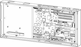
Controller Circuit Packs
MCR1 and MCR2
The core of the Galaxy Millennium II controller consists of a matched pair of surface mount technology circuit packs, MCR1 and MCR2. These circuit cards are attached and secured together at the factory. See Figure 2-3. The MCR1 is the larger of the two boards and contains all the external input/output interfaces, local and remote user interface circuitry, measurement circuits, real time clock, wide input range power converter, and connections for the MCR2. The MCR2 contains the main 32-Bit 66MHz microprocessor
Issue 3 January 2008 |
13 |

Basic Installation and User’s Guide for the Millennium II Controller
with 16Mbytes of Flash memory and 8Mbytes of RAM. It also contains the hardware for the Ethernet control. Factory calibration values for the analog circuits located on the MCR1 are stored in memory on the MCR2.
Figure 2-3: MCR1 and MCR2 Boards
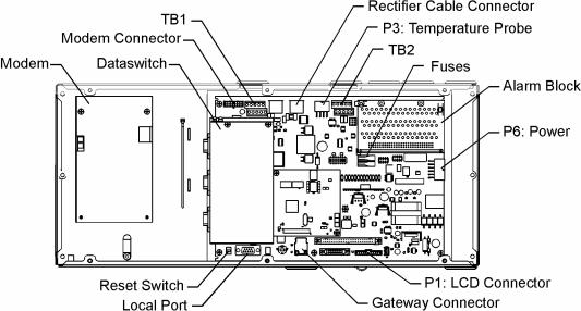
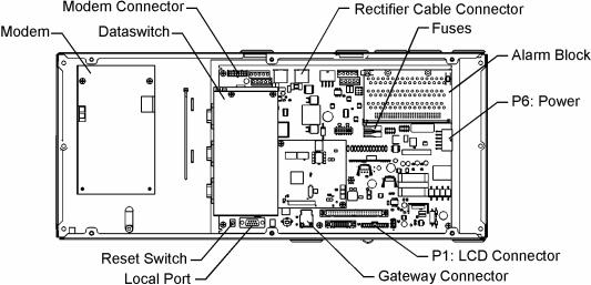
Figure 2-4: Millennium II Primary Interfaces
Figure 2-4 illustrates all of the primary interfaces located on the MCR1 for the Millennium II controller.
Issue 3 January 2008 |
14 |
Basic Installation and User’s Guide for the Millennium II Controller
3 Safety
Safety Statements
Please read and follow all safety instructions and warnings before installing, maintaining, or repairing the Millennium II controller:
•The CE Mark demonstrates compliance with the European Union Council Directives for Low Voltage and EMC.
•The Millennium II platform is Underwriters Laboratories (UL) recognized per Subject Letter 1801, DC Power Distribution Centers for Telecommunications Equipment.
•Install only in restricted access areas (dedicated equipment rooms, equipment closets, or the like) in accordance with articles 110-16, 110-17, and 110-18 of the U.S. National Electric Code (NEC), ANSI/NFPA No. 70, and pursuant to applicable local codes.
•This equipment is to be used in controlled environments (an area where the humidity is maintained at levels that cannot cause condensation on the equipment, the contaminating dust is controlled, and the steady-state ambient temperature is within the range specified).
•This equipment has been evaluated for continuous use in ambient temperature from -40°C to 75°C.
•This equipment must not be installed over combustible surfaces.
•For installations in the United States, Listed compression connectors are to be used to terminate Listed field-wired conductors where required. For all installations, the appropriate connector is to be applied only to the correct size conductor as specified by the connector manufacturer, using only the connector manufacturer’s recommended tooling or tooling approved for that connector.
•If the proper connector for the country of installation is not provided, obtain appropriate connectors and follow manufacturer’s and all local requirements for proper connections. All national and local rules and regulations should be followed when making field connections.
•All input and output connections comply with SELV requirements.
•Insulation on field-wired conductors should be rated no less than 90° Celsius. Wire conductor size should be sized per electrical codes for 90° Celsius wire, and based on the ampacity of the associated protection device. Wiring internal to enclosed equipment cabinets should be rated at 105° Celsius (minimum).
Issue 3 January 2008 |
15 |
Basic Installation and User’s Guide for the Millennium II Controller
•Torque or secure electrical connections to the values specified on labels or in the product documentation.
•Alarm contacts on the office alarm connector are not fused within the controller; therefore, current limiting protection for these contacts must be provided by external circuits. Maximum ratings for alarm connections are 60Vdc and 0.5 amperes. Exceeding these maximum ratings could result in fire or damage to the unit.
•In enclosed equipment cabinets, the Millennium II mounting framework must be connected directly to the cabinet ac service ground bus. For applications in huts, vaults, and central offices, the Millennium II mounting framework must be connected to the system integrated ground grid.
•Installing fuses not specified for use in controller may result in equipment damage. Use only replacement parts listed in this manual and on the equipment drawings.
•The telecom-type (e.g., GMT type) fuses can produce sparks during interruption or clearing of a fault on a high energy circuit. Use only fuses provided with safety caps for this type of circuit. Installing telecom-type fuses not equipped with safety caps may result in injury to service personnel.
Issue 3 January 2008 |
16 |

Basic Installation and User’s Guide for the Millennium II Controller
Warning Statements and Safety Symbols
The symbols may sometimes be accompanied by some type of statement; e.g., “Hazardous voltage/energy inside, or Risk of injury. This unit must be accessed only by qualified personnel.” Signal words as described below may also be used to indicate the level of hazard.
|
Indicates the presence of a hazard that will cause death or severe personal |
DANGER |
injury if the hazard is not avoided. |
|
|
|
Indicates the presence of a hazard that can cause death or severe personal |
WARNING |
injury if the hazard is not avoided. |
|
|
|
Indicates the presence of a hazard that will or can cause minor personal |
CAUTION |
injury or property damage if the hazard is not avoided. |
|
|
|
This symbol identifies the need to refer to the equipment instructions for |
|
important information. |
|
|
|
These symbols (or equivalent) are used to identify the presence of |
|
hazardous ac mains voltage. |
|
|
|
This symbol is used to identify the presence of hazardous ac or dc |
|
voltages. It may also be used to warn of hazardous energy levels. |
|
|
|
One of these two symbols (or equivalent) may be used to identify the |
|
presence of rectifier and battery voltages. The symbol may sometimes be |
|
accompanied by some type of statement, for example: “Battery voltage |
|
present. Risk of injury due to high current. Avoid contacting conductors |
|
with uninsulated metal objects. Follow safety precautions.” |
|
One of these two symbols may be used to identify the presence of a hot |
|
surface. It may also be accompanied by a statement explaining the hazard. |
|
A symbol like this with a lightning bolt through the hand also means that |
|
the part is or could be at hazardous voltage levels. |
|
This symbol is used to identify the protective safety earth ground for the |
|
equipment. |
|
|
|
This symbol is used to identify other bonding points within the equipment. |
|
|
|
This symbol is used to identify the need for safety glasses and may |
|
sometimes be accompanied by some type of statement, for example: |
|
“Fuses can cause arcing and sparks. Risk of eye injury. Always wear |
|
safety glasses.” |
Issue 3 January 2008 |
17 |
Basic Installation and User’s Guide for the Millennium II Controller
Precautions
When working on or using this type of equipment, the following precautions should be noted:
•This unit must be installed, serviced, and operated only by skilled and qualified personnel who have the necessary knowledge and practical experience with electrical equipment and who understand the hazards that can arise when working on this type of equipment.
•The equipment could be powered by multiple ac inputs. Ensure that the appropriate circuit protection device for each ac input being serviced is disconnected before servicing the equipment. Do not disconnect permanent bonding provisions unless all ac inputs are disconnected.
•Batteries may be connected in parallel with the output of the rectifiers. Turning off the rectifiers will not necessarily remove power from the bus. Make sure the battery power is also disconnected and/or follow safety procedures while working on any equipment that contains hazardous energy/voltage.
•Hazardous energy and voltages are present in the unit and on the interface cables that can shock or cause serious injury. Follow all safety warnings and practices when servicing this equipment. When equipped with ringer modules, hazardous voltages will be present on the ringer output connectors.
In addition to proper job training and safety procedures, the following are some basic precautions that should always be used:
•Use only properly insulated tools.
•Remove all metallic objects (key chains, glasses, rings, watches, or other jewelry).
•Wear safety glasses. Fuses can produce sparks. High energy levels on buses and distribution components can produce severe arcing.
•Test circuits before touching.
•Lock out and tag circuit breakers/fuses when possible to prevent accidental turn on.
•Be aware of potential hazards before servicing equipment.
•Identify exposed hazardous electrical potentials on connectors, wiring, etc. (note the condition of these circuits, especially wiring).
•Use care when removing or replacing covers; avoid contacting circuits.
Issue 3 January 2008 |
18 |
Basic Installation and User’s Guide for the Millennium II Controller
Special Installation Notes
Deutsch
Installationsanleitung
Eingangsspannung ( Voltage ) : 2x AC 120/200-240V V Eingangsstrom ( Current ) : QS801A, max 45A, QS800A, max 30A Eingangsleistung ( Watts ) :
Nennfrequenz ( Frequency ) : 50 / 60 Hz
Seriennummer ( Assembly No. ):--
Modellnummer (Modell No. ) : QS801A, QS 800A
Abmessungen sind nur zur Referenz : 150mm x 22.5mm x 77.5mm ( Dimensions are for reference only )
Max. Umgebungstemperatur : max. 75 deg. C ( Max. Operation temperatur )
Achtung: Für kontinuierlichen Feuerschutz sollte die Sicherung nur mit einer des gleichen Types ersetzt werden.
Sicherungswert :
( Warning : For continued protection against fire replace with same type and rating of fuse )
Das System ist ein Gerät der Schutzklasse I / Überspannungs Kategorie II ( Power Supply is a Class I equipment / overvlotage category II )
Ausgangsspannungen und –stöme: DC 58 V / SELV ( Output Voltage and Current )
--Das Gerät darf nur in Räumen mit beschränktem Zutritt aufgestellt werden. ( Nur ausgebildetes Personal )
--Nur für Aufstellung auf Boden oder einer anderen brennbaren Oberfläche geeignet.
--Das Gerät hat keinen eigenen Ausschalter, es muß daher mit einem Einund Ausschalter im Versorgungskreis versehen sein.
--Das Gerät ist für den Einbau in ITGeräte in einem Rahmen bestimmt (siehe weitere Anleitung)
--Beim Einbau des Gerätes ist daraf zu achten das alle Anforderungen gemäß EN60950 eingehalten werden.
ACHTUNG: HOHER ABLEITSTROM
VOR ANSCHLUSS AN DEN VERSORGUNGSSTROMKREIS
UNBEDINGT ERDUNGSVERBINDUNG HERSTELLEN
Issue 3 January 2008 |
19 |
Basic Installation and User’s Guide for the Millennium II Controller
Espanol
Notas especiales para instalaciones en países de habla hispana
•Instrucciones de instalación (Installation Instructions)
•Voltaje (Voltage): Vea tabla 2-A
•Corriente (Current): Vea tabla 2-A
•Frecuencia (Frequency): 50/60Hz
•Voltaje y corriente de salida (Output Voltage and Current): Vea tabla 2-A
•Temperatura IRE a de operación (Maximum Operation Temperature): 75°C (167°F)
•Sin cabina contra incendios, suelo no combustible (No IRE enclosure, non-combustible floor)
•Evaluado en EN60950 (Evaluated to EN60950)
Issue 3 January 2008 |
20 |
Basic Installation and User’s Guide for the Millennium II Controller
4 New Installations
The Millennium II is factory pre-installed and pre-configured with industry standard defaults for thresholds and feature operability in GPS cabinet applications. In addition, customer specific default controller settings may be available upon request. This section provides:
Preparation and Precautions
Procedures for the proper addition of optional packs
Input and output wiring to the controller and the installation and wiring of optional features
Controller default configuration information such as alarm severity and description, system voltage, shunt information
Controller configuration information
Preparation
The following |
• All the equipment frames (initial and supplemental bays, free- |
Installation |
standing rectifiers, etc.) are anchored in place. |
procedures should |
• The battery stands have been erected and the batteries installed. |
be performed |
• The overhead cable racks have been installed and the power |
AFTER: |
cables have been run and terminated. |
|
• The plant’s charge and discharge bus bar assemblies have been |
|
installed. |
|
|
But BEFORE: |
• Connecting the batteries to the plant charge and discharge bus |
|
bars or turning up the plant rectifiers. |
Precautions
Observe ESD protection while installing circuit packs.
Wear grounded antistatic wrist straps when handling all circuit packs. The wrist strap must contact the skin and is not to be worn over clothing.
Never hand a circuit pack from a grounded to a non-grounded person or vice-versa.
Issue 3 January 2008 |
21 |
Basic Installation and User’s Guide for the Millennium II Controller
Safety
Action |
Verified |
Always consider personal safety before beginning any procedure. Review |
|
the Safety section. |
|
Be aware of the presence of unfused battery potential in the vicinity of |
|
the controller. |
|
Use only insulated tools. |
|
Make sure the system is properly grounded per the National Electrical |
|
Code and local building codes. |
|
Remove all metal jewelry before beginning the installation. |
|
Installation Materials |
|
|
|
Item |
Verified |
Wire cutters and strippers |
|
18 to 22 AWG wire |
|
Jewelers screwdriver (Flat and Phillips) |
|
Small needle nose pliers |
|
Digital meter, +/- 0.02% |
|
Screw Drivers (flat-blade and Phillips) |
|
ESD wrist strap |
|
Wire-wrap tool or Amp alarm punch-down tool |
|
Figure 4-1: Millennium II
Issue 3 January 2008 |
22 |
Basic Installation and User’s Guide for the Millennium II Controller
Controller Connections
|
Figure 4-2: Millennium II Controller Connections |
|
Table 4-A: Millennium II Interface Reference |
Interface |
|
Reference |
Description |
P1 |
Connectorized interface for large parallel format 8x40 LCD assembly |
P2 |
10/100 Base-T LAN/Ethernet interface |
P3 |
Connectorized interface for 10K/30K thermistor probe options or 210E |
P6 |
Connectorized input for input power, monitoring of two shunts, plant sense voltage, and |
|
Major Fuse alarm (Same connection as on the Millennium) |
P7 |
RJ45 receptacle for ground referenced Auxiliary RS485 circuit and One-Wire temperature |
|
monitoring devices |
P8 |
BSL1-4 circuit pack Interface connector for Input/Output to controller |
P9 |
RJ45 receptacle for isolated RS485 system component monitoring and control of rectifiers, |
|
converters, low voltage disconnect contactors, and bay level alarm inputs (Serial Rectifier |
|
bus) |
P13 |
Factory test connector (not used in the field) |
P14 |
Connectorized interface for future smaller serial format LCD |
P15 |
Connectorized interface for future smaller serial format LCD |
P201 |
Connectorized interface for optional Modem |
P202 |
Ground referenced DB-9 for local RS232 serial port |
P205 |
Option board connector |
TB1 |
Terminal block interface for RS232/RS485 Auxiliary port and Remote Peripheral Module |
|
(RPM) connections |
TB2 |
Terminal block interface for three additional 10K thermistor probe or 210E connection |
|
options |
J10 |
USB interface (reserved for future use) |
Issue 3 January 2008 |
23 |
Basic Installation and User’s Guide for the Millennium II Controller
Installing Circuit Packs
Figure 4-3: Millennium II Controller Connections
Modem Card
The optional Modem card may require field installation. To do so, perform the following steps:
Step |
Action |
NOTE: |
Installation or replacement of this pack can be done “hot”; power removal is not |
|
necessary. |
|
|
1. |
Remove the controller front cover. |
2. |
Install the BSM on the 4 standoffs, to left of the controller MCR1 board using |
|
four 845143866 screws. |
3. |
Connect the 848091798 cable assembly between the BSM J100 plug and P201 |
|
on the MCR1 board. |
|
|
4. |
Note: This step may be performed at a later time |
|
Install phone line wiring from Connect the existing telephone cable to the RJ11 |
|
connector at the top of the board |
|
OR |
|
Connect Tip/Ring conductors to TB1 at the top of the board. |
|
NOTE: Tip is TB1 pin 1 (Pin closest to the RJ11 connector) and Ring is Pin 3. |
|
Pin 2 is not used. |
5. |
Operate the reset switch on the MCR1 board in the lower left corner of the |
|
MCR1 board. (see Figure 4-3) |
NOTE: |
The Password Reset button is to the LEFT of the serial port connector, and the |
|
Controller Reset is to the right of the serial connector. |
Issue 3 January 2008 |
24 |
Basic Installation and User’s Guide for the Millennium II Controller
Data Switch Card
Step |
Action |
NOTE: |
Installation or replacement of this pack can be done “hot”; power removal is |
|
not necessary. |
2. |
Install two 407882133 standoffs on the BSJ intelligent board. Screw threads |
|
are protruding just below TB1, located at the upper left hand corner of the |
|
MCR1 board. |
3. |
Place BSW pack inside the 847950938 insulator. |
4. |
Plug BSW pack into the P205 connector on the BSJ intelligent controller |
|
board |
5. |
Secure the BSW board to the standoffs with two 900562208 screws. |
NOTE: |
To install the Data Switch Extension board, please see the User’s Guide for |
|
Millennium II Controller Advanced Features manual. |
Alarm Termination Board
Alarm Termination board options provide for wire wrapped or insulation displacement (punch down) terminations. The Alarm Termination Board for a specific application may require field installation. To do so, perform the following steps:
Step |
Action |
1. |
In the upper right hand corner of the MCR1 board, find the alarm board |
|
already installed. |
2. |
Remove the two screws holding the board at the top. |
3. |
Holding the board on both sides, slowly, but firmly, remove the alarm board |
|
from the P8 connector. |
4. |
Unpack the new board from its box, carefully observing proper ESD |
|
procedures. |
5. |
Connect the alarm board to P8 and press down firmly, until the board is |
|
seated. |
6. |
Secure the alarm board at the top using the two screws removed earlier. |
Issue 3 January 2008 |
25 |

Basic Installation and User’s Guide for the Millennium II Controller
Gateway (LAN) Connections
Step |
Action |
NOTE: |
The Gateway card has been designed into the MCR1/MCR2 boards and |
|
requires no additional circuit packs. |
NOTE: |
The Gateway has an IEEE 802.3 compliant 10Base-T network interface. |
|
Since the cable length required to connect to the network is variable, this |
|
cable must be supplied by the user. |
1. |
At the controller, connect one end of the network interface cable to P2. This |
|
connector is located at the bottom center of the MCR1 board, and |
|
immediately below the MCR2 board. |
2. |
Connect the other end to an IEEE 802.3 compatible network. |
3. |
Configure the Gateway for the network by contacting the customer’s |
|
network administrator. Detailed configuration information may be found in |
|
the User’s Guide for Millennium II Controller Advanced Features manual. |
Rectifier Cabling |
|
Step |
Action |
NOTE: |
For new installations, the Millennium II rectifier cabling has been factory |
|
wired and installed to the cabinet BIC/BLJ board for alarm and rectifier |
|
communication. |
NOTE: |
For connector integrity, verify that the cable is installed and connected |
|
properly. |
1. |
Verify that the rectifier cable is connected to P9, and NOT P7(AUX) cable |
|
connector. |
2. |
Verify that the cable connector is properly seated into P9, and that it is not |
|
loose. |
3. |
Verify that the rectifier cable terminating on the BIC/BLJ board is connected |
|
to P9 and also not loose. |
Remote Peripheral Monitoring (RPM)
RPM provides data acquisition capability far beyond that normally available in a power system controller. Monitoring modules available consist of:
•Shunt monitors (6 channels + 1 temperature channel)
•0-100mV dc Voltage monitors (6 channels + 1 temperature channel)
•0-3V dc Voltage monitors (6 channels + 1 temperature channel)
•0-16V dc Voltage monitors (6 channels + 1 temperature channel)
•0-200V dc Voltage monitors (6 channels + 1 temperature channel)
•Temperature monitor (7 Channels)
•Control Relay module (3 sets of programmable form C relay outputs)
Issue 3 January 2008 |
26 |

Basic Installation and User’s Guide for the Millennium II Controller
The user may connect a maximum of 95 of any combination of these modules serially.
Step |
|
|
|
|
|
|
Action |
|
|
|
|
NOTE: |
The Remote Peripheral Monitoring feature has been designed into the MCR1 |
||||||||||
|
board and requires no additional circuit packs. Monitoring and control |
||||||||||
|
modules ARE required, based on the application. |
|
|
|
|||||||
NOTE: |
This section only describes a single module connection to the controller. |
||||||||||
|
Modules MUST BE PROGRAMMED after they have been installed or they |
||||||||||
|
may not function properly. Detailed connection and configuration |
||||||||||
|
information may be found in the User’s Guide for Millennium II Controller |
||||||||||
|
Advanced Features manual. |
|
|
|
|
|
|
||||
1. |
Using the RPM bus cable (comcode 407377704), wrap the cable through the |
||||||||||
|
EMI inductor bead twice. Place the bead approximately 3 inches from the |
||||||||||
|
end of the cable. |
|
|
|
|
|
|
|
|
||
2. |
Connect the bus cable to: |
|
|
|
|
|
|
||||
|
|
|
|
|
|
|
|
|
|
|
|
|
|
TB-1 Pin |
|
TB-1 Pin |
|
|
RPM |
|
RPM Conductor |
|
|
|
|
Assignments |
|
Descriptions |
|
|
Conductor |
|
Description |
|
|
|
|
|
|
|
|
|
Color |
|
|
|
|
|
|
6 |
|
*6 |
|
Blue or White |
|
Power/Communications |
|
||
|
|
8 |
|
*8 |
|
Blue or White |
|
Power/Communications |
|
||
|
|
9 or 10 |
|
FGND |
|
|
Bare wire |
|
Shield |
|
|
|
*connections of the bus wire are NOT polarity sensitive. |
||||||||||
|
|
|
|
||||||||
3. |
Secure the module connection unit and route the wires through the open- |
||||||||||
|
faced bottom of the connection unit. |
|
|
|
|||||||
4. |
Make the connections to TB2 on the connection unit: |
||||||||||
|
|
TB-2 Pin |
|
RPM |
|
RPM Conductor |
|
||||
|
|
Assignments |
|
Conductor |
|
Description |
|
||||
|
|
|
|
Color |
|
|
|
|
|
|
|
|
|
IN |
|
Blue or White |
|
Power/Communications |
|
|
|||
|
|
OUT |
|
Blue or White |
|
Power/Communications |
|
|
|||
|
|
SHIELD |
|
Bare wire |
|
Shield |
|
|
|||
|
*connections of the bus wire are NOT polarity sensitive. |
||||||||||
|
* there are 2 IN, and 2 OUT connections. Either one may be used. |
||||||||||
|
|
||||||||||
5. |
Locate the control unit. This is the half with circuitry on it. |
||||||||||
6. |
In the lower right hand side |
of the control unit (inside), are two rotary |
|||||||||
|
switches. Set SW-1 (LO) to 1. The module will be recognized as 01 by the |
||||||||||
|
controller. Other modules added cannot have the same address or 00 for the |
||||||||||
|
address. |
|
|
|
|
|
|
|
|
||
7. |
Carefully attach |
the control unit to the connection unit using the ribbon |
|||||||||
|
connector. |
|
|
|
|
|
|
|
|
||
Issue 3 January 2008 |
27 |

Basic Installation and User’s Guide for the Millennium II Controller
NOTE: This connector/cable is not keyed, so be careful to line up the pins properly.
8.After approximately 1 minute, the green LED on the front of the module will blink once approximately every 5 seconds. Detailed troubleshooting information may be found in the User’s Guide for Millennium II Controller Advanced Features manual.
Thermal Probes
Without thermal probes, many of the controller’s battery management features will not function, or produce erroneous results. Some features requiring thermal inputs are:
•Slope Thermal Compensation
•Reserve Time Prediction
•High Temperature Alarm
•Ambient High and Low Temperature Alarms
•High Temperature Disconnect
Step |
Action |
NOTE: |
The controller supports a number of thermal probe inputs. The type of probe |
|
used determines where it is connected on the controller. Detailed thermal |
|
probe and battery management information may be found in the User’s |
|
Guide for Millennium II Controller Advanced Features manual. |
1.The following table shows the type of probe and connector location on the Millennium:
|
Type of Probe |
Comcode |
|
Controller Connection |
|
|||
|
|
|
Location |
|
|
|
||
|
10/30K |
|
P3 |
|
|
|
||
|
210E Thermal Probe |
|
P3 |
|
|
|
||
|
Mux |
|
|
|
|
|
|
|
|
1 Wire Temperature |
|
P7 |
|
|
|
||
|
Monitoring Devices |
|
|
|
|
|
|
|
|
Terminal Block |
|
TB2 |
|
|
|
||
|
Interface for 3 |
|
|
Pin |
|
Description |
|
|
|
additional 10k probes |
|
|
|
|
|
|
|
|
|
|
1 |
|
Probe 2 |
|
|
|
|
or 210E connection |
|
|
|
|
|
||
|
|
|
2 |
|
Probe 2 |
|
|
|
|
|
|
|
|
|
|
||
|
|
|
|
|
|
RTN |
|
|
|
|
|
|
3 |
|
Probe 3 |
|
|
|
|
|
|
4 |
|
Probe 3 |
|
|
|
|
|
|
|
|
RTN |
|
|
|
|
|
|
5 |
|
Probe 4 |
|
|
|
|
|
|
6 |
|
Probe 4 |
|
|
|
|
|
|
|
|
RTN |
|
|
Issue 3 January 2008 |
28 |

Basic Installation and User’s Guide for the Millennium II Controller
USB Interface
This interface is reserved for future use.
Wiring Alarm Outputs
These external alarms may be wired to customer external office alarms at their destination.
Form-C Alarm Contact Ratings |
60Vdc, 0.3A |
Conductor Size for terminating on Alarm |
18 – 22AWG (if less than 18AWG, use |
board |
multi-conductor cable for mechanical |
|
integrity) |
Refer to Table 4-B and 4-C for lead designations and their descriptions for leads terminating on the BSL alarm interface board.
Table 4-B: Controller Alarm Descriptions and Pin Numbers
Pin |
Signal |
Pin |
Signal |
Pin |
Signal Name |
Number |
Name |
Number |
Name |
Number |
|
1 |
PCRAO |
33 |
MJFR |
65 |
FAN |
2 |
PCRAC |
34 |
MNFR |
66 |
AMN |
3 |
PCRAR |
35 |
MNFC |
67 |
TFLT |
4 |
PCRVR |
36 |
MNFO |
68 |
TBST |
5 |
PCRVC |
37 |
BDO |
69 |
TRTN |
6 |
PCRVO |
38 |
BDC |
70 |
PBTR |
7 |
PCREO |
39 |
BDR |
71 |
PBT |
8 |
PCREC |
40 |
ACFR |
72 |
OS |
9 |
PCRER |
41 |
ACFC |
73 |
TR1 |
10 |
PMJAR |
42 |
ACFO |
74 |
TEQ |
11 |
PMJAC |
43 |
RFAO |
75 |
ETR |
12 |
PMJAO |
44 |
RFAC |
76 |
ETRR |
13 |
PMJEO |
45 |
RFAR |
77 |
RO |
14 |
PMJEC |
46 |
HVR |
78 |
ROR |
15 |
PMJER |
47 |
HVC |
79 |
TR2 |
16 |
PMJVR |
48 |
HVO |
80 |
TR4 |
17 |
PMJVC |
49 |
UR1O |
81 |
RBRPO |
18 |
PMJVO |
50 |
UR1C |
82 |
TBD |
|
|
|
|
|
now general |
|
|
|
|
|
I/O-1 |
Issue 3 January 2008 |
29 |
Basic Installation and User’s Guide for the Millennium II Controller
|
Pin |
|
Signal |
Pin |
|
Signal |
Pin |
Signal Name |
|
||
|
Number |
|
Name |
Number |
|
Name |
Number |
|
|
||
|
19 |
|
PMNAO |
51 |
|
UR1R |
83 |
USR1PRESENT/ |
|
||
|
|
|
|
|
|
|
|
|
|
BTP |
|
|
|
|
|
|
|
|
|
|
|
now general |
|
|
|
|
|
|
|
|
|
|
|
I/O-2 |
|
|
20 |
|
PMNAC |
52 |
|
CTLRR |
84 |
LVD1 |
|
||
|
21 |
|
PMNAR |
53 |
|
CTLRC |
85 |
TR3 |
|
||
|
22 |
|
PMNVR |
54 |
|
CTLRO |
86 |
- |
|
||
|
23 |
|
PMNVC |
55 |
|
UR2O |
87 |
4-20mA in |
|
||
|
24 |
|
PMNVO |
56 |
|
UR2C |
88 |
4-20mA Rtn |
|
||
|
25 |
|
5V |
57 |
|
UR2R |
89 |
USR3PRESETN/ |
|
||
|
|
|
|
|
|
|
|
|
|
BTPFLT |
|
|
|
|
|
|
|
|
|
|
|
now general I/O- |
|
|
|
|
|
|
|
|
|
|
|
3 |
|
|
26 |
|
- |
|
58 |
|
UR3R |
90 |
USR3DETECT/ |
|
|
|
|
|
|
|
|
|
Now VLVR |
|
BTMJ |
|
|
|
27 |
|
- |
|
59 |
|
UR3C |
91 |
0-5V in |
|
|
|
|
|
|
|
|
|
Now VLVC |
|
|
|
|
|
28 |
|
PMNER |
60 |
|
UR3O |
92 |
0-5V Rtn |
|
||
|
|
|
|
|
|
|
Now VLVO |
|
|
|
|
|
29 |
|
PMNEC |
61 |
|
LVD2 |
93 |
ABS |
|
||
|
30 |
|
PMNEO |
62 |
|
LVD2R |
94 |
ABS |
|
||
|
31 |
|
MJFO |
63 |
|
FAJ |
95 |
DG |
|
||
|
32 |
|
MJFC |
64 |
|
AMJ |
96 |
DG |
|
||
|
|
|
|
|
|
|
|
|
|||
Critical-Audio |
|
|
1 |
|
|
|
PCRAO |
|
|||
|
|
|
|
|
2 |
|
|
|
PCRAC |
|
|
|
|
|
|
|
3 |
|
|
|
PCRAR |
|
|
Critical-Visual |
|
|
4 |
|
|
|
PCRVR |
|
|||
|
|
|
|
|
5 |
|
|
|
PCRVC |
|
|
|
|
|
|
|
6 |
|
|
|
PCRVO |
|
|
Critical-External |
|
7 |
|
|
|
PCREO |
|
||||
|
|
|
|
|
8 |
|
|
|
PCREC |
|
|
|
|
|
|
|
9 |
|
|
|
PCRER |
|
|
Power Major-Audio |
|
10 |
|
|
|
PMJAR |
|
||||
|
|
|
|
|
11 |
|
|
|
PMJAC |
|
|
|
|
|
|
|
12 |
|
|
|
PMJAO |
|
|
Power Major –External |
|
13 |
|
|
|
PMJEO |
|
||||
|
|
|
|
|
14 |
|
|
|
PMJEC |
|
|
|
|
|
|
|
15 |
|
|
|
PMJER |
|
|
Power Major –Visual |
|
16 |
|
|
|
PMJVR |
|
||||
|
|
|
|
|
17 |
|
|
|
PMJVC |
|
|
|
|
|
|
|
18 |
|
|
|
PMJVO |
|
|
|
|
|
|
|
|
|
|
|
|
|
|
Issue 3 January 2008 |
30 |
Loading...