


GE Consumer & Industrial
Power Protection
Installation Guide
Uninterruptible Power supply
Digital Energy™
LP 33 Series
50 & 60 kVA
208 VAC UL / Series 0
GE Consumer & Industrial SA
General Electric Company
CH – 6595 Riazzino (Locarno)
Switzerland
T +41 (0)91 / 850 51 51
F +41 (0)91 / 850 51 44
www.gedigitalenergy.com
GE imagination at work

Model: |
LP 33 Series / 50 & 60 kVA / Series 0 |
Date of issue: |
06/01/2007 |
File name: |
OPM_LPS_3UI_50K_60K_0US_V010 |
Revision: |
1.0 |
Identification No. |
|
Up-dating
Revision |
Concerns |
Date |
COPYRIGHT © 2007 by GE Consumer & Industrial
All rights reserved.
The information contained in this publication is intended solely for the purposes indicated.
The present publication and any other documentation supplied with the UPS system is not to be reproduced, either in part or in its entirety, without the prior written consent of GE.
The illustrations and plans describing the equipment are intended as general reference only and are not necessarily complete in every detail.
The content of this publication may be subject to modification without prior notice.
Modifications reserved |
Page 2/42 |
OPM_LPS_3UI_50K_60K_0US_V010.doc |
Installation Guide LP 33 Series 50 & 60 kVA |

Dear Customer,
We thank you for selecting our products and are pleased to count you amongst our very valued customers at GE.
We trust that the use of the LP 33 Series Uninterruptible Power Supply system, developed and produced to the highest standards of quality, will give you complete satisfaction.
Please carefully read the Installation Guide.
It contains all the necessary information about the installation of the UPS.
Thank you for choosing GE !
START UP AND COMMISSIONING
A GE Global Services Field Engineer must perform start-up and commissioning of the UPS. Please Contact G.E. Global Services at least two weeks prior to schedule start-up and commissioning at 1-800-637-1738, or by E-mail at gedeservices@indsys.ge.com
|
|
Distributed in the USA by: |
|
Your service contact: |
g |
|
g |
|
|
|
GE Zenith Controls |
|
|
|
|
|
|
|
|
GE Consumer & Industrial SA |
|
General Electric Company |
|
|
General Electric Company |
|
2501 Pecan Street |
|
|
CH – 6595 Riazzino (Locarno) |
|
Bonham, Texas 75418 |
|
|
Switzerland |
|
T 903 640 7900 |
|
|
www.gedigitalenergy.com |
|
T 903 640 7900 |
|
|
|
|
www.geindustrial.com/cwc/home |
|
|
|
|
|
|
|
Modifications reserved |
Page 3/42 |
OPM_LPS_3UI_50K_60K_0US_V010.doc |
Installation Guide LP 33 Series 50-60 kVA |

Preface
Congratulations on your choice of a LP 33 Series Uninterruptible Power Supply (UPS). It will help eliminate load disturbances due to unexpected power problem.
This Installation Guide describes how to prepare the installation site, and it provides weight and dimensions and procedures for moving, installing and connecting the UPS.
While every care has been taken to ensure the completeness and accuracy of this manual, GE assumes no responsibility or liability for any losses or damages resulting from the use of the information contained in this document.
WARNING !
LP 33 Series / 50 & 60 kVA, is a product that needs to be installed by a licensed and knowledgeable contractor.
We recommend that this manual be kept next to the UPS for future references.
If any problems are encountered with the procedures contained in this manual, please contact your Service Center before you proceed.
This document shall not be copied or reproduced without the permission of GE.
Some of the information contained in this manual may be changed without notice to reflect technical improvements.
Safety instructions
Read the safety instructions contained on the following pages carefully before the installation of the UPS, options and battery system.
Pay attention to the rectangular boxes included in the text:
They contain important information and warning concerning electrical connections and personnel safety.
Parallel version secured with RPA
When included in the text, this symbol refers to operation needed only for parallel system.
Modifications reserved |
Page 4/42 |
OPM_LPS_3UI_50K_60K_0US_V010.doc |
Installation Guide LP 33 Series 50-60 kVA |
Table of contents
Page
1 |
SAFETY RULES................................................................................................................................................ |
6 |
||
2 |
LAYOUT......................................................................................................................................................... |
|
10 |
|
|
2.1 |
LAYOUT LP 33 SERIES / 50 & 60 KVA .................................................................................................................. |
10 |
|
3 |
INSTALLATION............................................................................................................................................. |
12 |
||
|
3.1 |
TRANSPORT..................................................................................................................................................................... |
12 |
|
|
|
3.1.1 |
Dimensions and weight ............................................................................................................................ |
13 |
|
3.2 |
DELIVERY.......................................................................................................................................................................... |
14 |
|
|
3.3 |
STORAGE.......................................................................................................................................................................... |
14 |
|
|
|
3.3.1 Storage of the UPS ...................................................................................................................................... |
14 |
|
|
|
3.3.2 Storage of the battery............................................................................................................................... |
15 |
|
|
3.4 |
PLACE OF INSTALLATION.......................................................................................................................................... |
16 |
|
|
3.5 |
VENTILATION AND COOLING.................................................................................................................................. |
19 |
|
|
3.6 |
UNPACKING.................................................................................................................................................................... |
20 |
|
|
3.7 |
ELECTRICAL WIRING ................................................................................................................................................... |
22 |
|
|
|
3.7.1 |
Utility input connection............................................................................................................................. |
22 |
|
|
3.7.2 Input/output over current protection and wire sizing ............................................................... |
23 |
|
|
|
3.7.3 Battery over current protection and wire sizing .......................................................................... |
24 |
|
|
|
3.7.4 General dates table for current protection and wire sizing.................................................... |
25 |
|
|
3.8 |
WIRING CONNECTION ............................................................................................................................................... |
27 |
|
|
|
3.8.1 |
Power connections ..................................................................................................................................... |
27 |
|
|
3.8.2 |
Internal fuse ratings ................................................................................................................................... |
28 |
|
3.9 |
ELECTRICAL CONNECTIONS.................................................................................................................................... |
29 |
|
|
|
3.9.1 |
Common input utility ................................................................................................................................. |
29 |
|
|
3.9.2 Dual input utility (option) .......................................................................................................................... |
30 |
|
|
|
3.9.3 |
Battery connection ..................................................................................................................................... |
31 |
|
|
3.9.4 RPA system - Control bus connection ............................................................................................... |
33 |
|
4 |
CUSTOMER INTERFACE .............................................................................................................................. |
35 |
||
|
4.1 |
SERIAL PORT J27 - RS232 ........................................................................................................................................ |
36 |
|
|
4.2 |
RELAY CARD.................................................................................................................................................................... |
37 |
|
|
4.3 |
EPO (EMERGENCY POWER OFF)............................................................................................................................. |
38 |
|
|
4.4 |
CUSTOMER INTERFACE BOARD (OPTION) ......................................................................................................... |
39 |
|
5 |
NOTES ........................................................................................................................................................... |
|
42 |
|
|
5.1 |
NOTES FORM.................................................................................................................................................................. |
42 |
|
Modifications reserved |
Page 5/42 |
OPM_LPS_3UI_50K_60K_0US_V010.doc |
Installation Guide LP 33 Series 50-60 kVA |

1SAFETY RULES
With this document, GE gives to the user all the necessary information about the correct use of the UPS.
Please read carefully this Installation Guide before installing or operating the UPS. We recommend that this manual be kept next to the UPS for future references.
If any problems are encountered with the procedures contained in this manual, please contact the nearest Service Center before you proceed.
All UPS installation, maintenance and service work should be performed by qualified service personnel only.
The KNOWLEDGE and the FULLY compliance of the safety instructions and the warning contained in this manual are
THE ONLY CONDITION
to avoid any dangerous situations during installation, operation, maintenance work, and to preserve the maximum reliability of the UPS system.
NOTE !
LP 33 Series / 50 & 60 kVA is a FCC Class A-UPS Product.
While every care has been taken to ensure the completeness and accuracy of this manual, GE assumes no responsibility or liability for any losses or damages resulting from the use of the information contained in this document.
GE Refuses any responsibility in case of nonobservance, unauthorised alterations or improper use of the delivered UPS.
Modifications reserved |
Page 6/42 |
OPM_LPS_3UI_50K_60K_0US_V010.doc |
Installation Guide LP 33 Series 50-60 kVA |

SAVE THESE INSTRUCTIONS
This manual contains important instructions for models LP 33 Series / 50 & 60 kVA that should be followed during installation and maintenance of the UPS and battery.
GENERAL
-Move the UPS in an upright position in its original package to the final destination room.
-Check for sufficient floor and elevator loading capacity.
-Check the integrity of the UPS equipment carefully. If you notice visible damage, do not install or start the UPS. Contact the nearest Service Center immediately.
-WARNING! RISK OF ELECTRICAL SHOCK: Do not remove covers; there are no user serviceable parts inside.
-After switching off takes 10 minutes for the DC capacitors to discharge because a lethally high voltage remains at the terminals of the electrolytic capacitors.
-All maintenance and service work should be performed by qualified service personnel. The UPS contains its own energy source (battery).
-The field-wiring terminals may be electrically live, even when the UPS is disconnected from the utility.
-Dangerous voltages may be present during battery operation.
The battery must be disconnected during maintenance or service work.
-This UPS contains potentially hazardous voltages.
-Be aware that the inverter can restart automatically after the utility voltage is restored.
INSTALLATION
-This UPS must be installed and connected only by trained personnel.
-Verify accurately during Commissioning and Maintenance of the UPS, for the following: Damaged components, squeezed wires and cables, or not correctly inserted plugs.
-After removing the sidewalls of the UPS, make sure that all earth connections when reassembling, are correctly reattached.
-This UPS is intended for use in a controlled indoor environment free of conductive contaminants and protected against animals intrusion.
-HIGH GROUND LEAKAGE CURRENT: Ground connection is essential before connecting to AC input!
-Switching OFF the unit does not isolate the UPS from the utility.
-Do not install the UPS in an excessively humid environment or near water.
-Avoid spilling liquids on or dropping any foreign object into the UPS.
-The unit must be placed in a sufficiently ventilated area; the ambient temperature should not exceed 104°F (40°C).
-Optimal battery life is obtained if the ambient temperature does not exceed 77°F (25°C).
-It is important that air can move freely around and through the unit. Do not block the air vents.
-Avoid locations in direct sunlight or near heat sources.
STORAGE
-Store the UPS in a dry location; storage temperature must be within -13°F (-25°C) to 131°F (55°C).
-If the unit is stored for a period exceeding 3 months, the battery must be recharged periodically (time depending on storage temperature).
BATTERY
-The battery-voltage is dangerous for person’s safety.
-When replacing the battery, use the same cells number, voltage (V), capacity (Ah). All the battery used, shall be of the same manufacturer and date of production.
-Proper disposal or recycling of the battery is required. Refer to your local codes for disposal requirements.
-Never dispose of battery in a fire: They may explode.
-Do not open or mutilate battery: Their contents (electrolyte) may be extremely toxic. If exposed to electrolyte, wash immediately with plenty of water.
-Avoid charging in a sealed container.
-Never short circuit battery. When working with battery, remove watches, rings or other metal objects, and only use insulated tools.
-In case of air shipment, the cables +/- going to the battery fuses/terminals shall be disconnected and isolated.
Modifications reserved |
Page 7/42 |
OPM_LPS_3UI_50K_60K_0US_V010.doc |
Installation Guide LP 33 Series 50-60 kVA |

Safety instructions when working with battery
THE BATTERY MUST BE INSTALLED AND CONNECTED TO THE UPS BY QUALIFIED SERVICE PERSONNEL.
INSTALLATION PERSONNEL MUST READ THIS ENTIRE SECTION AND REFER TO THE BATTERY MANUFACTURERS INSTALLATION MANUAL BEFORE HANDLING THE UPS AND BATTERY.
DANGER!
Full voltage and current are always present at the Battery Terminals.
The Battery used in this system can provide dangerous voltages, extremely high currents and a risk of electric shock.
They may cause severe injury if the terminals are shorted together or to ground.
You must be extremely careful to avoid electric shock and burns caused by contacting Battery Terminals or shorting terminals during battery installation.
Do not touch un-insulated Battery Terminals.
A qualified service person that is familiar with Battery systems and required precautions must install and service the Battery.
The installation must conform to national and local codes. Keep unauthorized personnel away from Battery.
The qualified service person must take these precautions:
1Wear protective clothing, such as rubber gloves and boots and protective eye wear. Batteries contain caustic acids and toxic materials and can rupture or leak if mistreated. Remove rings and metal wristwatches or other metal objects and jewelry.
Do not carry metal objects in your pockets where the objects can fall into the Battery Cabinet.
2Tools must have insulated handles and must be insulated so that they will not short Battery Terminals. Do not allow a tool to short between individual or separate Battery Terminals or to the cabinet or rack. Do not lay tools or metal parts on top of the Battery, and do not lay them where they could fall onto the Battery or into the cabinet.
3Install the Battery as shown on the drawing provided with the Battery.
When connecting cables, never allow a cable to short across a Battery’s Terminals, the string of batteries, or to the cabinet or rack.
4Align the cables on the Battery Terminals so that the cable lug will not contact any part of the cabinet or rack, even if the Battery is moved.
Keep the cable away from any sharp metal edges.
5Install the Battery Cables so the UPS or Battery Cabinet Doors cannot pinch them.
6Do not connect the Battery Terminal to Ground.
If any Battery Terminal is inadvertently grounded, remove the source of the ground.
Contacting any part of a grounded Battery can cause a risk of electric shock.
y
7To reduce the risk of fire or electric shock, install the Battery in a temperature and humidity controlled indoor area, free of contaminants.
8Battery System Chassis Ground (earth) must be connected to the UPS chassis ground (earth).
If you use conduit, this ground conductor must be routed in the same conduit as the Battery Conductors.
9Where conductors may be exposed to physical damage, protect the conductors in accordance with all applicable codes.
10If you are replacing Battery or repairing Battery Connections, shut OFF the UPS and remove the Battery Fuses or open the Battery System disconnect.
Modifications reserved |
Page 8/42 |
OPM_LPS_3UI_50K_60K_0US_V010.doc |
Installation Guide LP 33 Series 50-60 kVA |
Safety symbols and warnings
Safety warnings
The text of this manual contains some warnings to avoid risk to the persons and to avoid damages to the UPS system and the supplied critical loads.
The non-observance of the warnings reminding hazardous situations could result in human injury and equipment damages.
Please pay attention to the meaning of the following warnings and symbols.
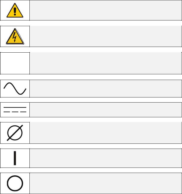
Throughout this manual the following symbols are defined:
WARNING, if instruction is not followed injury or serious equipment damage may occur!
CAUTION, internal parts have dangerous voltage present.
Risk of electric shock!
PE (Earth) – GND (Ground) PROTECTIVE GROUNDING TERMINAL:
A terminal which must be connected to earth ground prior to making any other connection to the equipment.
A terminal to which or from which an alternating (sine wave) current or voltage may be applied or supplied.
A terminal to which or from which a direct current or voltage may be applied or supplied.
This symbol indicated the word “phase”.
This symbol indicates the principal on/off switch in the on position.
This symbol indicates the principal on/off switch in the off position.
Modifications reserved |
Page 9/42 |
OPM_LPS_3UI_50K_60K_0US_V010.doc |
Installation Guide LP 33 Series 50-60 kVA |

2LAYOUT
2.1 LAYOUT LP 33 Series / 50 & 60 kVA
Fig. 2.1-1 General view stand-alone |
Fig. 2.1-2 General view stand-alone with open door |
Fig. 2.1-3 General view |
Fig. 2.1-4 General view with open door |
Modifications reserved |
Page 10/42 |
OPM_LPS_3UI_50K_60K_0US_V010.doc |
Installation Guide LP 33 Series 50-60 kVA |

Fig. 2.1-5 Control panel
1
2 CI Q1 Q2 FTM3 RC RPA SNMP
X1
X2
Opening for input and output of cables
Battery shelves
Customer Interface Board (optional)
UPS output switch
Manual bypass switch
Battery breaker
Relay card
RPA parallel board (optional)
Advanced SNMP Card (optional)
Terminals for common mains input connection (rectifier + bypass)
Terminals in case of dual mains input (optional)
|
X3 |
Terminals for load output connection |
|||
|
X4 |
Terminals |
for |
external |
battery |
Fig. 2.1-6 General view without protection panels |
connection |
|
|
|
|
|
|
|
|
||
Modifications reserved |
Page 11/42 |
OPM_LPS_3UI_50K_60K_0US_V010.doc |
Installation Guide LP 33 Series 50-60 kVA |
3INSTALLATION
3.1TRANSPORT
The UPS is fixed on transport socket suitable for forklift, which include a special layer of Ethafoam to protect the equipment against the transport shock.
Normally the UPS is packaged with carton box.
On request the equipment can be packaged in wooden case.
Move the UPS in its original package to the final destination room.
Do not stack other package on top: they could damage the upper side of the cabinet.
NOTE !
When moving the UPS, pay attention to:
|
|
|
|
|
|
|
|
|
|
|
|
|
|
|
|
|
|
|
|
|
|
|
|
|
|
|
|
|
|
|
|
|
SENSITIVE |
|
SENSITIVE |
|
SENSITIVE |
||||||||||||||
FRAGILE |
|
|
|||||||||||||||||||||||
TO DAMPNESS |
|
TO HEAT |
|
TO FROST |
|||||||||||||||||||||
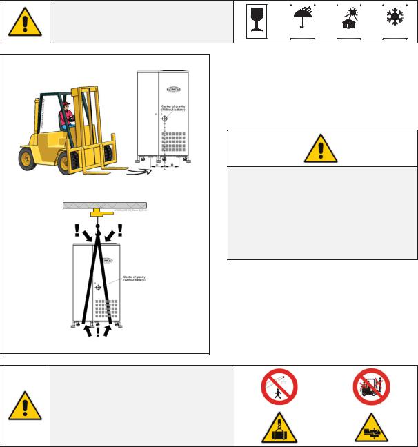
Forklift
Crane
Fig. 3.1-1 LP 33 Series lifting
Forklift
The UPS may be lifted with a forklift in upright position from right and left side.
Take note of the center of gravity marked on the package.
NOTE !
Check for sufficient floor and elevator loading capacity.
Transport UPS only in upright position.
Do not stack other package on top of the UPS.
Crane
If the UPS has to be lifted by crane, use suitable carrying belts taking note of the center of gravity marked on the package.
Take all necessary precautions to avoid damage to the cabinet while hoisting the UPS
WARNING !
When loading / downloading and when
moving the UPS, it is forbidden:
When loading / downloading and when moving the UPS, pay attention to:
Modifications reserved |
Page 12/42 |
OPM_LPS_3UI_50K_60K_0US_V010.doc |
Installation Guide LP 33 Series 50-60 kVA |
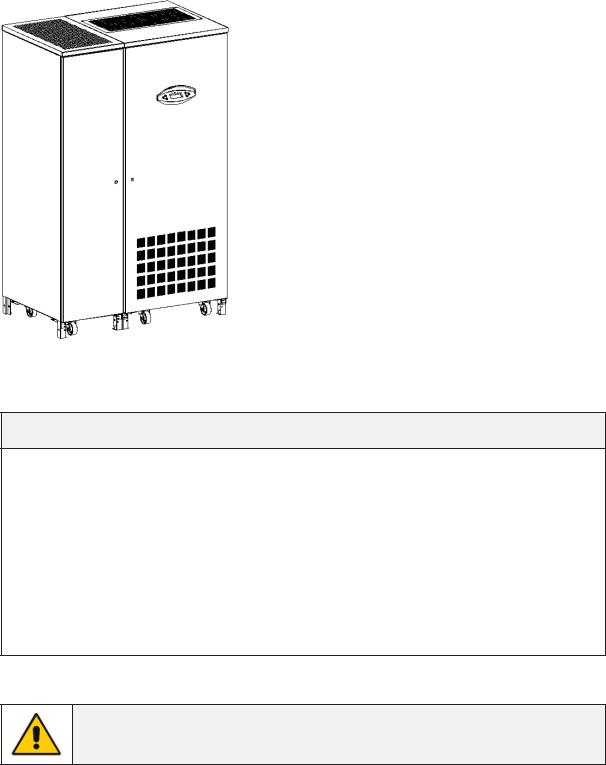
3.1.1Dimensions and weight
Fig. 3.1-1 LP 33 Series / 50 & 60 kVA
LP 33 Series / 50 & 60 kVA
Dimensions (W x D x H) |
45.28” x 29.61” x 71.85” |
||||
1150 x 752 x 1825 mm |
|||||
|
|||||
|
|
|
|
||
UPS weight without battery |
1015 lbs |
/ |
460 Kg |
||
|
|
|
|
||
UPS weight with battery 33 Ah (48 blocks) |
2139 lbs |
/ |
970 Kg |
||
|
|
|
|
||
UPS floor loading without battery |
109 lbs/sq.ft |
/ |
532 Kg/m2 |
||
|
|
|
|
||
UPS floor loading with battery 33 Ah (48 blocks) |
230 lbs/sq.ft |
/ |
1122 Kg/m2 |
||
|
|
|
|
||
UPS with standard shipping |
1081 lbs |
/ |
490 Kg |
||
NOTE !
The weight of each single piece is marked outside the package!
Modifications reserved |
Page 13/42 |
OPM_LPS_3UI_50K_60K_0US_V010.doc |
Installation Guide LP 33 Series 50-60 kVA |
 Loading...