


2508
Gerapid
Type 2508, 4008, 5008, 6008
UL LISTED - HIGH SPEED DC CIRCUIT
BREAKERS
WITH ARC CHUTE 1X2
USER MANUAL

2 Design and specifications are subject to change without notice S47183De rev.02 2011-03-14
INDEX
1. Warnings .............................................................................................. 3
2. General Usage Conditions. .......................................................... 3
2.2 Installation ........................................................................................ 4
2.2.1 Operational environment
2.2.2 Installation and interfaces ................................................ 4
2.3 Usage .................................................................................................. 4
2.3.1 Supply and load ..................................................................... 4
2.3.2 Adjusting the over current release ................................ 4
3. Technical Information .................................................................... 5
3.1 Introduction ...................................................................................... 5
3.1.1 Key features and construction overview. .................. 5
3.2 Components and accessories ................................................. 5
3.2.1 Contact system ...................................................................... 5
3.2.2 Arc chute ................................................................................... 5
3.2.3 Mechanism ............................................................................... 6
3.2.4 Overcurrent release OCT .................................................. 6
3.2.5 ED impulse coil release ...................................................... 7
3.2.6 Auxiliary tripping devices ................................................... 7
3.2.7 Forced tripping release ...................................................... 7
3.2.8 Manual operation lever ...................................................... 8
3.2.9 Auxiliary switch ....................................................................... 9
3.2.10 Indicators ................................................................................ 9
3.2.11 Closing solenoid drive ....................................................... 9
3.2.12 Operation counter .......................................................... 10
3.2.13 UL type of local and remote interlock ................... 10
3.2.14 Electronic control system ........................................... 10
3.3 Technical data table................................................................. 12
3.4 Control circuits data ................................................................. 13
4. Electrical Circuits ........................................................................... 14
4.1 Controls layout ........................................................................... 14
4.2 External connections to the breaker. ............................... 15
4.3 Standard wiring diagrams .................................................... 16
4.3.1 Wiring code positions ...................................................... 16
4.3.2 Breaker Internal Control Power Supply .................... 17
4.3.3 NEKO control circuit ......................................................... 18
4.3.4 SU control circuit ................................................................ 19
4.3.5 Shunt trip control circuit ................................................ 20
4.3.6 Zero Voltage release ......................................................... 23
4.3.7 Indicators ............................................................................... 24
4.3.8 Auxiliary switches ............................................................... 25
4.3.9 Operation counter and interlocks ............................... 26
5. Dimensions & Safety distances ............................................... 28
5.1 Safety distances. ......................................................................... 28
5.2 Outline drawings ......................................................................... 29
5.2.1 Outline of Gerapid 2508,4008-drawout version ... 29
5.2.2 Outline of Gerapid 2508,4008-fixed version ......... 30
5.2.3 Outline of Gerapid 5008,6008-drawout version ... 31
5.2.4 Outline of Gerapid 5008,6008-fixed version ......... 32
5.2.5 Gerapid 2508, 4008 with H / H terminals – fixed
version ................................................................................................. 33
5.2.6 Gerapid 2508, 4008 with V / V terminals – fixed
version ................................................................................................. 35
5.2.7 Gerapid 2508,4008-drawout fingers ........................ 37
5.2.8 Gerapid 5008, 6008 V/V terminal–fixed version 39
5.2.9 Gerapid 5008, 6008 – drawout fingers .................... 41
6.1 List of inspections ...................................................................... 43
6.1.1 General visual inspection ................................................ 44
6.1.2 General functional inspection ....................................... 44
6.1.3 Inspection of the arc chute ............................................ 44
6.1.4 Inspection of the contact system ............................... 45
6.1.5 Inspection of contacts’ tilt and gap .......................... 46
6.1.6 Inspection of the screw connections ....................... 46
6.1.7 Inspection of the mechanical components ........... 46
6.2 List of maintenance tasks ...................................................... 47
6.2.1 Contact system . ................................................................. 48
6.2.2 Layout of control PCB inside control box ............... 51
6.2.4 Replacement of the control boards .......................... 51
6.2.5 Adjusting the auxiliary switch ...................................... 53
6.3 Spare parts lists. ......................................................................... 54
6.3.1 Mechanical spare parts. ................................................. 54
6.3.2 Electrical spare parts ....................................................... 55
6.3.3 Recommend materials for selected works ............ 55
7. Customer Support ......................................................................... 56
7.1 Options overview. ...................................................................... 56
7.3 Glossary .......................................................................................... 57
7.4 Troubleshooting .......................................................................... 58
7.5 GE service teams ........................................................................ 59
2011-03-14 S47183De rev.01 Design and specifications are subject to change without notice 3
1. Warnings
Warnings:
During operation, electrical equipment carries
dangerous voltages. In addition, circuit breaker
emits hot, ionized gases when switching
currents, especially short circuit currents.
Installing, commissioning, maintaining, changing
or refitting of this equipment must be carried out
only by qualified and suitably trained personnel
and under strict observation of national and
international applicable safety regulations.
During their operation, circuit breakers must be
equipped with appropriately fitted covers, e.g. in
suitable enclosures or panel boards. Safety
distances must be preserved. Suitably trained
service personnel shall only carry out certain
works.
Non-compliance with these warnings may result
in death, and/or severe physical damage and
extensive damage to equipment.
Prior to carrying out maintenance, inspection or
checks, the circuit breaker must be open, the
both terminals must be grounded, the circuit
breaker must be switched off and the control
plugs removed.
Manual activation of the breaker while energized
is forbidden. Manual activation must only be
used for maintenance and inspection purposes,
when breaker power is off and grounded.
The circuit breaker consists of high energy
moving components. Do not touch the circuit
breaker while it is being switched ON (closing) or
OFF (opening). There is a high risk of major injury.
The control circuits may include capacitor banks,
which can be charged with dangerous voltages.
Work on this section must be carried out
carefully.
2. General usage conditions
2.1 Transportation and storing
The breaker is transported on wooden palette. It is fixed by
shrunken plastic film. A cardboard box covers the breaker on
the palette. Truck, railway, airplane and ship transport is
possible. In case of sea transport, special protection against
salty and humid environment is provided.
The circuit breaker must always be transported to the
installation site vertically and fully packed. The packaging
protects the device against damage and dust; it should only
be removed prior to installation.
If the packaging is damaged, the breaker and the arc chute
must be inspected for damage. Ensure that all packaging
materials have been carefully removed prior to breaker
installation.
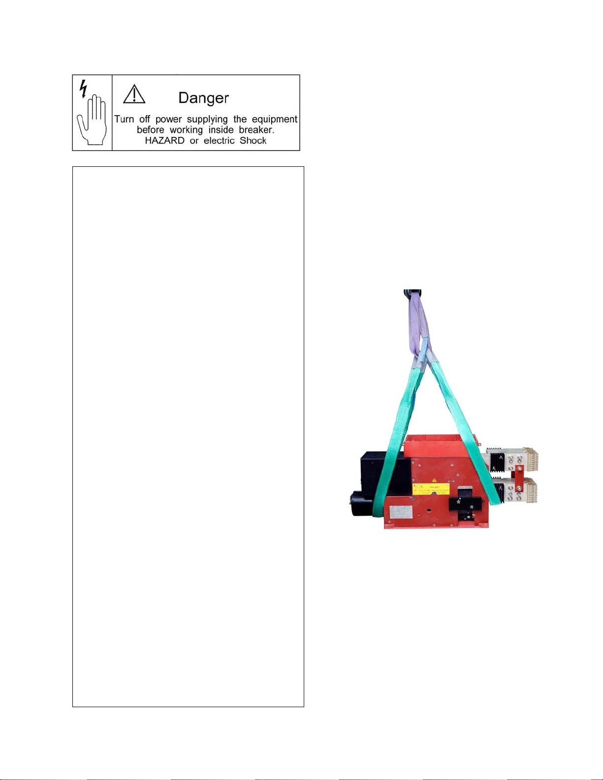
For handling the unpacked breaker use canvas slings and
position them below the closing drive (a) and below the lower
terminal (b) [Fig. 1]. Always follow information labels, which
are placed on the breaker’s frame.
Fig. 1 Handling the breaker
WARNING: Breaker and arc chute must be transported
separately. Never handle the breaker with arc chute installed!
Take care that the bottom isolation plate of the unpacked
breaker is not damaged during handling. Do not push the
breaker back and forth on any rough surface.
The breaker’s weight, including arc chute is listed in Table 1,
page 12. Arc chute’s weight is ca. 30 kG (66 lb)
WARNING:
Store in original packaging!
Do not store outdoors!
Use protection against crush and blow!
Do not store the breaker in a damp area!
Storing temperature-range–25 °C(-13F)…+55 °C(131F)!
a
b
4 Design and specifications are subject to change without notice S47183De rev.02 2011-03-14
2.2 Installation
2.2.1 Operational environment
The breaker, as delivered, is NEMA 1 protected. It is intended
for service in indoor applications, without pollution, with non-
conductive dust, protected against high humidity and heavy
condensation. Low conductivity dust deposit due to frequent
condensation of humidity is acceptable. For general
environmental conditions refer to EN 50123-1 - annex B, and
IEC 60947, class PD3.
The breaker can operate at rated current within ambient
temperature range of –5 °C to +40 °C (23 °F to 104 °F).
Maximum operating ambient temperature is +55 °C (131 °F)
with continuous current derated by 10 %.
The breaker can operate at altitudes up to 2000 m (~6500 ft)
without derating.
The breaker shall not be subjected to strong vibrations.
Maximum vibrations of 0.5 g per 30 sec in vertical and
horizontal directions are allowed.
Air shall be clean and its relative humidity shall be not more
than 50 % r.h. at the maximum temperature of +40 °C
(104 °F). Relative humidity may be higher if the temperatures
are lower, for example, 90 %r.h. at +20 °C (68 °F). Slight
condensation might occur during variations of temperature.
2.2.2 Installation and interfaces
The lower and upper main terminals must be connected
directly to the main cables or bus bars.
WARNING: The breaker must only be used in an upright
operation position with the arc chute in place and fully
secured.
After arc chute installation check for tightness both
connections to the arc runners. See Fig. 48-2
The safety distances as listed in section 5.1 shall be
maintained to grounded or insulated parts. Suitable measures
must be taken to protect personnel from arcs.
Strong, external magnetic fields, caused by improperly
located supply conductors or stray fields from other devices,
can lead to a shift of the trip setting thresholds. This may
result in premature tripping, or no tripping at all during low-
level short circuit current events. This has to be accounted for
when installing and operating the device with shielding added
if appropriate.
The control wires must be connected to the control terminals
as shown in the schematic circuit diagrams. The protective
grounding wire must be connected at the marked contact
[Fig. 2].
Fig. 2 Termination for grounding wire
2.3 Usage
2.3.1 Supply and load
In accordance with its type, the breaker has been designed
for the current and voltage listed in Table 1, section 3.3.
During continuous operation, breaker must only be loaded up
to its maximum rated current. Load currents in excess of
breaker nameplate rating are allowable for brief periods only.
Refer to the short time currents listed in Table 1.
Do not exceed the rated nominal voltage shown on the
breaker’s nameplate.
Supply voltage for the drive and the auxiliary-tripping devices
shall be within the specified control voltage range. Maximum
current values for the auxiliary-tripping devices are listed in
Table 2a.
WARNING: Plugging in or unplugging of the auxiliary
connectors (-X2 :1/:2) (-X3 :4/:5) is only allowed with
disconnected primary (mains) and secondary voltages.
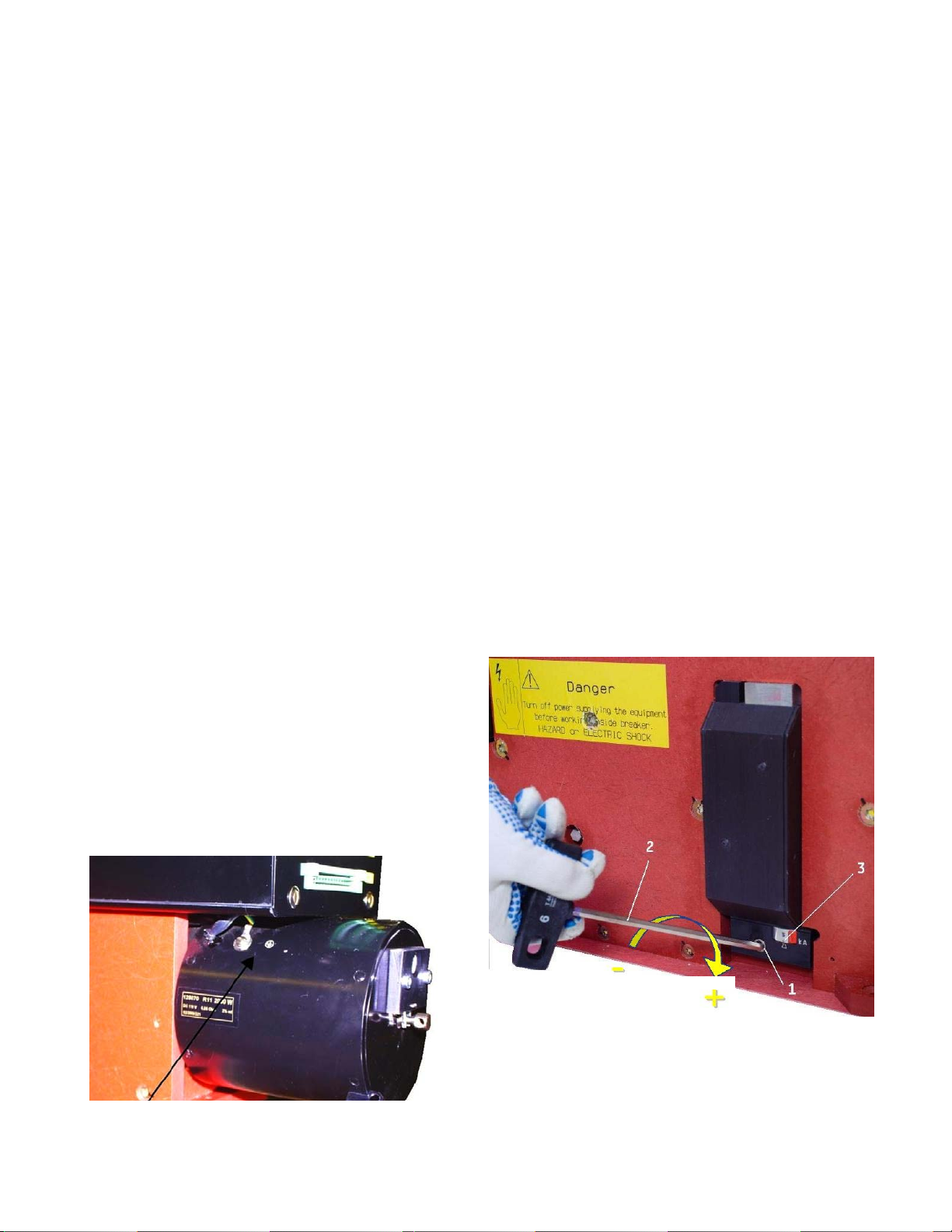
2.3.2 Adjusting the over current release
OCT is an over-current tripping release , which trips and
releases the breaker in case of overload or short circuit
currents. This is an instantaneous and direct acting device.
If equipped with an adjustable OCT, the response threshold
can be easily adjusted [Fig.3], by turning the adjustment nut
(1) with a SW6 hexagon wrench (2).
The adjustment must only be carried out after the breaker
has been disconnected from the main circuit. For fixed
installations breaker’s main terminals shall be grounded.
Turning the adjustment screw clockwise increases the trip
threshold, turning the screw counter-clockwise decreases the
tripping threshold. Align the arrow and the desired marking 3,
to perform adjustment.
Fig. 3 Setting of the OCT unit
2011-03-14 S47183De rev.01 Design and specifications are subject to change without notice 5
3. Technical information
3.1 Introduction
UL listed type of Gerapid is a DC single pole, high-speed, air
circuit breaker available in either fixed-mounted or drawout
versions. This breaker has been primarily designed for use in
traction applications. The new UL version can be can be used
as a feeder breaker in various other installations, such as
industrial plants (metals industry), as field breakers for motor
and generator field applications, and as disconnects for DC
drives to name a few. Current ratings from 2500 A up to
6000A and voltage ratings up to 800V are available with UL
certification. For different current and voltage ratings please
refer to non UL version of the breaker.
3.1.1 Key features and construction overview.
UL listed and type tested up to 200 kA acc. ANSI C37.14.
Fixed and draw-out versions with available OEM cell.
High speed TRIP with opening delay less 3ms.
High speed internal, self-powered, direct acting,
instantaneous and adjustable bidirectional OC release .
High speed electrodynamic impulse release with or without
capacitor and charging unit.
High speed CLOSE (approx. 150 ms), by means of solenoid
drive with integral control circuit.
Mechanical forced tripping device for safe withdrawing.
Shunt trip or zero-voltage release for service opening.
Up to 8 form C auxiliary contacts.
Variable main terminal configurations.
Plug connectors for auxiliary circuits.
Hand lever for manual actuation.
Contact Position indication.
Internal power supply with a wide range of input supply
voltage options.
2-stage main contact system.
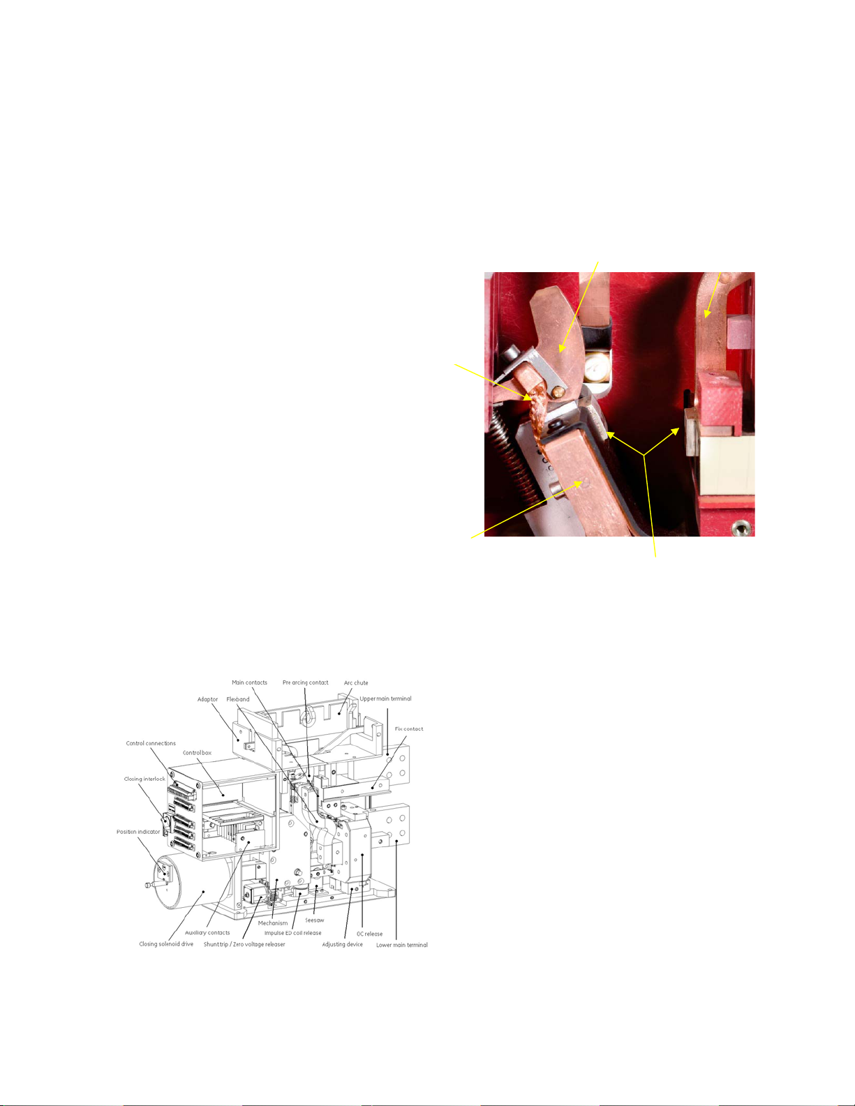
Compact, enclosed and modular design [Fig. 4] with high
serviceability and extensive accessories.
Easily accessible control and auxiliary connections
Fig. 4 Modular construction overview
3.2 Components and accessories
3.2.1 Contact system
All Gerapid breakers are equipped with a two-stage contact
system [Fig. 5], consisting of a main contact and an arcing
contact. With this proven design, the main contact is not
subjected to any appreciable wear or tear.
The main contact is made of a silver composite material. The
arcing contact and link braid are made of copper and can be
easily replaced.
The flexible bend is linked to the arcing contact by means of
very tight braid.
Fig. 5 Two -stage contact system
3.2.2 Arc chute
Compact and modular design of the arc containment system
requires no additional magnetic support and allows small
safety clearances with high breaking capacity up to 200 kA.
Because of the compact dimensions, these breakers can be
installed in extremely small enclosures (from 500 mm; 1.65 ft)
and offers a cost-effective solution for replacements.
An arc chute adaptor [Fig.43] is used to mount the various arc
chutes for different operating voltages on the breakers. The
arc chutes consist of a highly durable, arc-proof material, in
which the arc plates have been integrated. The arc plates
split the arc into partial arcs and increase the arcing voltage
by multiplying the anode and cathode voltage drop. Because
of their high heat capacity, the plates and arc chute walls
absorb a large amount of the arc’s energy.
Arcing Contact
Flex
Braid
Flex Band
Arc
Runner
Main Contacts
6 Design and specifications are subject to change without notice S47183De rev.02 2011-03-14
3.2.3 Mechanism
The Gerapid is equipped with a modular designed
mechanism, which is wear-resistant and nearly maintenance-
free. This mechanism ensures an extended electrical and
mechanical endurance of the breaker as well as a high level
of safety under all operation conditions.
Breaker can operate 20 000 cycles without maintenance
when opened by the shunt trip or zero voltage release coils,
and 1 000 operations by means of impulse coil or OCT
releases.
This mechanism is mechanically latched in the CLOSED
position. A mechanically latched mechanism offers
advantage compared to often used electro magnet holding
system. No auxiliary control power source is required to keep
breaker closed.
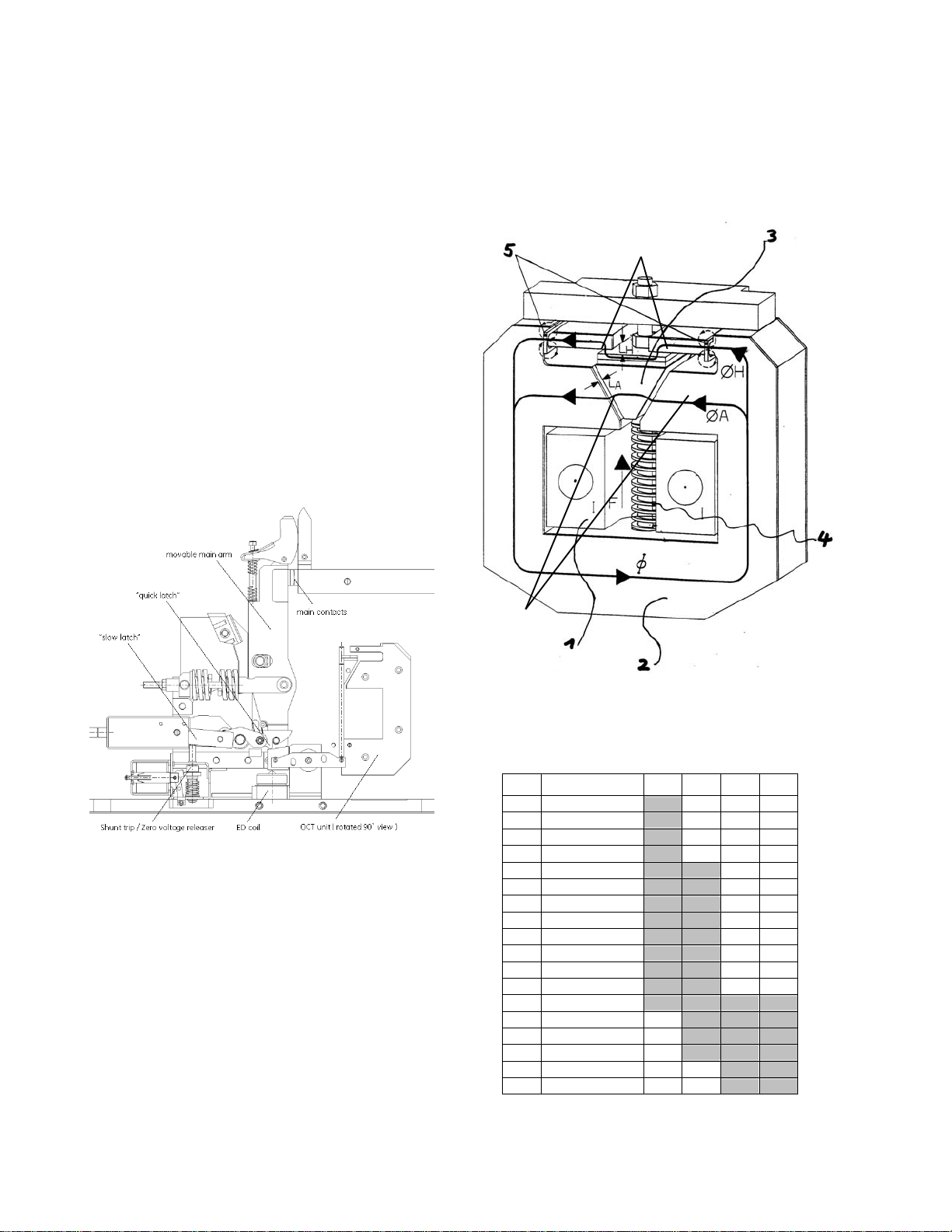
The mechanism is provided with two tripping latches [Fig. 6].
One latch, called “slow latch”, is used for opening under
normal conditions, like actuation of shunt trip or zero-voltage
release. The second one, “quick latch”, de-clutches the main
contact arm from the mechanism and opens the contacts
with an extremely short delay. This is used when interrupting
short-circuit or overloads. All safety releases operate onto
“quick latch”.
Different main springs are used in mechanisms for different
breaker frames. Therefore mechanisms cannot be exchanged
between breakers of different frame.
Fig. 6 Latching and tripping system
3.2.4 Overcurrent release OCT
The OCT release is a magnet with two magnetic circuits,
optimizing the twin magnetic field principle [Fig. 7]. This
technology ensures equally fast tripping in both current
directions. This system does not require an auxiliary control
voltage to operate. It is a direct acting and instantaneous
tripping device.
The OCT consists of the holding circuit [6], the movable
armature [3] and the tripping circuit [7]. The holding and the
tripping magnetic circuits are both excited by load current [1].
Until the static overload release’s response threshold has
been reached, the armature [3] is held in position by the
holding flux (H) [2] and the counter spring’s force [4]. Once
the load current exceeds the set static response threshold,
the attraction flux (A) [2] takes over and rapidly pulls down
the flexible armature [3]. During this operation, the armature
hits the seesaw, which releases the quick latch in the
mechanism. The latch and contacts are opened immediately.
The OCT is available in either a fixed setting or adjustable over
specific ranges. On the adjustable OCT, the response
threshold can be easily adjusted by turning the adjustment
nut with a SW6 hexagon wrench. The available ranges are
described in the table below. Other ranges might be possible
on request.
Fig. 7 OCT device.
Default tripping bands for the OCT release
1)
.
1) Customer specific bands on request.
Code
OCT bands 2508 4008 5008 6008
A 1.5 kA – 2.5 kA
B 1.5 kA – 3 kA
C 1.5 kA – 4 kA
D 1.5 kA – 5 kA
E 2 kA – 6 kA
F 2 kA – 7 kA
G 2 kA – 8 kA
H 2,5 kA - 5,5 kA
J 3 kA – 7 kA
K 3 kA – 8 kA
L 3 kA – 9 kA
M 3 kA – 12 kA
N 5 kA – 10 kA
P 6 kA – 14 kA
Q 7 kA – 15 kA
S 8 kA – 18 kA
T 10 kA – 16 kA
U 12 kA – 24 kA
6
7
2011-03-14 S47183De rev.01 Design and specifications are subject to change without notice 7
3.2.5 ED impulse coil release
ED (electrodynamic) impulse release is a high speed trip coil,
and is intended to be used with external protective relays or
systems monitoring current increase. External relays must be
provided and installed by the customer. The ED coil must be
energized by a capacitor storage trip device. An optional
internal capacitor trip and control (NEKO), can be furnished
with the breaker or must be supplied by the user externally.
Rated voltage of 300 V and capacity of 2 000 µF is required. If
a fault is detected by the external relay, a firing signal must be
sent to the capacitors’ control unit (internal NEKO) causing
NEKO unit to discharge its energy into ED coil. If the capacitor
and controls are external, then user must supply the 300V
directly to the ED coil. The coil releases the quick latch and
opens breaker’s contacts in 3-4 ms. ED trip coil is an optional
accessory. It can be selected as a complete set consisting of
ED coil and electronic control unit with C-bank called NEKO, or
just the ED coil with user supplied capacitor trip unit .
The external release signal shall be 6 V to 24 V DC, and shall
be connected at terminals (-X2 :10 / :11) in standard wiring
scheme.
WARNING: Firing signal voltage of 6 VDC to 24 VDC must be
filtered. There should be no spikes on the signal of duration
less 3 ms. This can lead to defect of the NEKO board. Maximum
duration of the firing signal must not exceed ~1 sec. Longer
duration can cause the NEKO board to overheat! It is
recommended to use an auxiliary breaker contact in series
connection with firing circuit (-X2 :10/:11). It will automatically
cut off the firing circuit after breaker opening.
Fig. 8 ED impulse coil with seesaw interface
3.2.6 Auxiliary tripping devices
The breaker can be equipped with either a shunt trip (ST) or a
zero voltage release (UVR). It is not possible to have both
devices installed in the same breaker. Both devices are
interchangeable.
In normal configuration, the internal voltage converter
transforms the external voltage into 24 V DC, which is
required by standard ST or UVR. Both devices are tripped by a
dry contact connected as shown in section 4.3, [Fig. 27a] and
[Fig. 28]. Optionally, the ST can be ordered for connection
directly to an external 24 V DC (± 5%), 125 V DC or 220 V DC
supply. A double winding shunt trip coil is available with this
option for 125/220 V DC external control supply, for back-up
or redundancy.
The ST is used for remote actuation and normal opening
operations.. It is designed for short time operation with max.
duty cycle of 9 %. ST’s supply is connected through auxiliary
breaker contacts, which cut off supply voltage after opening.
This protects ST against overheating.
WARNING: Manual closing of the breaker with ST installed,
while pushbutton OPEN is pressed and control power applied,
might lead to ST coil’s overheating and damage.
The UVR [Fig. 9] can be used for remote actuation and, in
combination with an internal electronic control, for voltage
control. The UVR releases at voltage interruption or supply
voltage drop below 20 V. In these cases UVR trips the breaker.
It is therefore possible to use this device in combination with
the electronic trip unit for voltage monitoring, where an
unintended re-start of machines after a temporary voltage
breakdown is to be prevented.
The UVR is intended for continuous operation. Its rated power
is 10 W. Due to its operational mode, the UVR is a self-
monitoring device, i.e. when the breaker is tripped upon a
break of the pilot wire (EMERGENCY-OFF principle).
Fig. 9 Zero voltage release in the mechanism’s module.
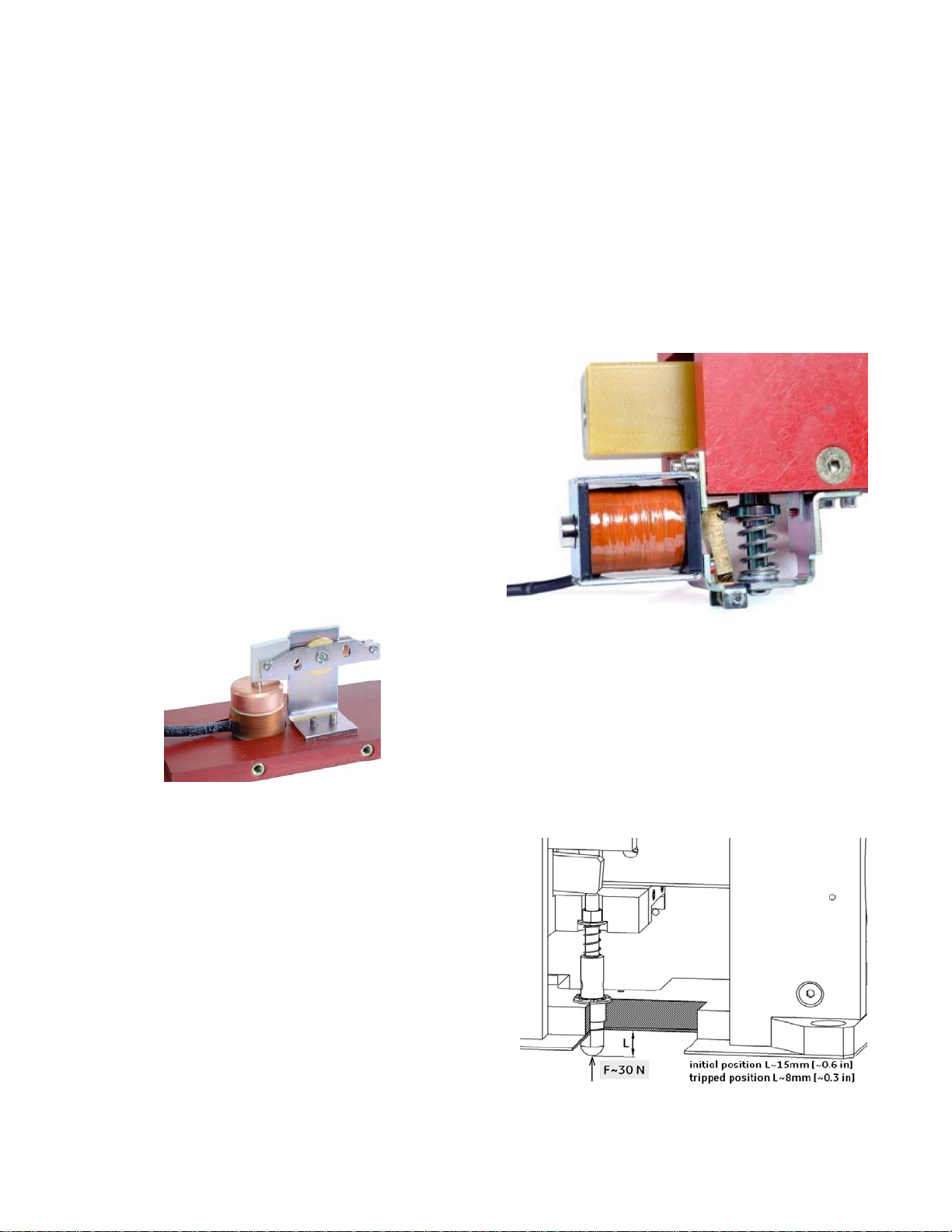
3.2.7 Forced tripping release
For drawout installations or as an manual trip interlock, the
forced tripping release (FT) is installed in the breaker [Fig. 10a]..
This unit, which mounts in the breaker base plate,
mechanically trips the breaker, by pressing the pin against the
seesaw linkage. Force required to trip the breaker is about
30 N (~7 ft-lb). The tripping pin position is as on Fig. 10b.
Fig. 10a Forced tripping release
8 Design and specifications are subject to change without notice S47183De rev.02 2011-03-14
With a correctly designed interlock in an enclosure, FT provides
safety-tripping function. During withdrawal operation of the
trolley, the breaker is tripped BEFORE its main terminals
disconnect from the mains.
Fig. 10b Positioning of the forced tripping pin
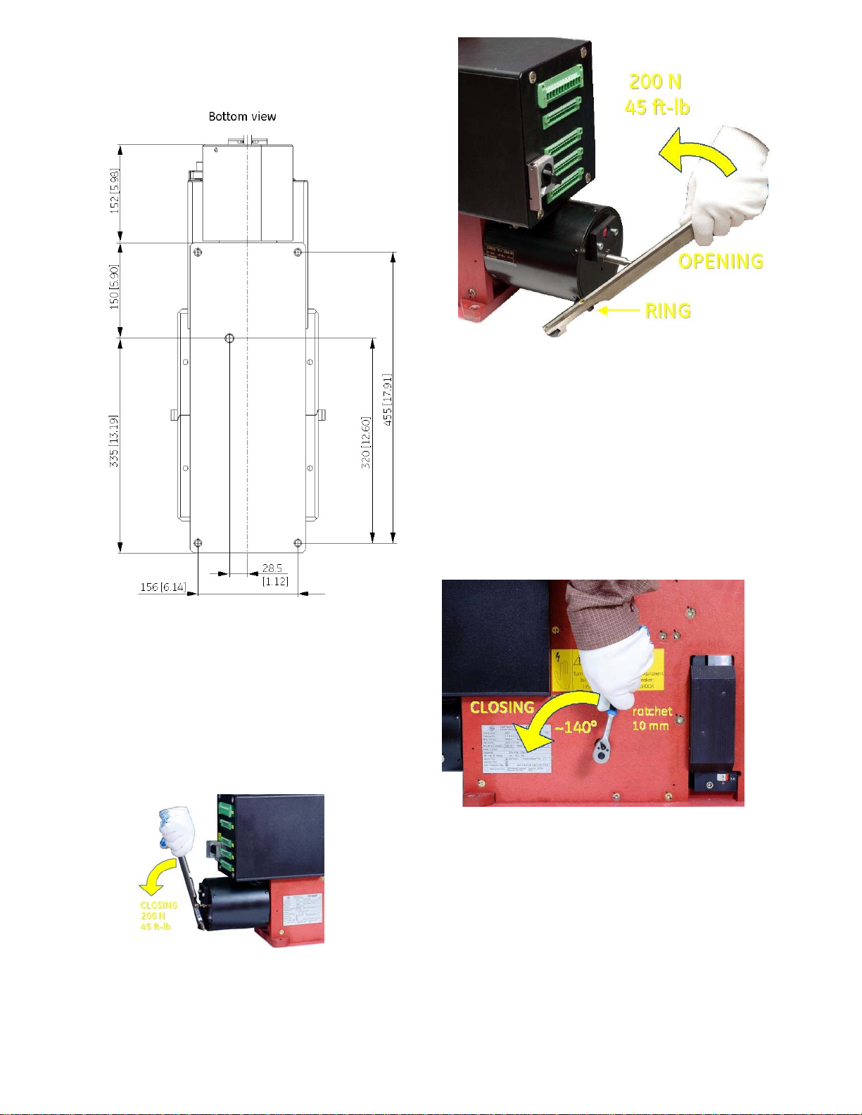
3.2.8 Manual operation lever
Optionally, a hand lever for manual closing and opening
operation during maintenance is available. This tool must not
be use while breaker is energized!
To close the contacts, install hand lever on the drive’s rod, and
pull it out smoothly until latches snap [Fig. 11a].
To open the contacts, install the tool into the ring and push it
hard against the drive’s rod until breaker opens [Fig. 11b].
WARNING: Manual closing and opening – only during
maintenance!
Fig. 11a Closing operation by using hand lever
WARNING: Manual closing and opening – only during
maintenance!
Fig. 11b Opening operation by using hand lever
Alternative manual closing and opening operation is possible
by rotating the main shaft of the breaker mechanism, which
is accessible from the side. Use 10 mm hexagon-socket
wrench to OPEN/CLOSE [Fig. 11c].
WARNING: Pay attention to control rotation speed of the shaft
during manual opening. Impede the wrench to avoid hitting it
to the ground, which may lead to a hand injury.
WARNING: Manual closing and opening – only during
maintenance!
Fig. 11c ON/OFF operation by using a 10 mm wrench
2011-03-14 S47183De rev.01 Design and specifications are subject to change without notice 9
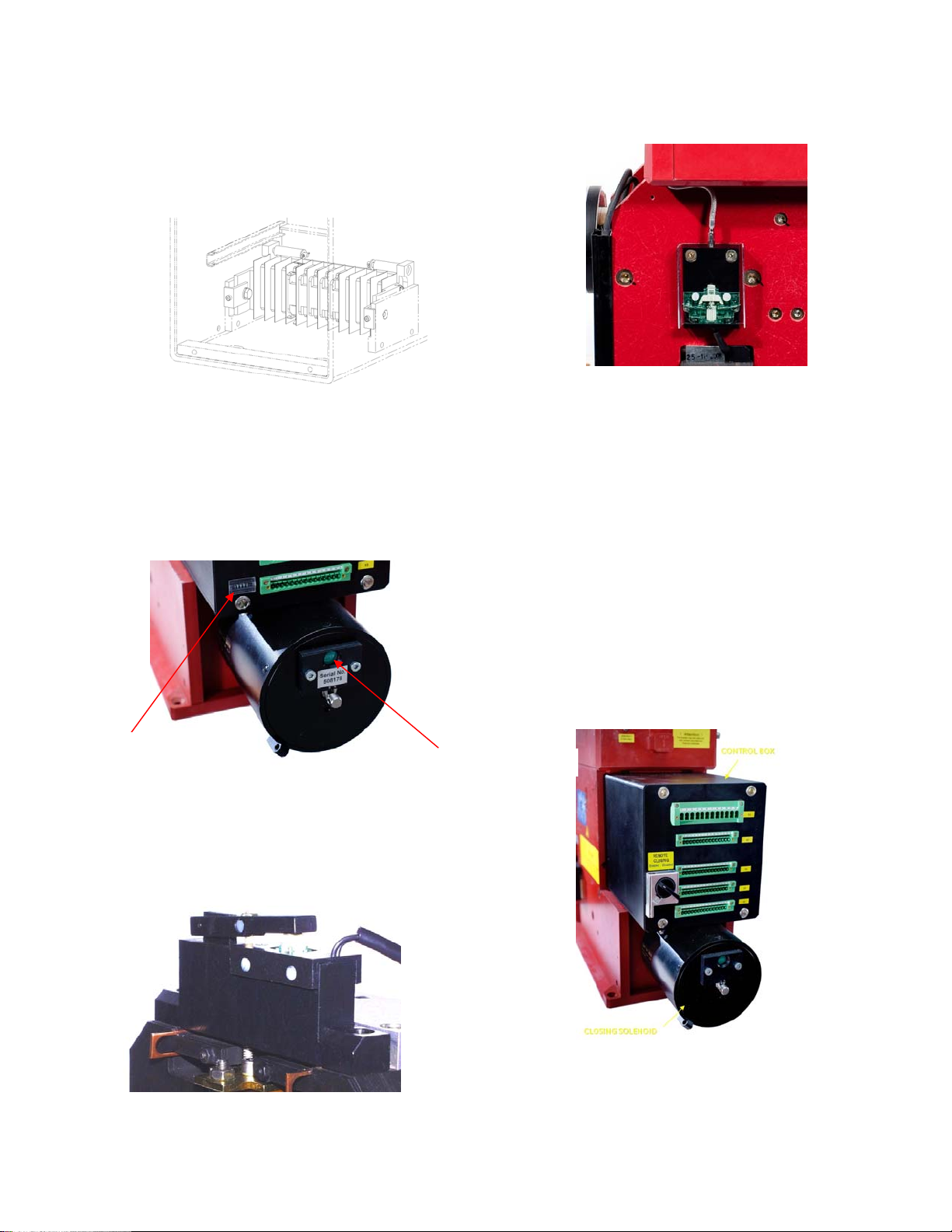
3.2.9 Auxiliary switch
UL listed breaker is equipped with 3, 5 or 8 isolated, form C,
invertible auxiliary contacts (1 NO/NC each). The movable main
arm activates the contacts. The contacts are wired to 15-pin
control terminals (-X4 and -X5), on the front of the control box
[Fig. 30]. Conventional thermal current rating is10 A. Maximum
electrical ratings for switches are 1 A/230 V, 0.5 A/110 V and
0.3 A/220 V.
Fig. 12 Auxiliary contacts layout in control box
3.2.10 Indicators
POSITION INDICATOR is- mounted at the front of the closing
solenoid. It is mechanically switched by the solenoid’s shaft
and indicates position of the main contacts.
Green “OPEN” – means contacts are open
Red “CLOSED” – means contacts are closed
Fig. 13 Position indicator
Optionally, the circuit breaker can be equipped with following
indicators:
OC TRIP TARGET is a potential free, NO contact mounted at
the top of the OCT [Fig. 14]. Provides a signal when OCT
operates.
Fig. 14 OC trip target
ARC CHUTE INDICATOR – a potential free, NO contact mounted
on the sidewall. Locks electrically the closing drive when arc
chute is not installed on [Fig. 15].
Fig. 15 Arc chute indicator
3.2.11 Closing solenoid drive
A high power solenoid is used to perform fast closing
operation. This drive is mounted at the front of the breaker
and is enclosed in a grounded casing [Fig. 16].
Closing solenoid is supplied from an external power source,
independent from the breaker internal controls. Voltage level
must be defined at order placement. Rated power, depends
on breaker type, but is between 1.8 kW and 2.6 kW.
CLOSING is enabled by external dry contact closure (-X2 :4/:5).
Minimal close signal duration shall be 100 ms.
The closing drive system always includes a self-interrupt
control circuit (SU circuit board). This circuit enables short
activation with a time of ~150 ms. The SU switches power to
the solenoid and automatically disconnects it after ~400 ms.
The SU unit also prevents repeated drive closing, due to an
existing and continuous short circuit conditions and provides
an “anti-pumping” safety feature.
Fig. 16 Solenoid closing drive and control box
After a closing attempt, the switch-in mechanism is
electrically blocked for approximately 8 sec. Lock time
increases to 14 sec, if internal C-bank (NEKO) is present. This
prevents premature closing following a short circuit.
Operations Counter
Position Indicator
10 Design and specifications are subject to change without notice S47183De rev.02 2011-03-14
3.2.12 Operation counter
An operations counter is available on the UL Gerapid Breaker.
It is an electro-mechanical, non-resettable design, and
increments with each open/close cycle as long as control
power is available (manual operation of the breaker with
control power removed with not increment the counter).
.
Fig, 17.1 Control box with counter.
Fig. 17.2 UL with Close-Stop Interlock and Cover
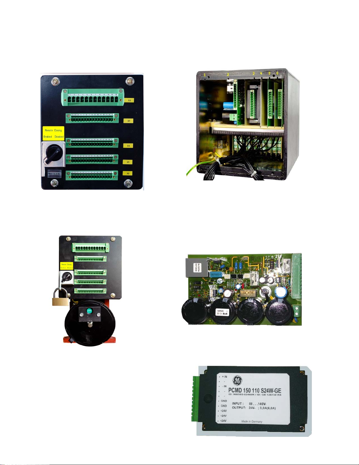
3.2.13 Remote/Local Close-Stop Interlock
As a standard feature on UL Labeled breakers, the Close-Stop
Interlock switch mounted on the control box front cover
provides the means to electrically block both local and remote
closing signals from closing the breaker. The selector switch
can be padlocked in the “Disabled” position for LOTO
procedures. The Close-Stop Interlock feature is optional on
non-UL breakers.
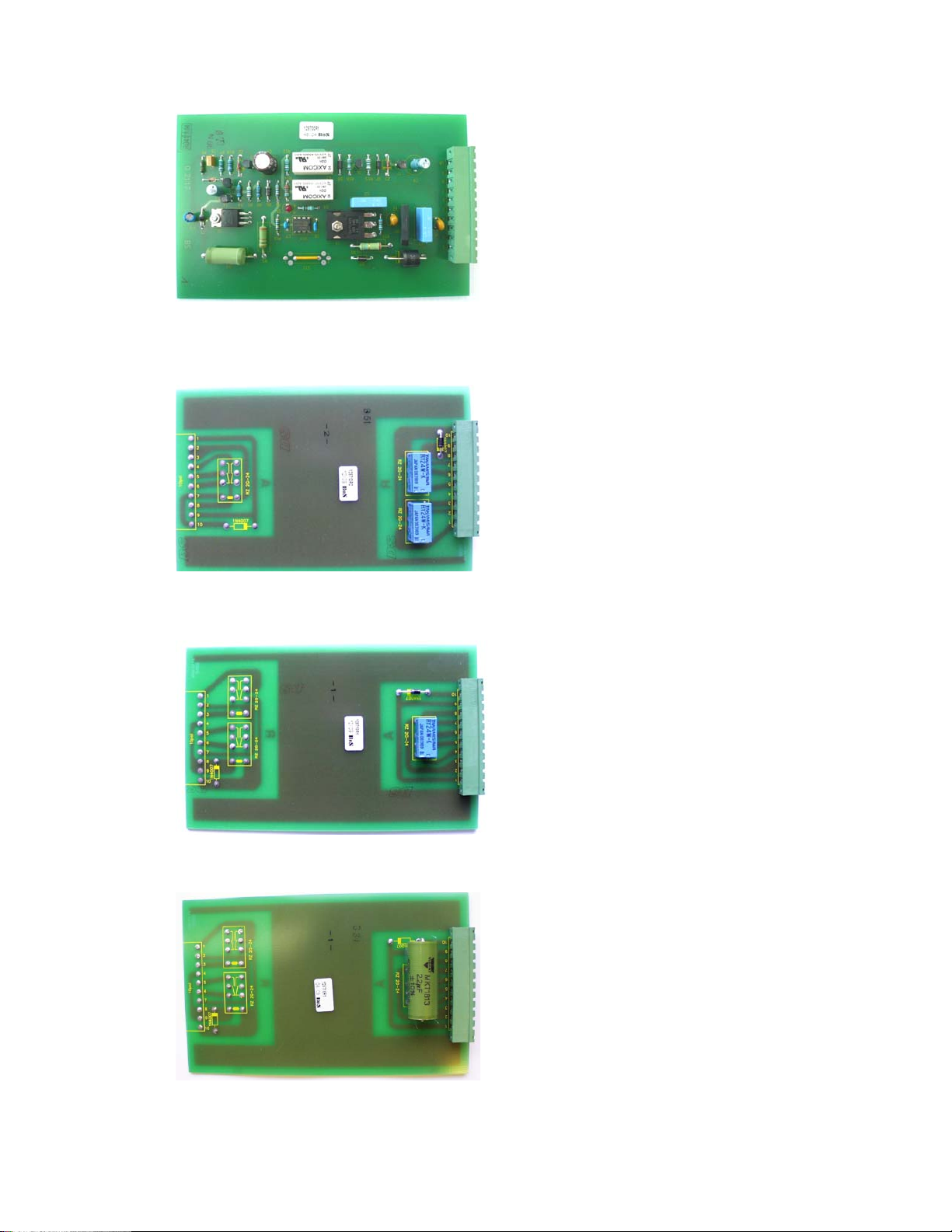
3.2.14 Electronic control system
All the control cards are installed in the upper compartment of
the control box [Fig. 18]. There are six slots. Slots 1 and 5 are
empty. Starting from left following cards are installed:
Fig. 18 Control box inside
Slot (2) NEKO control unit [Fig. 19-1] – internal control unit
with capacitor bank. Releases firing signal for ED coil (-X2
:10/:11) and provides indication of the capacitors charging (-
X3 :6/:7). NEKO control unit also blocks the firing signal until C-
bank is fully charged (~15 sec).
WARNING: NEKO unit requires a high quality firing signal. Be
sure, that voltage level is between 6 V…24 V DC and there are
no short spikes on signal (<3 ms). This might lead to major
defect of the NEKO control unit!
Fig. 19-1 NEKO control unit
Slot (3) Internal voltage converter [Fig. 19-2] - converts
external supply voltage (-X3:4/:5) to the internal 24 V DC.
Required by controls (except for the drive supply).
Fig. 19-2 Voltage converter 110V/24 V DC.
2011-03-14 S47183De rev.01 Design and specifications are subject to change without notice 11
3.2.14 Electronic control system
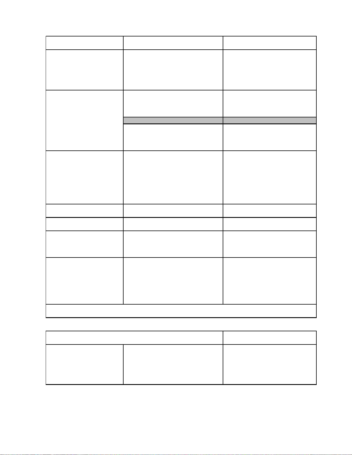
Slot (4) SU control unit – see point 3.2.11
Fig. 19-3 SU control unit.
(6) ST/UVR control unit – simple relay system. It controls
operation of shunt trip or zero voltage release.
Fig. 19-4a UVR control unit
Fig. 19-4b- ST control unit
Fig. 19-4c ST control card for external supply.
12 Design and specifications are subject to change without notice S47183De rev.02 2011-03-14
2011-03-14 S47183De rev.01 Design and specifications are subject to change without notice 13
3.4 Control circuits data
Control box terminals
1x12-pole AC 400 V, 20 A
4x15-pole AC 250 V, 8 A
Closing solenoid drive
1)
Rated voltage AC 120 V, 230 V and DC 125 V, 250 V
Operating range 80 % - 115 % of rated voltage
Power consumption Gerapid 2508 / 4008 1750 W / 2000 W
Power consumption Gerapid 5008 / 6008 2600 W / 2600 W
Minimal CLOSING command duration 100 ms
min.interval between two "CLOSE" operations ~8 s w/o NEKO installed; ~14 s with NEKO
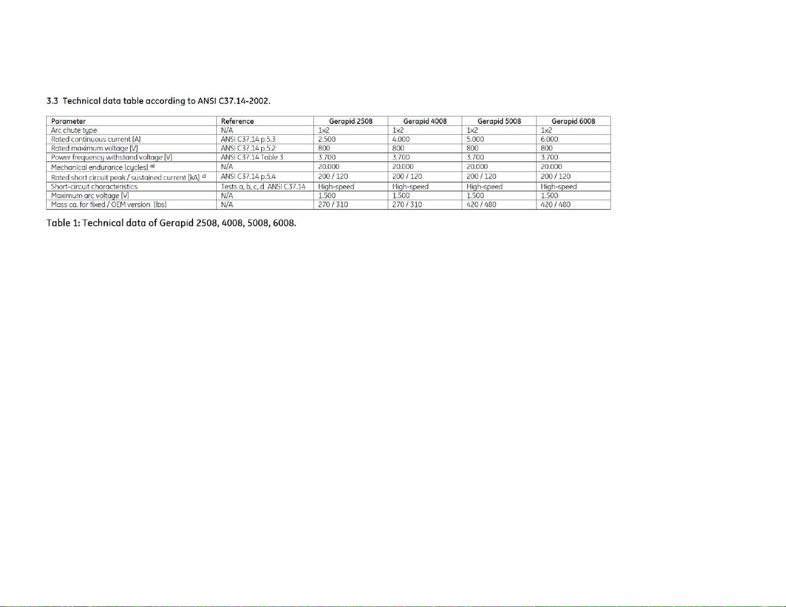
Internal voltage converter
1)
Input: Voltage range DC 88 - 145 V
for Gerapid 2607, 4207, 6007, 8007
Output: Voltage range DC 24 V (±5%)
Current 6 A permanent
Model description PCMD 150 110 S24W-GE
Input: Voltage range AC 115 - 240 V, DC 125 - 353 V
Output: Voltage range DC 24 V (±5%)
Current 3 A permanent, 5 A/100 ms
Model description PCMA 70 S24W-GE
Aux. contact HS 1…HS 8,
Rated operational voltage Ue/AC 230 V
OC trip target
Rated operational current Ie/AC-15 1 A
Arc chutes indicator
Conventional thermal current Ie/AC-12 (Ith) 10 A
Rated operational voltage Ue/DC 110 V / 220 V
Rated operational current Ie/DC-13 0.5 A / 0.3 A
Minimum current/voltage ratings 0,1 mA / 6 V DC
Contact duty (min. value) DC 10 V / 2 mA
Shunt trip standard
Rated voltage/power Uc/Pc 24 V / 100 W
Operating range: OFF 21.6 V - 26.4 V
Shunt trip double winded
Rated voltage/power Uc DC 125 V/ DC 220 V
Rated power for a single winding Pc 230 W
UVR
Rated voltage Uc 24 V
(Zero voltage release) Operating range: OFF < 4 V
Operating range: ON 24 V (±10%)
Power consumption ~ 10 W
ED impulse release
Required C-bank capacity 2000 µF
Charging voltage 300 V
Switching interval max. 2/min with 10 consecutive operations
Endurance 1 000 operations with 1 operation per 180 s
Firing signal level / duration
6 - 24 V / 100 - 1000 ms
Charging signalization relay AC duty AC 250 V/ 0.5 A - AC 120 V /1 A
DC duty : DC 220V/0.1A - DC 125V/0.3A - DC 10V/3A
1)
Standard ambient conditions acc. to EN 50123-1 Attachement B. For meeting outside of this standard range, please call back.
Table 2a: Technical data of auxiliary circuits
Components Technical datas of control circuits
Us / In
SU-Control CLOSE-push-button -S1 DC 24 V / approx. 10 mA
ST releasing push-button-S2 DC 24 V / approx. 4 A short time
UVR releasing push-button -S2 ( -X2 :6 / :7) DC 24 V / approx. 10 mA
push-button -S2 ( -X2 :8 / :9 ) DC 24 V / approx. 450 mA
ED-coil tripping w/o NEKO push-button -S3 DC 300 V / 750 A / 3 ms
ED-coil tripping with NEKO Connect "Firing signal" at ( -X2 :10 / :11 ) DC 6 V…24 V / approx.20 mA
Table 2b: Control circuits ( directional values to rate the components )
14 Design and specifications are subject to change without notice S47183De rev.02 2011-03-14
4. Electrical circuits
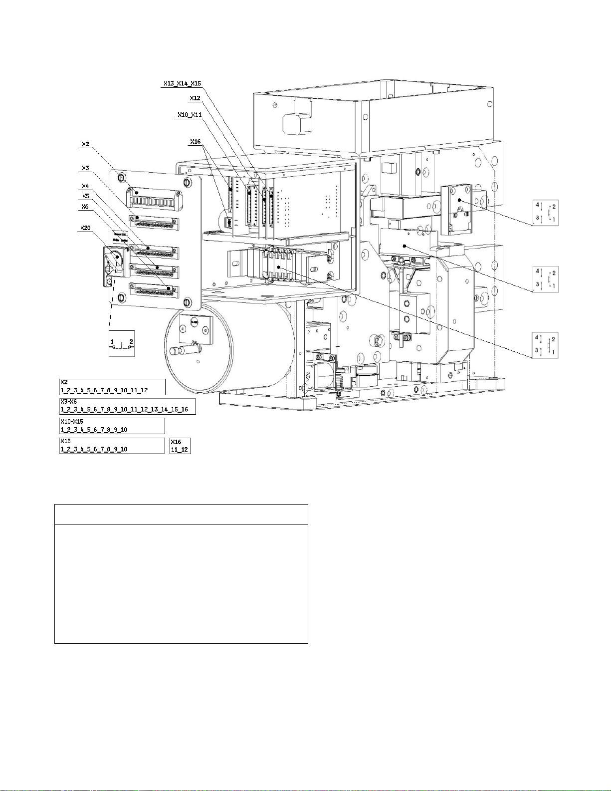
4.1 Controls layout
Description
Designation
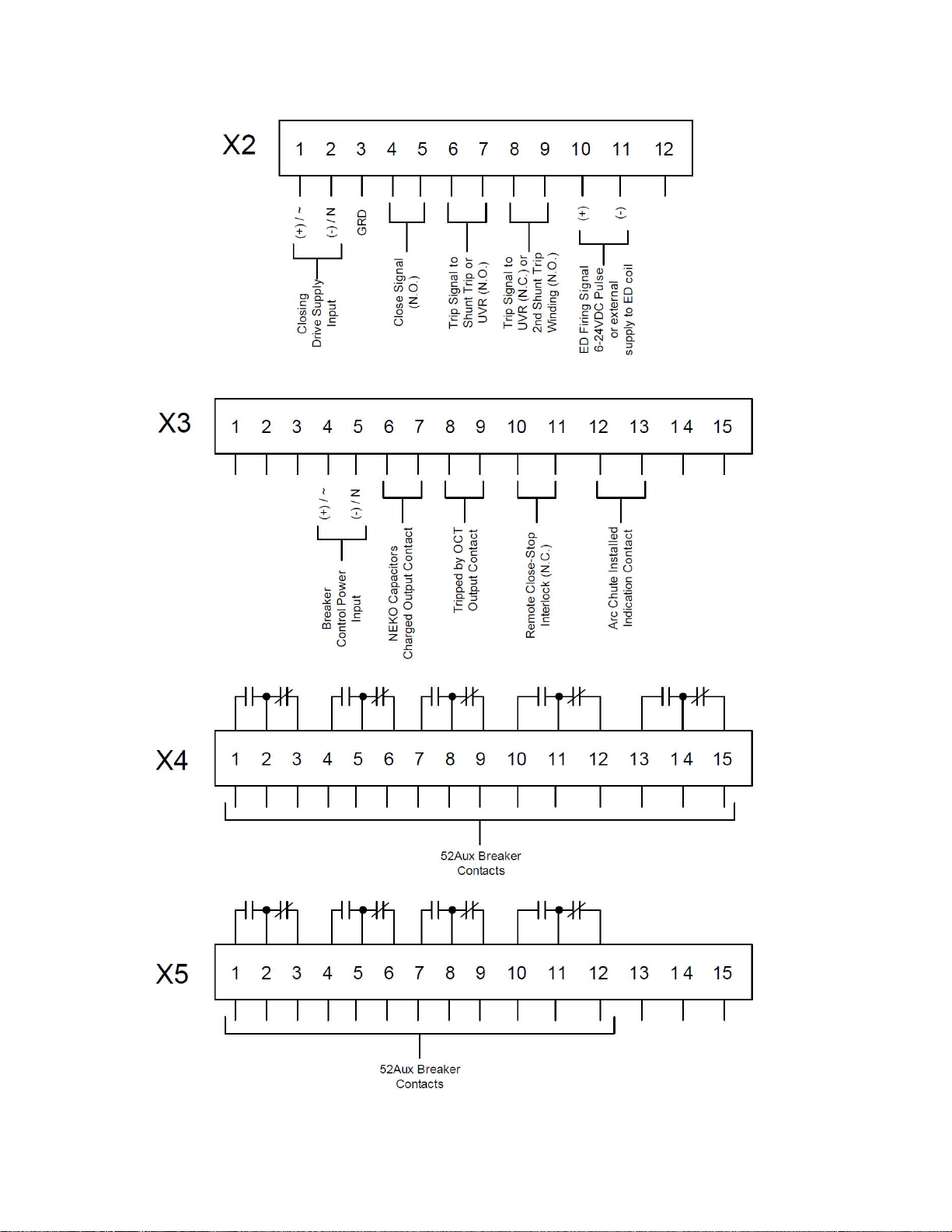
X2 1.Connector: Auxiliary- and control circuits
X3 2.Connector: Auxiliary- and control circuits
X4 3.Connector: Auxiliary contacts HS1...HS5
X5 4.Connector: Auxiliary contacts HS6...HS8
X10 Control board: Voltage converter
X12 Control board: SU control unit
X13 Control board: Shunt trip control unit
X14 Control board: Zero voltage release
X16 Control board: NEKO control unit for ED coil control
X20 UL interlock
2011-03-14 S47183De rev.01 Design and specifications are subject to change without notice 15
4.2 External connections to the breaker
Fig. 21 Typical terminals wiring system, external customer connections.
16 Design and specifications are subject to change without notice S47183De rev.02 2011-03-14
4.3 Standard Wiring Diagrams
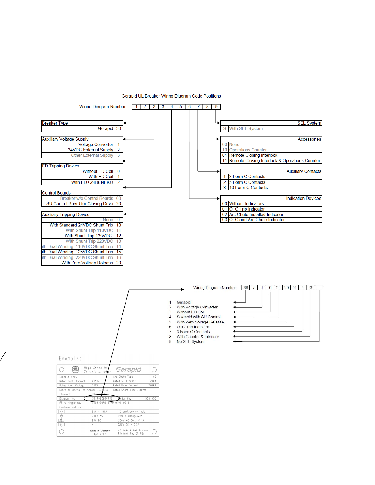
4.3.1 Wiring Code Positions
The internal wiring for Gerapid breakers is composed of several typical diagrams, for such components as tripping devices and
indicators. These basic diagrams are shown on the following pages. The power circuit is not shown for clarity. Using the key
numbers and codes shown below, the complete wiring diagram number can be obtained or deciphered. Gray shaded options are
not available of UL Listed breakers.
Note: Some special, non-standard circuit requirements may not comply with the wiring diagram coding below. In such cases, the
diagram will be assigned a unique number, for example 36/0033. For breaker with special diagrams, a copy of the special diagram is
shipped with the breaker.
Fig. 22 Example of code on the nameplate.
2011-03-14 S47183De rev.01 Design and specifications are subject to change without notice 17
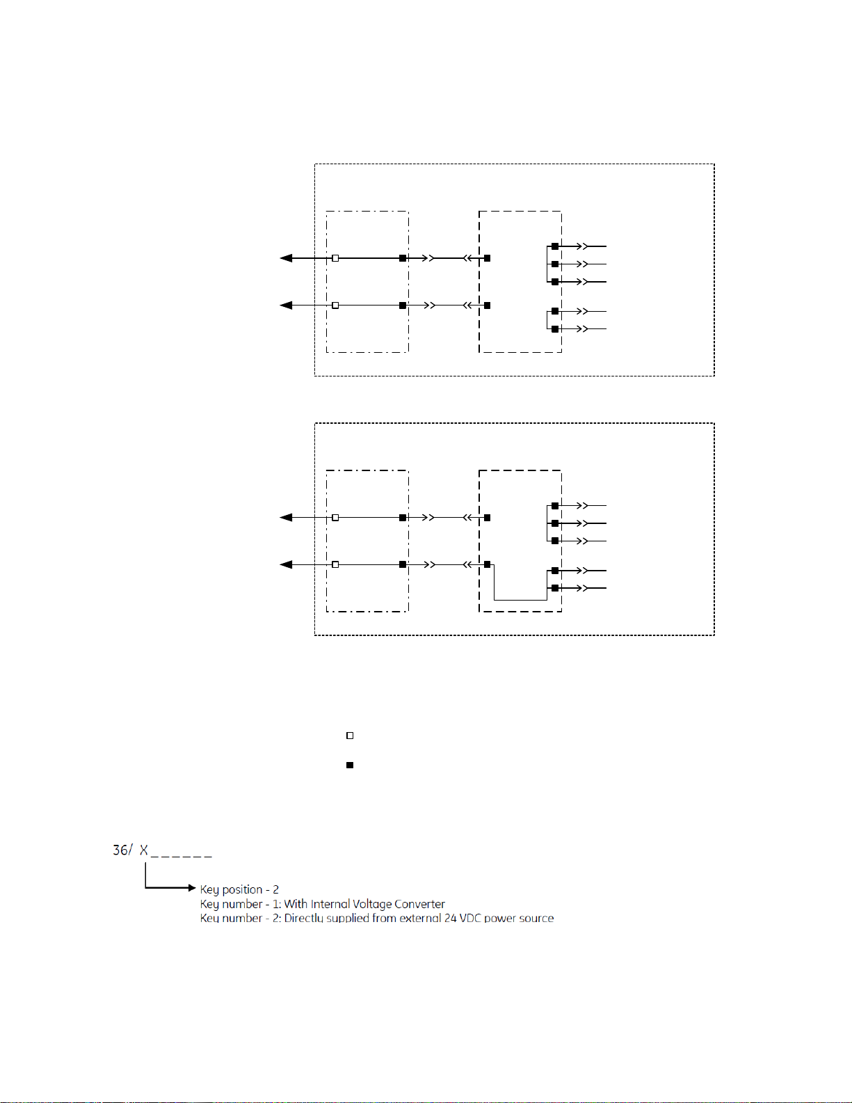
4.3.2 Breaker Internal Control Power Supply
Fig. 23 Supply with voltage converter or with direct external 24 V DC ±5%.
1 (+)
3 (-)
-X3
4 (+ or ~)
5 (- or N)
+24VDC +/- 2%
to other PCBs
-X10: PCB
User Supplied
Control Power
Source
115-240VAC +/- 10%
or
35-350VDC +/- 10%
8
9
10
6
7
Ground
1 (+)
3 (-)
-X3
4 (+)
5 ( - )
+24VDC +/- 2%
to other PCBs
-X11: PCB
User Supplied
Control Power
Source
24VDC +/- 5%
8
9
10
6
7
Ground
Breaker
Breaker
- User external connection point
- Factory interna l c o nn ection point
PCB - Printed Circuit Board
Breaker Internal Control Power Supply
User Supplied
Control Power
Source
115-240VAC +/- 10%
or
88-350VDC +/- 10%
Breaker Internal Control Power Supply (UL)
18 Design and specifications are subject to change without notice S47183De rev.02 2011-03-14
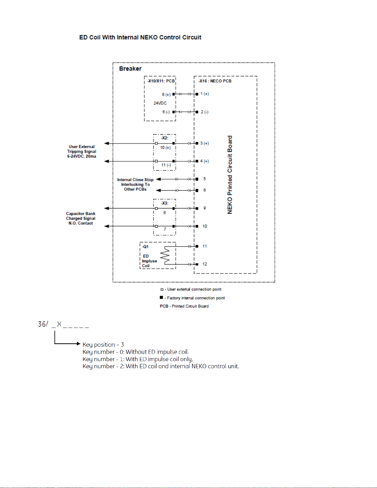
4.3.3 NEKO control circuit
Firing signal at (-X2 :10/:11) is processed by opto-coupler. Pay attention to the polarity!
Closing STOP signal is provided to lock CLOSE command, until capacitors are fully charged.
Be sure that voltage level is between DC 6 V - 24 V and there are no transient spikes (<3 ms) on firing signal. This
can lead to major defect of the NEKO control unit!
Maximum duration of the firing command must not exceed ~1 sec. Longer signal might cause NEKO failure! It is
recommended to use one of HS auxiliary contacts connected in series with firing circuit (-X2 :10). It will
automatically cut off the firing circuit after breaker opening.
Fig. 25 ED coil with internal NEKO control unit
 Loading...