


 Loading...
This book replaces the Instruction Books GEI-100332A Rev. 7.5 , GEI-100332B Rev.7.6 and GEI100332G REV. 9.2.0.
The up-to-dating is referred to SW version 9.2XX
These instructions do not purport to cover all details or variations in equipment, nor to provide every possible contingency to be met during installation, operation, and maintenance. If further information is desired or if particular problems arise that are not covered sufficiently for the purchaser’s purpose, the matter should be referred to GE Consumer & Industrial.
This document contains proprietary information of General Electric Company, USA and is furnished to its customer solely to assist that customer in the installation, testing, operation, and/or maintenance of the equipment described. This document shall not be reproduced in whole or in part nor shall its contents be disclosed to any third party without the written approval of GE Consumer & Industrial.
© 2009 by General Electric Company, USA. All rights reserved.
DV-300 Adjustable Speed Drives |
|
Table of Contents |
|
SAFETY SYMBOL LEGEND................................................................................................... |
XIV |
BLOCK DIAGRAM LEGEND................................................................................................... |
XIV |
1 - Safety Precautions - Precautions de securité............................................ |
1 |
2 - Description, Component Identification and Specifications.................... |
1 |
2.1 General.......................................................................................................................................... |
1 |
Functions and features (Overview).......................................................................................... |
3 |
2.2 Upon Delivery Inspection Procedures.................................................................................... |
4 |
Storage, Transport................................................................................................................... |
4 |
2.2.1 Device setting.................................................................................................................... |
4 |
2.3 Drive Keypad Description........................................................................................................... |
6 |
Keypad........................................................................................................................................ |
6 |
LEDs............................................................................................................................................ |
7 |
2.4 Specifications............................................................................................................................... |
8 |
2.4.1 Standards........................................................................................................................... |
8 |
2.4.2 AC Input............................................................................................................................. |
8 |
2.4.3 Output ........................................................................................................................................................................ |
10 |
Output current....................................................................................................................... |
10 |
Armature circuit.................................................................................................................... |
10 |
Field circuit........................................................................................................................... |
11 |
Output voltage....................................................................................................................... |
12 |
Armature circuit.................................................................................................................... |
12 |
Field circuit........................................................................................................................... |
12 |
2.4.4 Control section................................................................................................................. |
13 |
2.4.5 Accuracy.......................................................................................................................... |
14 |
2.5 Dimension and weights........................................................................................................... |
15 |
2.6 Watt Loss.................................................................................................................................... |
18 |
2.7 Motors, encoder, tachometer............................................................................................... |
19 |
2.7.1 Motors............................................................................................................................. |
19 |
2.7.2 Encoder / Tachometer...................................................................................................... |
20 |
3 - Installation Guidelines....................................................................................... |
1 |
3.1 Permissible Ambient Condition................................................................................................ |
1 |
3.2 Disposal of the Device................................................................................................................ |
2 |
3.3 Installation, Mounting Clearance......................................................................................... |
2 |
Mounting the device............................................................................................................... |
2 |
4 - Wiring Procedures................................................................................................ |
1 |
4.1 Removing the front cover........................................................................................................ |
1 |
—————— TABLE OF CONTENTS —————— |
I |
GEI-100332Ga |
|
Terminal Assignments/Cable Sections.................................................................................... |
1 |
4.2 Wiring the Drive........................................................................................................................... |
1 |
4.3 Power Section.............................................................................................................................. |
2 |
4.4 Regulation Section .................................................................................................................... |
6 |
4.4.1 R-TPD32-GE Regulation Card.............................................................................................. |
6 |
4.5 Serial Interface......................................................................................................................... |
12 |
4.5.1 Description....................................................................................................................... |
12 |
4.5.2 RS485 serial interface connector description.................................................................. |
13 |
4.6 Input/Output expansion card 6KCV300TBO........................................................................... |
13 |
4.6.1 Assignment of the plug-in terminal strip (terminals 1...15) for Option Card 6KCV300TBO...... |
14 |
4.6.2 Fitting the option card...................................................................................................... |
15 |
4.7 Digital encoder interface 6KDV300DES................................................................................. |
16 |
4.7.1 Description....................................................................................................................... |
16 |
4.7.2 Terminal Assignment....................................................................................................... |
17 |
4.8 Standard Connection Diagrams........................................................................................... |
18 |
4.9 Circuit Protection..................................................................................................................... |
23 |
4.9.1 Fuses............................................................................................................................... |
23 |
4.9.2 Fuses selection when the Overload function is activated................................................. |
26 |
4.9.3 Internal Fuses................................................................................................................... |
27 |
4.9.4 AC input contactors......................................................................................................... |
28 |
4.9.5 Control power protection................................................................................................. |
28 |
4.10 Reactors / Filters.................................................................................................................... |
29 |
4.10.1 AC input choke............................................................................................................... |
29 |
4.10.2 Interference suppression filters...................................................................................... |
30 |
4.11 Engineering notes................................................................................................................... |
31 |
Potentials of the regulator section......................................................................................... |
31 |
External devices.................................................................................................................... |
32 |
Connection cables................................................................................................................. |
32 |
5 - Converter Operation............................................................................................ |
1 |
5.1 Keypad............................................................................................................................................. |
1 |
5.1.1 LEDs.................................................................................................................................. |
1 |
5.1.2 Moving inside a menu........................................................................................................ |
2 |
5.1.3 Displaying parameters....................................................................................................... |
2 |
5.1.4. Changing / Saving parameters / Password........................................................................ |
3 |
Changing numerical values and text........................................................................................ |
3 |
Selection from predefined values............................................................................................ |
4 |
Autotuning of Analog input..................................................................................................... |
4 |
Parameters Saving.................................................................................................................. |
5 |
Entering a password............................................................................................................... |
5 |
II |
—————— TABLE OF CONTENTS —————— |
DV-300 Adjustable Speed Drives |
|
General unlocking of the password......................................................................................... |
6 |
5.1.5 Operating the drive via the Keypad.................................................................................... |
6 |
5.1.5.1 Starting and stopping the drive................................................................................... |
7 |
Enabling the converter............................................................................................................ |
7 |
Disabling the converter........................................................................................................... |
7 |
Start / Stop.............................................................................................................................. |
7 |
5.1.5.2 Failure register / Acknowledging alarms..................................................................... |
8 |
Clearing the failure register..................................................................................................... |
8 |
Acknowledging a failure alarm................................................................................................ |
9 |
Acknowledging when several failure alarms occur at the same time...................................... |
9 |
5.1.5.3 Motor potentiometer function..................................................................................... |
9 |
Acceleration, Deceleration...................................................................................................... |
9 |
Changing rotation direction................................................................................................... |
10 |
Resetting the speed reference value..................................................................................... |
10 |
5.1.5.4. Jog function............................................................................................................. |
10 |
5.2. Menu Structure....................................................................................................................... |
11 |
5.3 Commissioning........................................................................................................................... |
35 |
5.3.1 Setting jumpers and switch............................................................................................. |
35 |
5.3.2 Checking the wiring and the auxiliary voltages................................................................ |
36 |
5.3.3 Basic settings of the converter........................................................................................ |
36 |
5.3.4 START UP procedures...................................................................................................... |
37 |
Motor data ........................................................................................................................... |
37 |
Limits ................................................................................................................................... |
38 |
Speed feedback setting......................................................................................................... |
38 |
Alarms.................................................................................................................................. |
38 |
Overload control ................................................................................................................... |
38 |
Analog inputs 1, 2 and 3...................................................................................................... |
38 |
5.3.5 Drive tuning...................................................................................................................... |
39 |
5.3.5.1 Self tuning of the current regulator ........................................................................... |
39 |
5.3.5.1.1 Checking current regulator performance using parameter Eint............................... |
40 |
5.3.5.2 Self tuning of the speed regulator ............................................................................ |
40 |
5.3.5.3 Field converter.......................................................................................................... |
42 |
Selection of the functioning system...................................................................................... |
42 |
Setting the rated field current................................................................................................ |
42 |
Flux current min/max............................................................................................................ |
43 |
5.3.6 Manual tuning of the regulators....................................................................................... |
43 |
Using the Test generator....................................................................................................... |
43 |
Manual tuning of speed regulator.......................................................................................... |
44 |
Manual tuning of field current regulator................................................................................ |
45 |
Voltage regulator in the field converter.................................................................................. |
47 |
5.3.7 Others tuning .................................................................................................................. |
49 |
—————— TABLE OF CONTENTS —————— |
III |
|
GEI-100332Ga |
|
|
Flux / if curve tuning (Flux / if curve)..................................................................................... |
49 |
|
Speed-up function................................................................................................................. |
51 |
|
Setting of the speed zero logic.............................................................................................. |
51 |
|
Adaptive of the speed regulator............................................................................................ |
52 |
|
6 - Function Description........................................................................................... |
1 |
|
Functions and parameters....................................................................................................... |
1 |
|
Explanation of parameter tables.............................................................................................. |
2 |
|
6.1 Enables.......................................................................................................................................... |
3 |
|
6.1.1 Enable drive....................................................................................................................... |
4 |
|
6.1.2 Start / Stop........................................................................................................................ |
5 |
|
6.1.3 Fast stop............................................................................................................................ |
6 |
|
6.1.4 Quick Stop......................................................................................................................... |
7 |
|
6.1.5 External fault...................................................................................................................... |
7 |
|
6.2 BASIC START UP MENUS................................................................................................................. |
8 |
|
DRIVE STATUS........................................................................................................................ |
8 |
|
START UP................................................................................................................................ |
8 |
|
First basic setting.................................................................................................................... |
8 |
|
Motor data.............................................................................................................................. |
8 |
|
Limits...................................................................................................................................... |
9 |
|
Speed feedback....................................................................................................................... |
9 |
|
Alarms.................................................................................................................................... |
9 |
|
Overload control...................................................................................................................... |
9 |
|
Analog inputs........................................................................................................................ |
10 |
|
Self tuning of current regulator.............................................................................................. |
10 |
|
Self tuning of speed regulator............................................................................................... |
10 |
|
Final operation...................................................................................................................... |
11 |
|
TUNING................................................................................................................................. |
11 |
|
Current self tuning................................................................................................................. |
11 |
|
Speed self tune..................................................................................................................... |
11 |
|
Manual tuning of speed regulator, field regulator and voltage regulator................................ |
11 |
|
6.3 Monitor........................................................................................................................................ |
12 |
|
6.4 Input Variables.......................................................................................................................... |
16 |
|
6.4.1 Ramp ref.......................................................................................................................... |
17 |
|
6.4.2 Speed ref......................................................................................................................... |
18 |
|
6.4.3 Torque current reference (T current ref)........................................................................... |
20 |
|
6.5 Limits............................................................................................................................................ |
21 |
|
6.5.1 Speed Limits.................................................................................................................... |
21 |
|
6.5.2. Armature current limits (Current limits).......................................................................... |
23 |
|
6.5.3 Flux limits........................................................................................................................ |
25 |
|
6.6 Ramp............................................................................................................................................. |
26 |
|
6.6.1 Acceleration, Deceleration, Quick Stop............................................................................ |
27 |
IV |
—————— TABLE OF CONTENTS —————— |
|
DV-300 Adjustable Speed Drives |
|
6.6.2 Ramp shape and control commands................................................................................ |
28 |
6.7 Speed Regulation (SPEED REGULAT)......................................................................................... |
31 |
6.7.1 Speed regulator................................................................................................................ |
32 |
6.7.1.1 Self tuning of Speed regulator.................................................................................. |
33 |
6.7.2 Spd zero logic................................................................................................................... |
34 |
6.7.3 Speed up.......................................................................................................................... |
35 |
6.7.4. Droop function................................................................................................................ |
36 |
6.7.5 Inertia/Loss compensation............................................................................................... |
38 |
6.8 Current regulation (Current regulAT)............................................................................... |
39 |
6.9 Flux REGULATION......................................................................................................................... |
41 |
6.10 Reg Parameters....................................................................................................................... |
44 |
6.11 Configuration.......................................................................................................................... |
46 |
6.11.1 Operating mode selection.............................................................................................. |
46 |
6.11.2 Speed base value, Full load current................................................................................ |
48 |
6.11.3 Configuration of the OK relay (Terminals 35,36)............................................................. |
48 |
6.11.4. Configuration of the speed feedback circuit.................................................................. |
49 |
Ind store ctrl parameter [92]................................................................................................. |
52 |
Index storing parameter [13]................................................................................................. |
53 |
6.11.5 “Standard / American” selection, Software Version....................................................... |
53 |
6.11.6. Dimension factor, Face value fator................................................................................ |
54 |
6.11.7. Programmable alarms................................................................................................... |
56 |
6.11.8 Address for bus operation.............................................................................................. |
62 |
6.11.9 Password....................................................................................................................... |
63 |
6.12 I/O Config................................................................................................................................... |
64 |
6.12.1 Analog Ouputs............................................................................................................... |
65 |
6.12.2 Analog Inputs................................................................................................................. |
67 |
6.12.3 Digital Outputs............................................................................................................... |
73 |
6.12.4 Digital Inputs.................................................................................................................. |
76 |
6.12.5 Speed reference from encoder input (Tach follower function)........................................ |
79 |
6.13 Additional speed functions (add Speed Funct)............................................................... |
81 |
6.13.1 Auto capture.................................................................................................................. |
81 |
6.13.2 Adptive spd reg.............................................................................................................. |
81 |
6.13.3 Speed control................................................................................................................. |
84 |
6.13.4 Speed zero..................................................................................................................... |
86 |
6.14 Functions.................................................................................................................................. |
87 |
6.14.1 Motorpotentiometer....................................................................................................... |
87 |
6.14.2 Jog function................................................................................................................... |
89 |
6.14.3 Multi speed function...................................................................................................... |
91 |
—————— TABLE OF CONTENTS —————— |
V |
GEI-100332Ga |
|
6.14.4 Multi ramp function........................................................................................................ |
94 |
6.14.5 Speed Draw function...................................................................................................... |
98 |
6.14.6 Overload control........................................................................................................... |
100 |
6.14.7 Stop control................................................................................................................. |
121 |
6.14.8 Brake control................................................................................................................ |
123 |
6.14.9 Current limitation according to the speed (I/n curve)................................................... |
126 |
6.15 SPEC FUNCTIONS....................................................................................................................... |
127 |
6.15.1 Test generator.............................................................................................................. |
127 |
6.15.2 Saving parameters, loading default factory settings, life time...................................... |
128 |
6.15.3 Failure Register............................................................................................................ |
129 |
6.15.4. Signal adaptation........................................................................................................ |
130 |
6.15.5 Pads............................................................................................................................. |
132 |
6.16 Options..................................................................................................................................... |
135 |
6.16.1 Option 1....................................................................................................................... |
135 |
6.16.2 Option 2....................................................................................................................... |
135 |
6.16.3 PID Functon.................................................................................................................. |
137 |
6.16.3.1 General.................................................................................................................. |
138 |
6.16.3.2 Inputs / Outputs.................................................................................................... |
138 |
6.16.3.3 Feed - Forward...................................................................................................... |
139 |
6.16.3.4 PID function.......................................................................................................... |
141 |
6.16.3.5 Proportional - integral block................................................................................... |
143 |
6.16.3.6 Proportional - Derivative control block................................................................... |
147 |
6.16.3.7 Output reference................................................................................................... |
149 |
6.16.3.8 Function of calculation for Initial diameter ............................................................ |
151 |
6.16.3.9 Procedure of calculation for initial diameter.......................................................... |
153 |
6.16.3.10 Examples of application...................................................................................... |
154 |
6.16.3.11 Generic PID......................................................................................................... |
171 |
6.16.3.12 Application note................................................................................................. |
173 |
6.17 Torque Winder function..................................................................................................... |
176 |
6.17.1 Diameter calculation.................................................................................................... |
177 |
6.17.2 Torque calculation........................................................................................................ |
181 |
6.17.2.1 Compensations and closing of the tension loop.................................................... |
182 |
6.17.2.2 Taper function....................................................................................................... |
185 |
6.17.3 Calculation of the speed reference............................................................................... |
186 |
6.17.4 Typical connection diagrams........................................................................................ |
191 |
6.17.5 Control logic................................................................................................................. |
195 |
Diameter initialization.......................................................................................................... |
195 |
Initial phase......................................................................................................................... |
195 |
Automatic switching........................................................................................................... |
196 |
Reel stop............................................................................................................................. |
196 |
VI |
—————— TABLE OF CONTENTS —————— |
DV-300 Adjustable Speed Drives |
|
Jog function........................................................................................................................ |
197 |
6.17.6 Application example..................................................................................................... |
198 |
Provisions........................................................................................................................... |
208 |
1. Drive used as a winder – winding side = up.................................................................. |
208 |
2. Drive used as a winder – winding side = down............................................................. |
209 |
3. Drive used as an unwinder – unwinding side = up......................................................... |
209 |
4. Drive used as an unwinder – unwinding side = down.................................................... |
210 |
6.17.7 Block diagram.............................................................................................................. |
211 |
6.18 Drivecom.................................................................................................................................. |
215 |
6.18.1 Control word, status word, malfunction code.............................................................. |
215 |
6.18.2 Speed........................................................................................................................... |
216 |
6.18.3 Speed limitation........................................................................................................... |
217 |
6.18.4 Acceleration / Deceleration.......................................................................................... |
218 |
6.18.5 Factor function............................................................................................................. |
219 |
6.19 SERVICE...................................................................................................................................... |
220 |
7- Maintenance............................................................................................................ |
1 |
7.1 Care................................................................................................................................................ |
1 |
7.2 Service............................................................................................................................................ |
1 |
7.3 Repairs........................................................................................................................................... |
1 |
7.4 Customer Service........................................................................................................................ |
1 |
8 - Troubleshooting.................................................................................................... |
1 |
Failure alarms in the keypad display ....................................................................................... |
1 |
Other faults............................................................................................................................. |
5 |
9 - Block Diagram........................................................................................................ |
1 |
9.1 Control Block Diagrams........................................................................................................... |
1 |
DV-300 Converter Overview.................................................................................................... |
1 |
Digital Inputs /Outputs & Mapping Standard and TBO cards................................................... |
2 |
Analog Inputs/Outputs & Mapping.......................................................................................... |
3 |
Speed Reference Generation................................................................................................... |
4 |
Ramp reference Block............................................................................................................. |
5 |
Speed / Current Regulator Overview....................................................................................... |
6 |
Speed Feedback setting.......................................................................................................... |
7 |
Speed regulator....................................................................................................................... |
8 |
Speed regulator PI part............................................................................................................ |
9 |
Speed adaptive and Speed zero logic.................................................................................... |
10 |
Current regulator................................................................................................................... |
11 |
Field current regulator........................................................................................................... |
12 |
Motor parameters................................................................................................................. |
13 |
Start and Stop management................................................................................................. |
14 |
Droop compensation............................................................................................................. |
15 |
—————— TABLE OF CONTENTS —————— |
VII |
|
GEI-100332Ga |
|
|
Inertia / Loss compensation.................................................................................................. |
16 |
|
Speed Threshold / Speed control........................................................................................... |
17 |
|
PID function........................................................................................................................... |
18 |
|
Functions.............................................................................................................................. |
19 |
|
LINKS Function...................................................................................................................... |
20 |
|
PAD parameters.................................................................................................................... |
21 |
|
Taper Current Limits.............................................................................................................. |
22 |
|
Dimension factor - Face value factor..................................................................................... |
23 |
|
Test Generator....................................................................................................................... |
24 |
|
JOG function......................................................................................................................... |
25 |
|
Multispeed............................................................................................................................ |
26 |
|
Motor potentiometer............................................................................................................. |
27 |
|
Alarm mapping...................................................................................................................... |
28 |
9.2 Power Circuit Block Diagrams.............................................................................................. |
29 |
|
9.3 Regulation Card........................................................................................................................ |
35 |
|
10 - Parameter Lists.................................................................................................... |
1 |
|
10.1 Complete main menu list........................................................................................................ |
1 |
|
10.2 Numerical List.......................................................................................................................... |
37 |
|
10.3 Parameters in Alphabetical order.................................................................................... |
63 |
|
10.4 List of High priority parameters......................................................................................... |
81 |
|
11 - Replacement Parts.............................................................................................. |
1 |
|
11.1 Hardware configuration (cards / dip switches / jumpers).......................................... |
1 |
|
11.2. R-TPD32-GE REGULATION card.................................................................................................. |
2 |
|
11.3 FIR1-... |
power/driver cardS.................................................................................................... |
3 |
11.4 FIR2-... |
power/driver card...................................................................................................... |
4 |
11.6 PBB power connection card................................................................................................. |
6 |
|
11.7 PFC1-32 field converter.......................................................................................................... |
6 |
|
11.8 PFC2-31 field converter.......................................................................................................... |
7 |
|
11.9 SN-FC field snubber................................................................................................................. |
7 |
|
11.10 SN4-31, SN5-31 snubber........................................................................................................... |
8 |
|
11.11 SW1-31 power supply card................................................................................................... |
8 |
|
11.12 SW2-32 power supply card.................................................................................................. |
9 |
|
11.13 FL-31 filter................................................................................................................................. |
9 |
|
11.14 CN3 connection card........................................................................................................... |
10 |
|
11.15 I/O option card 6KCV300TBO................................................................................................. |
10 |
|
VIII |
—————— TABLE OF CONTENTS —————— |
|
DV-300 Adjustable Speed Drives |
|
List of Figures |
|
|
1 - Safety Precautions - Precautions de securité............................................ |
1 |
|
2 - Description, Component Identification and Specifications.................... |
1 |
|
Fig 2.1: Base diagram of a converter......................................................................................................................................... |
|
1 |
Fig. 2.5.1: Drive dimensions for 20 A ... |
185 A sizes (form 1).................................................................................................. |
15 |
Fig. 2.5.2: Drive dimensions for 280 A ... |
650 A sizes (form 2)................................................................................................ |
16 |
Fig. 2.5.3: Drive dimensions for 770 A ... |
1050 A sizes (form 3).............................................................................................. |
17 |
3 - Installation Guidelines....................................................................................... |
1 |
|
Figure 3.3.1: max Angle of Inclination........................................................................................................................................ |
|
2 |
Figure 3.3.2: Mounting Clearance............................................................................................................................................. |
|
3 |
4 - Wiring Procedures................................................................................................ |
|
1 |
Figure 4.1.1: Removing the Front Panel..................................................................................................................................... |
|
1 |
Figure 4.4.1: R-TPD32-GE regulation card................................................................................................................................. |
6 |
|
Figure 4.4.2: Disposition of terminals from 1 to 42..................................................................................................................... |
9 |
|
Figure 4.5.1.1: RS485 serial interface...................................................................................................................................... |
|
12 |
Figure 4.6.2.1: Installing the option card.................................................................................................................................. |
|
15 |
Figure 4.7.1.1: 6KDV300DES card.......................................................................................................................................... |
|
16 |
Figure 4.8.1:Control sequencing.............................................................................................................................................. |
|
18 |
Figure 4.8.2: Example for relay interface................................................................................................................................. |
19 |
|
Figure 4.8.3: Typical connections............................................................................................................................................ |
|
20 |
Figure 4.8.4: Encoder and Tachometer Connections............................................................................................................... |
21 |
|
Figure 4.8.5: Programmable Inputs/outputs (option 6KCV300TBO) with relay and contacts.................................................... |
21 |
|
Figure 4.8.6: Programmable Inputs/outputs with PLC.............................................................................................................. |
22 |
|
Figure 4.8.7: 6KCV300DES connection.................................................................................................................................... |
|
22 |
Figure 4.9.1.1: Position of the super fast fuses....................................................................................................................... |
23 |
|
Figure 4.11.1: Potentials of the regulator section.................................................................................................................... |
31 |
|
5 - Converter Operation............................................................................................ |
|
1 |
Figure 5.1.2.1: Moving inside a menu....................................................................................................................................... |
|
2 |
Figure 5.3.6.1: Above: Actual spd; Below: Motor current. Speed P too low. ........................................................................... |
45 |
|
Figure 5.3.6.3: Above: Actual spd; Below: Motor current. Speed I too high. ........................................................................... |
45 |
|
Figure 5.3.6.2: Above: Actual spd; Below: Motor current. Speed P too high........................................................................... |
45 |
|
Figure 5.3.6.4: Above: Actual spd; Below: Motor current. Speed P and Speed I set correctly................................................. |
45 |
|
Figure 5.3.6.5: Above: Flux reference; Below: Flux current. The regulator behavior is not good. Jumps are due to field chan- |
||
ging.................................................................................................................................................................................... |
|
46 |
Figure 5.3.6.7: Above: Flux reference; Below: Flux current. The increment in the field current has no jump. Variation compa- |
||
red to Fig. 4.5.7: Increase of Flux P from 2 to 10%. Flux I = 5%........................................................................................ |
46 |
|
Figure 5.3.6.6: Above: Flux reference; Below: Flux current. The reduction of the field current depends on the field time con- |
|
|
stant. The reg has no influence.......................................................................................................................................... |
|
46 |
Figure 5.3.6.8: Above: Flux; Below: Output voltage. After a speed change the field current (Flux) has some jumps. Voltage P |
||
= 10%, Voltage I = 80%................................................................................................................................................... |
|
48 |
Figure 5.3.6.10: Above: Flux; Below: Output voltage. After a short transient, the field current and armature voltage are con- |
|
|
stant. Voltage P = 40%, Voltage I = 50%......................................................................................................................... |
48 |
|
Figure 5.3.6.9: Above: Flux; Below: Output voltage. The gain is too low. The armature voltage increases. Voltage P = 3%, |
|
|
Voltage I = 5%.................................................................................................................................................................. |
|
48 |
Figure 5.3.7.1: Curve convertion flux/current......................................................................................................................... |
49 |
|
Figure 5.3.7.2: Blocks diagrams of field current regulator....................................................................................................... |
50 |
|
Figure 5.3.7.3: Above: Actual spd; Below: Motor current jumps with the speed changes due to a high moment of inertia. The |
||
function Speed-up is not active.......................................................................................................................................... |
|
51 |
Figure 5.3.7.4: Above: Actual spd; Below: Motor current. The same drive with Speed -up function active............................. |
51 |
|
6 - Function Description........................................................................................... |
|
1 |
—————— TABLE OF CONTENTS —————— |
IX |
|
GEI-100332Ga |
|
|
Figure 6.1.1 Enables via |
potential free contacts and PLC.......................................................................................................... |
|
3 |
Figure 6.4.1.1: Ramp references.............................................................................................................................................. |
|
17 |
|
Figure 6.4.2.1: Speed reference............................................................................................................................................... |
|
19 |
|
Figure 6.4.3.1: Torque current reference.................................................................................................................................. |
|
20 |
|
Figure 6.6.1 : Ramp circuit....................................................................................................................................................... |
|
26 |
|
Figure 6.6.1.1: Accel, decel and Quick stop............................................................................................................................. |
|
27 |
|
Figure 6.6.2.1: Ramp shape..................................................................................................................................................... |
|
29 |
|
Figure 6.6.2.2: Ramp delay...................................................................................................................................................... |
|
29 |
|
Figure 6.6.2.3: Ramp control.................................................................................................................................................... |
|
30 |
|
Figure 6.7.1: Speed regulation................................................................................................................................................. |
|
31 |
|
Figure 6.7.2.1: Speed zero logic.............................................................................................................................................. |
|
34 |
|
Figure 6.7.4.1: Droop compensation........................................................................................................................................ |
|
36 |
|
Figure 6.7.4.2: Droop function example................................................................................................................................... |
|
37 |
|
Figure 6.7.5.1: Inertia/Loss compensation.............................................................................................................................. |
|
38 |
|
Figure 6.8.1: Torque current regulaton..................................................................................................................................... |
|
39 |
|
Figure 6.9.1: Motor control...................................................................................................................................................... |
|
41 |
|
Figure 6.11.4.1: Speed feedback............................................................................................................................................. |
|
50 |
|
Figure 6.11.4.2: Allowed area for Encoder 2 pulses and Motor max speed............................................................................. |
51 |
||
Figure 6.11.6.1: Calculation using dimension and face value factors....................................................................................... |
55 |
||
Figure 6.11.7.1: Drive enabling sequence: Main command = |
Terminals.............................................................................. |
61 |
|
Figure 6.11.7.2 Drive enabling sequence: Main command = |
Digital................................................................................... |
61 |
|
Figure 6.12.1: Arrangement of the programmable I/O............................................................................................................. |
|
64 |
|
Figure 6.12.1.1: Option card, analog output blocks.................................................................................................................. |
|
66 |
|
Figure 6.12.2.1: Analog input................................................................................................................................................... |
|
71 |
|
Figure 6.12.2.2: Analog Input 1 window comparator.............................................................................................................. |
|
72 |
|
Figure 6.12.3.1: Digital outputs................................................................................................................................................ |
|
74 |
|
Figure 6.12.4.1: Digital inputs.................................................................................................................................................. |
|
76 |
|
Figure 6.12.5.1: Tach follower.................................................................................................................................................. |
|
79 |
|
Figure 6.12.5.2: Example of application of the encoder reference........................................................................................... |
80 |
||
Figure 6.13.2.1: Adaptive of the speed regulator..................................................................................................................... |
|
83 |
|
Figure 6.13.3.1: “Speed threshold” (up) and “Set speed” (down) messages.......................................................................... |
85 |
||
Figure 6.13.4.1: Speed zero..................................................................................................................................................... |
|
86 |
|
Figure 6.14.1.1: Motor potentiometer...................................................................................................................................... |
|
88 |
|
Figure 6.14.2.1: Example of external activation in Jog mode................................................................................................... |
|
90 |
|
Figure 6.14.3.1: Selection of different references via terminals............................................................................................... |
|
91 |
|
Figure 6.14.3.2: Multi speed function...................................................................................................................................... |
|
93 |
|
Figure 6.14.4.1: Multi ramp selection via terminals................................................................................................................. |
|
97 |
|
Figure 6.14.4.2: Multi ramp selection via signals..................................................................................................................... |
|
97 |
|
Figure 6.14.5.1: Speed draw block diagram........................................................................................................................... |
|
98 |
|
Figure 6.14.5.2: Rubber calender example............................................................................................................................... |
|
99 |
|
Figure 6.14.6.1: Overload control (Overload mode = curr limited)........................................................................................ |
103 |
||
Figure 6.14.6.2: Overload control (Overload mode= curr not limited)................................................................................... |
103 |
||
Figure 6.14.6.3: ExampleOperating point of drive................................................................................................................ |
|
120 |
|
Figure 6.14.7.1: Start and stop management......................................................................................................................... |
|
121 |
|
Figure 6.14.8.1: Diagram of control........................................................................................................................................ |
|
124 |
|
Figure 6.14.8.2: Brake control diagram.................................................................................................................................. |
|
125 |
|
Figure 6.14.8.1 Current limitation according to the speed...................................................................................................... |
|
126 |
|
Figure 6.15.1.1: Test generator output................................................................................................................................... |
|
127 |
|
Figure 6.15.4.1: Structure of the signal adaptation................................................................................................................ |
|
131 |
|
Figure 6.15.5.1: Bus pads...................................................................................................................................................... |
|
134 |
|
Figure 6.16.3.1: Feed-forward block description.................................................................................................................... |
|
139 |
|
Figure 6.16.3.2: PID blocks description.................................................................................................................................. |
|
141 |
|
Figure 6.16.3.3: PI block description...................................................................................................................................... |
|
143 |
|
Figure 6.16.3.4: PD block description................................................................................................................................... |
|
147 |
|
Figure 6.16.3.5: Output reference block description............................................................................................................... |
|
149 |
|
Figure 6.16.3.6: Diameter calculation block description ........................................................................................................ |
|
151 |
|
Figure 6.16.3.7: Diameter calculation.................................................................................................................................... |
|
152 |
|
X |
—————— TABLE OF CONTENTS —————— |
|
|
DV-300 Adjustable Speed Drives |
|
|
|
Figure 6.16.3.8: Nip-roll control with dancer.......................................................................................................................... |
|
|
154 |
Figure 6.16.3.9: Nip-rolls control with load cell..................................................................................................................... |
|
|
157 |
Figure 6.16.3.10: Winder/Unwinder control with dancer....................................................................................................... |
|
161 |
|
Figure 6.16.3.11: Diameter calculation.................................................................................................................................. |
|
|
165 |
Figure 6.16.3.12: Winder/unwinder control with sensor diameter......................................................................................... |
|
166 |
|
Figure 6.16.3.13: Relation between transducer signal and coil signal.................................................................................... |
|
166 |
|
Figure 6.16.3.14: Pressure control for pumps and extruder ................................................................................................... |
|
168 |
|
Figure 6.16.3.15: Example with small and large diameter...................................................................................................... |
|
173 |
|
Figure 6.16.3.16: Relation between PI I gain PID and PI I output PID.................................................................................... |
|
174 |
|
Figure 6.16.3.17: General description of the PID blocks......................................................................................................... |
|
175 |
|
Figure 6.17.1: Acceleration and deceleration indication....................................................................................................... |
|
183 |
|
Figure 6.17.2: Relation among the Taper function parameters.............................................................................................. |
|
185 |
|
Figure 6.17.3: Operative sequence of the functioning status.................................................................................................. |
|
188 |
|
Figure 6.17.4: Functioning with Jog TW enable..................................................................................................................... |
|
|
190 |
Figure 6.17.5: Winder with an automatic switch and a closed loop tension regulation.......................................................... |
|
191 |
|
Figure 6.17.6: Winder with an automatic switch and a closed loop tension regulation.......................................................... |
|
192 |
|
Figure 6.17.7: Winder with an automatic switch and a closed loop tension regulation.......................................................... |
|
193 |
|
Figure 6.17.8: Winder with an automatic switch and a closed loop tension regulation.......................................................... |
|
194 |
|
Figure 6.17.9: Initial phase with a stopped line...................................................................................................................... |
|
|
195 |
Figure 6.17.10: Automatic switching between two coils during a winding/unwinding period................................................ |
|
196 |
|
Figure 6.17.11: Coil stop after the automatic switching......................................................................................................... |
|
197 |
|
Figure 6.17.12: Jog function to prepare the machine............................................................................................................. |
|
|
197 |
Figure 6.17.13: Drive used as a winder – winding side = up................................................................................................ |
|
208 |
|
Figure 6.17.14: Drive used as a winder – winding side = down........................................................................................... |
|
209 |
|
Figure 6.17.15: Drive used as an unwinder – unwinding side = up...................................................................................... |
|
209 |
|
Figure 6.17.16: Drive used as an unwinder – unwinding side = down.................................................................................. |
|
210 |
|
Figure 6.17.4.1: Acceleration and deceleration...................................................................................................................... |
|
|
219 |
7- Maintenance............................................................................................................ |
|
|
1 |
8 - Troubleshooting.................................................................................................... |
|
|
1 |
9 - Block Diagram........................................................................................................ |
|
|
1 |
Figure 9.2.1: Circuit block diagram: 6KDV3017Q4F ... |
to 6KDV3148Q4F - 6KDV3020Q4E ... |
to 6KDV3185Q4E..................... |
29 |
Figure 9.2.2: Circuit block diagram: 6KDV3224Q4F ... |
to 6KDV3450Q4F - 6KDV3280Q4E ... |
to 6KDV3650Q4E..................... |
30 |
Figure 9.2.3: Circuit block diagram: 6KDV3560Q4F ... |
to 6KDV3850Q4F - 6KDV3770Q4E ... |
to 6KDV310HQ4E.................... |
31 |
Figure 9.2.4: Circuit block diagram: 6KDV3017Q2B ... |
to 6KDV3148Q2B - 6KDV3020Q2A ... |
to 6KDV3185Q2A................... |
32 |
Figure 9.2.5: Circuit block diagram: 6KDV3224Q2B ... |
to 6KDV3450Q2B - 6KDV3280Q2A ... |
to 6KDV3650Q2A................... |
33 |
Figure 9.2.6: Circuit block diagram: 6KDV3560Q2B ... |
to 6KDV3850Q2B - 6KDV3770Q2A ... |
to 6KDV310HQ2A................... |
34 |
10 - Parameter Lists.................................................................................................... |
|
|
1 |
11 - Replacement Parts.............................................................................................. |
|
|
1 |
—————— TABLE OF CONTENTS —————— |
XI |
GEI-100332Ga |
|
List of tables |
|
1 - Safety Precautions - Precautions de securité............................................ |
1 |
2 - Description, Component Identification and Specifications.................... |
1 |
Table 2.1.1: Converter size........................................................................................................................................................ |
2 |
Table 2.3.1: Keypad LEDs.......................................................................................................................................................... |
7 |
Table 2.4.2.1: AC input votages................................................................................................................................................. |
8 |
Table 2.4.2.2: AC input curents.................................................................................................................................................. |
9 |
Table 2.4.3.1: Output currents.................................................................................................................................................. |
10 |
Table 2.4.3.2: Field current resistors........................................................................................................................................ |
11 |
Table 2.4.3.3: Armature circuit output votages......................................................................................................................... |
12 |
Table 2.4.3.4: Field circuit output votages................................................................................................................................ |
12 |
Table 2.6.1: Power Dissipation................................................................................................................................................. |
18 |
3 - Installation Guidelines....................................................................................... |
1 |
4 - Wiring Procedures................................................................................................ |
1 |
Table 4.3.1: Terminals description.............................................................................................................................................. |
2 |
Table 4.3.2: Cable size for power terminals U, V, W, C, D, PE.................................................................................................... |
2 |
Table 4.3.3: Cable section for UL approval................................................................................................................................ |
3 |
Table 4.3.4: Wire adapter Kit and lugs suggested for UL approval........................................................................................... |
4 |
Table 4.3.5: Cable size for power field terminals U1, V1, C1, D1............................................................................................... |
5 |
Table 4.3.6: Cable size for fans, signals, thermistors and regulation supply.............................................................................. |
5 |
Table 4.4.1: LEDs on the R-TPD32-GE card............................................................................................................................... |
6 |
Table 4.4.2: Dip-switch S15 adaptation of the regulation card to the device type..................................................................... |
7 |
Table 4.4.3 : Dip-switch S4 adaptation of the tachometer feedback to the input voltage ......................................................... |
7 |
Table 4.4.4: Jumpers on the R-TPD32-GE card.......................................................................................................................... |
8 |
Table 4.4.5: Test points on Regulator card................................................................................................................................. |
8 |
Table 4.4.6 - A: Terminal Assignment (terminals from 1 to 20)................................................................................................... |
9 |
Table 4.4.6 - B: Terminal Assignment (terminals from 21 to 42).............................................................................................. |
10 |
Table 4.4.7: Cable size for fans, signals, and thermistors........................................................................................................ |
11 |
Table 4.4.8: Terminal strip for the connection of an analog tachometer................................................................................... |
11 |
Table 4.4.9: Assignment of an XE1 connector for a sinusoidal encoder................................................................................ |
11 |
Table 4.4.10: Assignment of the XE2 connector for a digital encoder...................................................................................... |
11 |
Table 4.5.2.1: Description of the XS connector for the RS485 serial interface......................................................................... |
13 |
Table 4.6.1.1: Terminal strip connections................................................................................................................................. |
14 |
Table 4.6.1.2: Cable size for terminals of the option card 6KCV300TBO.................................................................................. |
15 |
Table 4.7.2.1: Terminal assignment (Terminals 0Venc and +Venc).......................................................................................... |
17 |
Table 4.7.2.2: Permissible cable cross section on the terminals of option card 6KDV300DES.................................................. |
17 |
Table 4.7.2.3: XS1 9-pole connector........................................................................................................................................ |
17 |
Table 4.9.1.1: Recommended fuses (externally mounted)........................................................................................................ |
24 |
Table 4.9.2.1: Overload fuses................................................................................................................................................... |
26 |
Table 4.9.3.1: Internal fuses.................................................................................................................................................... |
27 |
Table 4.9.5: Control power protection...................................................................................................................................... |
28 |
Table 4.10.1.1: AC input choke............................................................................................................................................... |
30 |
5 - Converter Operation............................................................................................ |
1 |
Table 5.3.5.3.1: Tuning resistances of the field current............................................................................................................ |
43 |
6 - Function Description........................................................................................... |
1 |
Table 6.14.2.1: Multi speed function........................................................................................................................................ |
93 |
Table 6.14.4.1: Ramp selection................................................................................................................................................ |
96 |
Table 6.14.6.1: I2t derating............................................................................................................................ |
102 |
7- Maintenance............................................................................................................ |
1 |
XII |
—————— TABLE OF CONTENTS —————— |
|
|
|
DV-300 Adjustable Speed Drives |
8 |
- Troubleshooting.................................................................................................... |
1 |
|
9 |
- Block Diagram........................................................................................................ |
1 |
|
10 |
- Parameter Lists.................................................................................................... |
1 |
|
11 |
- Replacement Parts.............................................................................................. |
1 |
|
—————— TABLE OF CONTENTS —————— |
XIII |
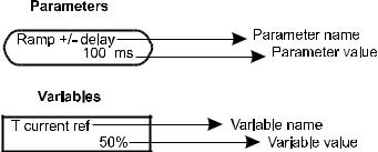
GEI-100332Ga
SAFETY SYMBOL LEGEND
Warning: Commands attention to an operating procedure, practice, condition, or statement which, if not strictly observed, could result in personai injury or death.
Caution: Commands attention to an operating procedure, practice, condition, or statement which, if not strictly observed, could result in damage or destruction of equipment.
Note: Commands attention to an operating procedure, practice, condition, or statement that must be highlighted.
BLOCK DIAGRAM LEGEND
XIV |
—————— TABLE OF CONTENTS —————— |
DV-300 Adjustable Speed Drives
1 - Safety Precautions - Precautions de securité
Attention!
According to the EEC standards the DV-300 and accessories must be used only after checking that the machine has been produced using those safety devices required by the 89/392/EEC set of rules, as far as the machine industry is concerned.
Drive systems cause mechanical motion. It is the responsibility of the user to insure that any such motion does not result in an unsafe condition. Factory provided interlocks and operating limits should not be bypassed or modified.
Selon les normes EEC, les drives DV-300 et leurs accessoires doivent être employés seulement après avoir verifié que la machine ait
été produit avec les même dispositifs de sécurité demandés par la réglementation 89/392/EEC concernant le secteur de l’industrie.
Les systèmes provoquent des mouvements mécaniques. L’utilisateur est responsable de la sécurité concernant les mouvements mécaniques. Les dispositifs de sécurité prévues par l’usine et les limitations operationelles ne doivent être dépassés ou modifiés.
Warning - Electrical Shock and Burn Hazard / ATTENTION – DÉCHARGE ÉLECTRIQUE ET Risque de brÚlure :
When using instruments such as oscilloscopes to work on live equipment, the oscilloscope’s chassis should be grounded and a differential amplifier input should be used. Care should be used in the selection of probes and leads and in the adjustment of the oscilloscope so that accurate readings may be made. See instrument manufacturer’s instruction book for proper operation and adjustments to the instrument.
Lors de l’utilisation d’instruments (par example oscilloscope) sur des systémes en marche, le chassis de l’oscilloscope doit être relié à la terre et un amplificateur différentiel devrait être utilisé en entrée.
Les sondes et conducteurs doivent être choissis avec soin pour effectuer les meilleures mesures à l’aide d’un oscilloscope.
Voir le manuel d’instruction pour une utilisation correcte des instruments.
Warning - Fire and Explosion Hazard / ATTENTION – RISQUE D’INCENDIES ET D’EXPLOSIONs:
Fires or explosions might result from mounting Drives in hazardous areas such as locations where flammable or combustible vapors or dusts are present. Drives should be installed away from hazardous areas, even if used with motors suitable for use in these locations.
L’utilisationdes drivesdans deszônesàrisques(présencedevapeursou depoussières inflammables), peut provoquerdesincendies ou des explosions. Les drives doivent être installés loin des zônes dangeureuses, et équipés de moteurs appropriés.
Warning - Strain Hazard / ATTENTION À L’ÉLÉVATION:
Improper lifting practices can cause serious or fatal injury. Lift only with adequate equipment and trained personnel.
Une élévation inappropriée peut causer des dommages sérieux ou fatals. Il doit être élevé seulement avec des moyens appropriés et par du personnel qualifié.
ATTENTION – CAS DE DECHARGE ELECTRIQUE:
Drives and motors must be ground connected according to the NEC.
Tous les moteurs et les drives doivent être mis à la terre selon le Code Electrique National ou équivalent.
Warning / ATTENTION:
Replace all covers before applying power to the Drive. Failure to do so may result in death or serious injury.
Remettre tous les capots avant de mettre sous tension le drive. Des erreurs peuvent provoquer de sérieux accidents ou même la mort.
Warning / ATTENTION:
Converters are electrical appliances for use in heavy current installations. Parts of the converter are energized during operation.
The electrical installation and the opening of the device should therefore only be carried out by qualified personnel. Improper installation of motors or converters may therefore cause the failure of the device as well as serious injury to people or material damage. Follow the instructions given in this manual and observe the local and national safety regulations applicable.
Les convertisseur sont des dispositifs électriques utilisés dans des installations industriels. Une partie des drive sont sous tension pendant l’operation. L’installation électrique et l’ouverture des drive devrait être executé uniquement par du personel qualifié. De mauvaises installations de moteurs ou de drive peuvent provoquer des dommages materiels ou blesser des personnes On doit suivir les instructions donneés dans ce manuel et observer les régles nationales de sécurité.
—————— SAFETY PRECAUTIONS —————— |
1 |
1 |
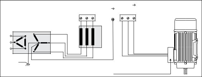
GEI-100332Ga
Warning! - Power supply and grounding / Attention ! Alimentation puissance et mise à la terre
In case of a three phase supply not symmetrical to ground, an insulation loss of one of the devices connected to the same network can cause functional problem to the drive, if the use of a wye/delta transformer is avoided.
1The drives are designed to be powered from standard three phase lines that are electrically symmetrical with respect to ground (TN or TT network).
2In case of supply with IT network, the use of delta/star transformer is mandatory, with a secondary three phase wiring referred to ground.
Please refer to the following connection sample.
Si le réseau n’est pas équilibré par rapport à la terre et qu’il n’y a pas de transformateur raingle/étoile, une mauvaise isolation d’un appareil électrique connecté au même réseau que le variateur peut lui causer des troubles de fonctionnement.
1Les variateurs sont prévus pour être alimentés par un réseau triphasé équilibré avec un régime de neutre standard (TN ou
TT).
2Si le régime de neutre est IT, nous vous recommendons d’utiliser un tranformateur triangle/étoile avec point milieu ramené à la terre
Vous pouvez trouver ci-après des exemples de câblage.
|
U |
V |
W |
PE1/ |
C |
D |
PE/ |
MainSupply |
L1 |
|
ACINPUT |
CHOKE |
|
|
|
L2 |
|
|
|
|
|||
|
|
|
|
|
|||
AC |
L3 |
|
|
|
|
|
|
|
|
|
|
|
|
|
|
|
Earth |
|
|
|
|
|
|
|
Safety |
|
|
|
|
|
|
|
ground |
|
|
|
|
|
|
|
|
|
|
All wires (including motor ground) must |
|||
|
|
|
|
be connected inside the motor terminal box |
|||
CAution / PRECAUTION:
Do not connect power supply voltage that exceeds the standard specification voltage fluctuation permissible. If excessive voltage is applied to the Drive, damage to the internal components will result.
Ne pas raccorder de tension d’alimentation dépassant la fluctuation de tension permise par les normes. Dans le cas d’une alimentation en tension excessive, des composants internes peuvent être endommagés.
Caution / PRECAUTION:
Do not operate the Drive without the ground wire connected. The motor chassis should be grounded to earth through a ground lead separate from all other equipment ground leads to prevent noise coupling.
The grounding connector shall be sized in accordance with the NEC or Canadian Electrical Code. The connection shall be made by a UL listed or CSA certified closed-loop terminal connector sized for the wire gauge involved. The connector is to be fixed using the crimp tool specified by the connector manufacturer.
Ne pas faire fonctionner le drive sans prise de terre. Le chassis du moteur doit être mis à la terre à l’aide d’un connecteur de terre separé des autres pour éviter le couplage des perturbations. Le connecteur de terre devrait être dimensionné selon la norme NEC ou le Canadian Electrical code. Le raccordement devrait être fait par un connecteur certifié et mentionné à boucle fermé par les normes CSA et UL et dimensionné pour l’épaisseur du cable correspondant. Le connecteur doit être fixé a l’aide d’un instrument de serrage specifié par le producteur du connecteur.
Caution / PRECAUTION:
Do not perform a megger test between the Drive terminals or on the control circuit terminals.
Ne pas exécuter un test megger entre les bornes du drive ou entre les bornes du circuit de contrôle.
1 |
2 |
—————— SAFETY PRECAUTIONS —————— |
DV-300 Adjustable Speed Drives
Caution / PRECAUTION:
Because the ambient temperature greatly affects Drive life and reliability, do not install the Drive in any location that exceeds the allowable temperature. Leave the ventilation cover attached for temperatures of 104° F (40° C) or below.
Étant donné que la température ambiante influe sur la vie et la fiabilité du drive, on ne devrait pas installer le drive dans des places ou la temperature permise est dépassée. Laisser le capot de ventilation en place pour températures de 104°F (40°C) ou inférieures.
Caution / PRECAUTION:
If the Drive’s Fault Alarm is activated, consult the TROUBLESHOOTING section of this instruction book, and after correcting the problem, resume operation. Do not reset the alarm automatically by external sequence, etc.
Si la Fault Alarm du drive est activée, consulter la section du manuel concernant les défauts et après avoir corrigé l’erreur, reprendre l’opération. Ne pas réiniliatiser l’alarme automatiquement par une séquence externe, etc….
Caution / PRECAUTION:
Be sure to remove the desicant dryer packet(s) when unpacking the Drive. (If not removed these packets may become lodged in the fan or air passages and cause the Drive to overheat).
Lors du déballage du drive, retirer le sachet déshydraté. (Si celui-ci n’est pas retiré, il empêche la ventilation et provoque une surchauffe du drive).
Caution / PRECAUTION:
The Drive must be mounted on a wall that is constructed of heat resistant material. While the Drive is operating, the temperature of the Drive’s cooling fins can rise to a temperature of 194° F (90°C).
Le drive doit être monté sur un mur construit avec des matériaux résistants à la chaleur. Pendant le fonctionnement du drive, la température des ailettes du dissipateur thermique peut arriver à 194°F (90°).
Note: |
The terms “Converters”, “Controller” and “Drive” are sometimes used interchangably throughout the |
|
|
industry. We will use the term “Drive” in this document |
|
|
Les mots “Convertisseur”, “Controller” et “Drive” sont interchangeables dans le domaine industriel. |
|
|
Nous utiliserons dans ce manuel seulement le mot “Drive”. |
|
|
1. |
Never open the device or covers while the AC Input power supply is switched on. Wait for at least |
|
|
one minute befor working on the terminals or inside the device. |
|
|
Ne jamais ouvrir l’appareil lorsqu’il est suns tension. Le temps minimum d’attente avant de pouvoir |
|
|
travailler sur les bornes ou bien à l’intérieur de l’drive est de 1 minute. |
|
2. |
Do not touch or damage any components when handling the device. The changing of the isolation |
|
|
gaps or the removing of the isolation and covers is not permissible. If the front plate has to be removed |
|
|
because of a room temperature higher than 40 degrees, the user has to ensure that no occasional |
|
|
contact with live parts may occur. |
|
|
Manipuler l’appareil de façon à ne pas toucher ou endommager des parties. Il n’est pas permis |
|
|
de changer les distances d’isolement ou bien d’enlever des matériaux isolants ou des capots. Si la |
|
|
plaque frontale doit être enlevée pour un fonctionnement avec la température de l’environnement |
|
|
plus haute que 40°C, l’utilisateur doit s’assurer, par des moyens opportuns, qu’aucun contact oc- |
|
|
casionnel ne puisse arriver avec les parties sous tension. |
|
3. |
Protect the device from impermissible environmental conditions (temperature, humidity, shock etc.) |
|
|
Protéger l’appareil contre des effets extérieurs non permis (température, humidité, chocs etc.). |
|
4. |
No voltage should be connected to the output of the converter (terminals C and D). The parallel |
|
|
connection of several motors on a converter output is not permissible. |
Aucune tension à la sortie du convertisseur ne peut être appliquée (bornes C et D). Il n’est pas permis d’insérer plus de convertisseurs en parallèle à la sortie ni d’effectuer une connexion directe de l’entrée avec une sortie du convertisseur.
—————— SAFETY PRECAUTIONS —————— |
3 |
1 |
GEI-100332Ga
5.When engaging a running motor, the Auto capture function (Auto capture in the ADD SPEED FUNCT menu) must be activated.
Pour reprendre des moteurs en rotation, la fonction suivante doit être activée : “Auto capture” dans le menu ADD SPEED FUNCT.
6.A capacitative load (e.g. phase compensation capacitors) should not be connected to the output of the frequency inverter (terminals C and D).
Aucune charge capacitive ne doit être connectée à la sortie du convertisseur (bornes C et D) (par exemple des condensateurs de mise en phase).
7.Always connect the converter to the protective ground (PE) via the marked connection terminals and the housing. The discharge current to earth ground is greater then 3.5 mA. EN 50178 specifies that with discharge currents greater than 3.5 mA the protective conductor ground connection must be fixed type and doubled for redundancy.
Effectuer toujours des connexions de terre (PE) par le biais des bornes et du chassis. Le courant de dispersion vers la terre est supérieur à 3,5 mA. Selon EN 50178 il faut prévoir dans ces cas une double connexion à terre.
8.Theelectricalcommissioningshouldonlybecarriedoutbyqualifiedpersonnel,whoarealsoresponsible for the provision of a suitable ground connection and a protected power supply feeder in accordance with the local and national regulations. The motor must be protected against overloads.
La mise en service électrique doit être effectuée par un personnel qualifié. Ce dernier est responsable de l’existence d’une connexion de terre adéquate et d’une protection des câbles d’alimentation selon les prescriptions locales et nationales. Le moteur doit être protégé contre la surcharge
9.No dielectric tests should be carried out on parts of the frequency inverter. A suitable measuring instrument (internal resistance of at least 10 kW/V) should be used for measuring the signal voltages.
Ilnefautpaséxécuterdetestsderigiditédiélectriquesurdespartiesduconvertisseurs.Pourmesurer les tensions, des signaux, il faut utiliser des instruments de mesure appropriés (résistance interne minimale 10 kΩ/V).
10.When the drive is stopped, but it has not been disconnected from the main via the main contactor, it is not possible to exclude the accidental movement of the motor shaft when a failure occurs.
Quand l’actionnement est arrêté, mais non débranché du réseau par le contacteur de réseau, il n’est pas possible d’exclure le mouvement accidentel de l’arbre moteur en cas de panne.
11.The user must provide overload protection for the motor, as indicated in chapter 2.7.1 and Fig. 4.8.2.
L’utilisateur dout effectuer la protection de sour-charge du moteur, comme indiqué dans le chapitre 2.7.1 et figure 4.8.2.
Warning / ATTENTION:
The UL listed equipments is suitable for use on a circuit capable of delivering not more than the rms symmetrical amperes, 500 volts maximum, shown in the table below, when protected by special purpose fuses JFHR2, Gould or Bussman, Model n. as in table 4.9.1.1 and 4.9.2.1. Fuses are internally mounted on sizes 770...1050A.
Cet appareil est adapté pour usage sur un circuit en mesure de fournir un courant de t/min symétrique de court-circuit, à un maximum de 500 V, non supérieur aux valeurs spécifiéesplus avant, si protégé par des fusibles pour usage spécial JFHR2, Gould ou Bussman, avec n° de modèle comme indiqué dans les tableaux 4.9.1.1 et 4.9.2.1. Les fusibles sont montés de façon interne sur des tailles de 770 à 1050 A.
Converter size |
Short circuit current |
17 …850 A (American sizes) |
100 kA |
20 ... 1050 A (European sizes) |
100 kA |
1 |
4 |
—————— SAFETY PRECAUTIONS —————— |
DV-300 Adjustable Speed Drives
2 - Description, Component Identification
and Specifications
2.1 General
A converter transforms the constant voltage of an existing three-phase power supply into a direct voltage, in order to regulate the speed and/or the torque of a direct current motor with a separate excitation.
The available DV-300 converters are of two types: 6KDV3...Q2 for a two quadrant functioning 6KDV3...Q4 for a four quadrant functioning
The default version of a converter includes the presence of a power supply circuit for the adjustable field; in this way the motors can operate with a mixed armature or field regulation, without adding other devices.
Each type includes three series of devices, which differ the one from the other because of the max. power supply voltage:
6KDV3...Q2A...; 6KDV3...Q4E... |
AC input supply voltage up to 400 V, 3Ph |
|||
6KDV3... |
Q2B... |
; 6KDV3... |
Q4F... |
AC input supply voltage up to 500 V, 3Ph |
6KDV3... |
Q2C... |
; 6KDV3... |
Q4G... |
AC input supply voltage up to 690 V, 3Ph |
1
AC input supply voltage:
Armature converter:
Field converter:
3 |
|
2 |
5 |
4 |
|
Fig 2.1: Base diagram of a converter
230 V, 3Ph, 50/60 Hz
400 V, 3Ph, 50/60 Hz
460 V, 3Ph, 50/60 Hz
500 V, 3Ph, 50/60 Hz
690 V, 3Ph, 50/60 Hz
Totally controlled three-phase bridge. It converts the alternating voltage into a direct voltage. (Double bridge for 6KDV3...Q4...)
Semi-controlled single-phase bridge
——— DESCRIPTION, COMPONENT IDENTIFICATION AND SPECIFICATIONS ——— |
1 |
2 |

|
GEI-100332Ga |
Programmable control section: |
Control and regulation cards of the power section. Commands, refer- |
|
ences and feedbacks are connected to them. |
Output voltage : |
Direct voltage changing from 0 to UdN |
Output rated current: |
20.... 3300 A [for a max. ambient temperature of 104°F (40°C)] |
The basic technical data of a converter are stated in the type code and on the identification nameplate.
The converters of DV-300 series are available in the following versions:
6KDV3...Q4E... |
Four quadrant converter for AC input voltage up to 400 V |
6KDV3...Q2A... |
Two quadrant converter for AC input voltage up to 400 V |
6KDV3...Q4F... |
Four quadrant converter for AC input voltage up to 500 V |
6KDV3...Q2B... |
Two quadrant converter for AC input voltage up to 500 V |
6KDV3...Q4G... |
Four quadrant converter for AC input voltage up to 690 V |
6KDV3...Q2C... |
Two quadrant converter for AC input voltage up to 690 V |
The available size are listed in the following table:
|
|
Table 2.1.1: |
Converter size |
|
|
|
|
|
|
|
|
|
|
American |
Rated DC Current [A] |
|
European |
Rated DC Current [A] |
||
|
Q4F |
Q2B |
|
|
Q4E |
Q2A |
6KDV3017... |
17 |
17 |
|
6KDV3020... |
20 |
20 |
6KDV3035... |
35 |
35 |
|
6KDV3040... |
40 |
40 |
6KDV3056... |
56 |
56 |
|
6KDV3070... |
70 |
70 |
6KDV3088... |
88 |
88 |
|
6KDV3110... |
110 |
110 |
6KDV3112... |
112 |
112 |
|
6KDV3140... |
140 |
140 |
6KDV3148... |
148 |
148 |
|
6KDV3185... |
185 |
185 |
6KDV3224... |
224 |
224 |
|
6KDV3280... |
280 |
280 |
6KDV3280... |
280 |
280 |
|
6KDV3350... |
350 |
350 |
6KDV3336... |
336 |
336 |
|
6KDV3420... |
420 |
420 |
6KDV3400... |
400 |
400 |
|
6KDV3500... |
500 |
500 |
6KDV3450... |
450 |
450 |
|
6KDV3650... |
650 |
650 |
6KDV3560... |
560 |
560 |
|
6KDV3770... |
770 |
770 |
6KDV3800... |
|
800 |
|
6KDV310H... |
1050 |
1000 |
6KDV3850... |
850 |
|
|
|
|
|
GD0010g
Sizes above 850A / 1050A (American / European) are listed in Appendix A (GEI-100332C).
The converter choice is made on the basis of the motor rated current and of the available AC input voltage. The output rated current must be higher or equal to the one required by the used motor.
Note! If the motor must operate at greater than rates speed, refer to the motor producer for the mechanical problems which may occur (bearing, unbalance,...). Because of termal problems, this principle is valid also in case of continuous use with a voltage 40% lower than rated or at less than 60% of rated speed (insufficent ventilation, if the motor is not provided with additional ventilation).
2 |
2 |
——— DESCRIPTION, COMPONENT IDENTIFICATION AND SPECIFICATIONS ——— |
DV-300 Adjustable Speed Drives
Functions and features (Overview)
The devices of the DV-300 series are developed as converters with excellent regulation features and a wide function range.
Integrated field converter.
-Galvanic separation and high impedance between the power and the regulation section.
-Galvanic separation between the regulation section and the digital I/O terminals.
-Differential analog inputs.
-Diagnostic LED module (KC) supplied as a standard and mounted an the drive front cover
-Removable optional Keypad (KB)
START UP menu which makes set-up easier.
Simple operation of the device
-via terminal strip
-via keypad with a back-lit keypad
-via a default set PC program and RS485 serial interface
-via a connection with a Field Bus (option), INTERBUS S with a DRIVECOM profile, PROFIBUS DP and GENIUS.
Stored messages concerning the last 10 faults and indication of the operation time.
Separate configuration of the drive behaviour for each message in an alarm situation.
Automatic change into an armature feedback because of the interruption of the speed feedback signal (only in constant torque mode).
Overload control
Three freely configurable analog inputs on the standard device.
Widening of digital inputs and of digital, analog outputs via a option card.
Referenceassignationanddisplayofthefeedbackvaluesasapercentageorinadimensionwhichcanbedefined by the user.
Possibility of a speed and torque regulation
Adaptive of the speed regulator
Current predictive regulator with an automatic adaptation.
Motor potentiometer function (increase / decrease speed command).
Jog function.
8 internal speed references.
5 internal linear or S-shaped ramps.
Internal signal conditioning (gains, min/max limits, offset....).
Function widening available for specific applications (option).
——— DESCRIPTION, COMPONENT IDENTIFICATION AND SPECIFICATIONS ——— |
3 |
2 |
GEI-100332Ga
2.2 Upon Delivery Inspection Procedures
Storage, Transport
A high degree of care is taken in packing the converters of the DV-300 series and preparing them for delivery. They should only be transported with suitable transport equipment (see weight data). Observe the instructions printed on the packaging. This also applies when the device is unpacked up to when it is installed in the control cabinet.
On delivery check the following:
-the packaging for any external damage
-whether the delivery note matches your order.
Open the packaging with suitable tools. Check whether
-any parts were damaged during transport
-the device type corresponds to your order
In the event of any damage or of an incomplete or incorrect delivery please notify the sales offices responsible immediately.
The devices should only be stored in dry rooms within the temperature ranges specified.
Note! |
A certain degree of moisture condensation is permissible if this arises from changes in tem- |
|
perature (see section 3.1, “Permissible Ambient Conditions”) This does not, however, apply |
|
when the devices are in operation. Ensure always that there is no moisture condensation in |
|
devices that are connected to the power supply! |
2.2.1 Device setting
The converters of the DV-300 series can operate connected to an AC input three-phase voltage from 230V to 690V. Inside this voltage range the device setting is carried out on the basis of the motor rated current. Therefore the converter rated current must be higher or the same as the motor rated one.
If an overload is necessary, the setting is carried out according to the example mentioned in section 6.14.5, “Overload control”, so that the overcurrent must not be supplied in a continuative way from the type of the chosen converter.
Note! |
A reduction factor should be considered if the converter is installed at altitudes of over 3,300 |
|
feet (1000 m) above sea level and at higher temperatures (see section 3.1, “Permissible am- |
|
bient conditions”). |
2 |
4 |
——— DESCRIPTION, COMPONENT IDENTIFICATION AND SPECIFICATIONS ——— |
|
DV-300 Adjustable Speed Drives |
|
Example for a 10HP motor |
|
|
AC input voltage: |
460 V, 3Ph |
|
Two quadrant functioning |
|
|
Nameplate data: |
HP |
10 |
|
Armature Voltage |
500 VDC |
|
Armature Current |
17,6 Amps |
|
Field Voltage |
300 VDC |
|
Field Current |
1.32 Amps |
Choice criteria: |
460 V, 3Ph |
|
|
17 A < 17.6 A < 35 A per table 2.4.3.1: Output current (Armature current) |
|
|
1.32 A < 10 A |
per table 2.4.3.1: Output current (Field current) |
Chosen converter: |
6KDV30 35Q2B10A1 |
|
The converter can supply 150% rated current for 60 seconds. If higher overload values are required, see section 6.14.5, “Overload control”.
Note! See Overload Curves, section 6.14.5, “Overload control”.
——— DESCRIPTION, COMPONENT IDENTIFICATION AND SPECIFICATIONS ——— |
5 |
2 |
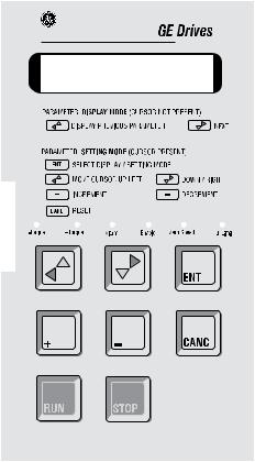
GEI-100332Ga
2.3 Drive Keypad Description
Keypad
The keypad is made of a LCD display with two 16digit lines and of 8 function buttons.
It is used:
-to command the drive when this system has been selected
-to display the speed, the voltage ..... during the operating time
-to set parameters
LED module KC
In the standard delivery the convert is supplied with the led module mounted on the front cover. It contains six leds for an easy monitoring of the converter status.
The KC module can be manually removed and replaced with the Keypad , which is connected to the regulation board through the dedicated connector.
On the Keypad, which is supplied as optional, the same leds at the KC module are mounted.
2 |
6 |
——— DESCRIPTION, COMPONENT IDENTIFICATION AND SPECIFICATIONS ——— |
|
|
DV-300 Adjustable Speed Drives |
|
LEDs |
|
|
|
|
|
Table 2.3.1: Keypad LEDs |
|
|
|
|
|
Designation |
Color |
Function |
|
- Torque |
yellow |
the LED is lit, when the drive operates with a negative torque |
|
(anti-clockwise rotation or clockwise braking). Only for 6KDV3...Q4. |
|||
|
|
||
+ Torque |
yellow |
the LED is lit, when the drive operates with a positive torque |
|
(clockwise rotation or anti-clockwise braking). Braking only for 6KDV3...Q4. |
|||
|
|
||
Alarm |
red |
the LED is lit, it signals the intervention and the alarm condition |
|
Enable |
green |
the LED is lit, when the converter is enabled |
|
Zero Speed |
yellow |
the LED is lit, when the motor speed is lower than the threshold set by Speed zero level |
|
I Limit |
yellow |
the LED is lit, when the converter operates at a current limit |
GD0020g
——— DESCRIPTION, COMPONENT IDENTIFICATION AND SPECIFICATIONS ——— |
7 |
2 |
GEI-100332Ga
2.4 Specifications
2.4.1 Standards
General: |
EN 61800-1, EN 50178. |
|
Climatic conditions: |
IEC 68-2 part 2 and 3 |
(EN 60068-2-2, test Bd). |
Isolations distances: |
IEC 664, IEC 664A; |
Environment pollution degree 2. |
Interference immunity: EN 61000-4-4, Interference immunity level 4 |
||
|
EN 61000-4-2, Interference immunity level 6 kV CD / 8 kV AD. |
|
Oscillation test: |
EN 60068-2-6, test Fc. |
|
EMC compatibility: |
EN 68100-3, see information in “EMC Guidelines”. |
|
Safety: |
EN 50178. |
|
Protection degree: |
EN 60529. |
|
UL approvation: |
According to file No. E 61641 for approved drives series. |
|
2.4.2 AC Input
Table 2.4.2.1: AC input votages
DC Drive series |
Power section |
Field circuit |
Power supply regulation section |
|
(U/V/W terminals) |
(U1/V1 terminals) |
(U2/V2 terminals) |
|
230 V ±10 %*, 3Ph |
|
|
6KDV3...Q2A |
400 V ±10 %*, 3Ph |
|
|
6KDV3...Q4E |
|
|
|
|
50/60 Hz ±5 % |
230 V ±10 %*, 1Ph |
115 V ±15 % **, 1Ph |
|
230 V ±10 %*, 3Ph |
400 V ±10 %*, 1Ph |
or |
|
400 V ±10 %*, 3Ph |
460 V ±10 %, 1Ph |
230 V ±15 % **, 1Ph |
|
440 V ±10 %, 3Ph |
|
|
6KDV3...Q2B |
460 V ±10 %, 3Ph |
50/60 Hz ±5 % |
50 / 60 Hz ±5 % |
6KDV3...Q4F |
480 V ±10 %, 3Ph |
|
|
|
500 V ±10 %, 3Ph |
|
|
|
50/60 Hz ±5 % |
|
|
|
|
|
Gd030ge |
*With the indicated tolerance values the output voltage complies the DIN 40030 standard. With wider tolerances the max output voltage chenges accordingly.
**To work at 115 V with drives from 224 Amps and above a jumper between terminals SA - SB (placed on the rear size of the drive) must be inserted.
2 |
8 |
——— DESCRIPTION, COMPONENT IDENTIFICATION AND SPECIFICATIONS ——— |
DV-300 Adjustable Speed Drives
As for 6KDV3...Q2C / Q4G converters see Appendix A (GEI-100332C).
During start-up the threshold for the undervoltage message has to be set via the Undervolt thr parameter (standard: 230 V).
Note! |
According the input voltage the switch S15.7/8 on the regulation board must be set as follows: |
||||||
|
6KDV3... |
Q2A; 6KDV3 |
...Q4E |
S15.7 |
= OFF |
S15.8 |
= OFF |
|
6KDV3... |
Q2B; 6KDV3... |
Q4F |
S15.7 |
= ON |
S15.8 |
= OFF |
|
6KDV3... |
Q2C; 6KDV3... |
Q4G |
S15.7 |
= OFF |
S15.8 |
= ON |
Note! |
As for the operation of the DV-300 converters AC input reactors and interference suppression |
||||||
|
filters are required. See section 4.10, “Reactors/Filters”. |
|
|
||||
The converters above 560 / 770 A (American / European) and the AC input reactors have a discharge currents to ground higher than 3.5 mA. EN 50178 states that beside the ground conductor another ground connection should be laid.
Caution! Duetotheincreaseddischargecurrentinvolved,afixedgroundconnection(withoutconnectors) for the filters of the DV-300 converter is required.
Table 2.4.2.2: AC input curents
American |
Current on the |
European |
Current on the |
Current on the |
Power Supply Regulation |
||
|
|
|
|
|
|
|
|
|
AC Input |
|
AC Input |
field AC Input |
Power |
Card |
|
6KDV3017... |
17.2 A |
6KDV3020... |
17.2 A |
10 A |
|
|
|
6KDV3035... |
34.4 A |
6KDV3040... |
34.4 A |
10 A |
|
|
|
6KDV3056... |
60.2 A |
6KDV3070... |
60.2 A |
10 A |
70W |
SW1-31 |
|
6KDV3188... |
75.6 A |
6KDV3110... |
94.6 A |
14 A |
|
|
|
6KDV3112... |
96.2 A |
6KDV3140... |
120.4 A |
14 A |
|
|
|
6KDV3148... |
127.2 A |
6KDV3185... |
159.1 A |
20 A |
|
|
|
6KDV3224... |
192.5 A |
6KDV3280... |
240.8 A |
20 A |
|
|
|
6KDV3280... |
240.6 A |
6KDV3350... |
301 A |
20 A |
110W |
SW2-32 |
|
6KDV3336 |
288.7 A |
6KDV3420 |
361.2 A |
20 A |
|||
|
|
||||||
6KDV3400... |
343.7 A |
6KDV3500... |
430 A |
20 A |
|
|
|
6KDV3450... |
386.7 A |
6KDV3650... |
559 A |
20 A |
|
|
|
6KDV3560... |
481.2 A |
6KDV3770... |
662.2 A |
25 A |
|
|
|
6KDV3800... |
687.4 A |
6KDV310H... |
860 A |
25 A |
110W |
SW3-32 |
|
6KDV3850... |
730.4 A |
|
|
25 A |
|
|
|
GD0040g
*Current reduction for higher temperatures, see “Permissible ambient conditions”.
**The overload size and duration depend on the overload cycle, see section 6.14.5, “Overload control”.
As for sizes above 850 / 1050 A (American / European) see Appendix A (GEI-100332C).
——— DESCRIPTION, COMPONENT IDENTIFICATION AND SPECIFICATIONS ——— |
9 |
2 |
GEI-100332Ga
2.4.3 Output
Note! It is not possible to connect an external voltage to the converter output terminals! It is not even possible to disconnect the motor from the device output while the drive is active.
In normal cases no leveling choke is necessary. It must be taken into account, anyway, that some motor producers prescribe such a choke according to the type of the motor used. In this case it must inserted on the motor cable.
The stated currents refer to the continuative operation with an ambient temperatrue of 104°F (40° C).
Output current
Armature circuit
Table 2.4.3.1: Output currents
|
American |
|
|
European |
|
Field converter |
|
Armature current |
|
Armature current |
(Term. C1 / D1) |
||
|
(Terminals C / D) |
|
(Terminals C / D) |
|
||
|
Continuous curr. |
*Max. current |
|
Continuous curr. |
*Max. current |
Continuous curr. |
|
with Ambient |
(with overload) |
|
with Ambient |
(with overload) |
with Ambient |
|
temp @ 104°F |
** |
|
temp @ 104°F |
** |
temp @ 104°F |
6KDV3017... |
17 A |
34 A |
6KDV3020... |
20 A |
40 A |
10 A |
6KDV3035... |
35 A |
70 A |
6KDV3040... |
40 A |
80 A |
10 A |
6KDV3056... |
56 A |
112 A |
6KDV3070... |
70 A |
140 A |
10 A |
6KDV3088... |
88 A |
172 A |
6KDV3110... |
110 A |
220 A |
14 A |
6KDV3112... |
112 A |
224 A |
6KDV3140... |
140 A |
280 A |
14 A |
6KDV3148... |
148 A |
296 A |
6KDV3185... |
185 A |
370 A |
14 A |
6KDV3224... |
224 A |
448 A |
6KDV3280... |
280 A |
560 A |
20 A |
6KDV3280... |
280 A |
560 A |
6KDV3350... |
350 A |
700 A |
20 A |
6KDV3336... |
336 A |
672 A |
6KDV3420... |
420 A |
840 A |
20 A |
6KDV3400... |
400 A |
800 A |
6KDV3500... |
500 A |
1000 A |
20 A |
6KDV3450... |
450 A |
900 A |
6KDV3650... |
650 A |
1300 A |
20 A |
6KDV3560... |
560 A |
1120 A |
6KDV3770... |
770 A |
1540 A |
25 A |
6KDV3800... |
800 A |
1600 A |
6KDV310HQ2... |
1000 A |
2000 A |
25 A |
6KDV3850... |
850 A |
1700A |
6KDV310HQ4... |
1050 A |
2100 A |
25 A |
|
|
|
|
|
|
GD0050g |
*Current reduction for higher temperatures, see section 3.1, “Permissible ambient conditions”.
**The overload size and duration depend on the overload cycle, see section 6.14.5, “Overload control”
As for sizes above 850 / 1050 A (American / European) see Appendix A (GEI-100332C).
Note! The field motor current can sometimes be very small compared with rated field current of the converter. In order to provide regulation during Voltage control of the motor, follow the described instructions to change the Flux current max of the converter. In this case the Nom field scale parameter must be set with the new rated field current value.
2 |
10 |
——— DESCRIPTION, COMPONENT IDENTIFICATION AND SPECIFICATIONS ——— |
Loading...