


Digital Energy GT Series UPS 5
Table of contents
 Loading...
GE Digital Energy
Power Quality
User manual
Digital Energy™ Uninterruptible Power Supply
GT Series UPS
5/6/8/10 kVA
GT5000 RT / GT6000 RT GT8000 RT / GT10000 RT
GE Digital Energy™
General Electric Company
CH – 6595 Riazzino (Locarno)
Switzerland
T +41 (0)91 / 850 51 51
F +41 (0)91 / 850 52 52
www.GEDigitalEnergy.com
imagination at work

User manual
GT Series - Uninterruptible Power Supply
5/6/8/10 kVA
We thank you for selecting a General Electric Digital Energy™ GT Series
Uninterruptible Power Supply.
Please read these instructions carefully before installation and start-up of the
GT Series UPS. Keep this manual in a safe place for future reference.
Model:
GT Series / Series 1
Date of issue: 09.01.2008
File name: OPM_GTS_XUL_5K0_10K_XUS_V010
Revision: 1.0
Identification No.:
Up-dating
Revision Concern Date
© General Electric Digital Energy™. All rights reserved; reproduction without permission prohibited. The content of this manual
may be subject to change without prior notice; no liability can be accepted for any error or omission. The illustrations and plans
describing the equipment are intended as general reference only and are not necessarily complete in every detail.
modifications reserved 2 User manual GT Series 5/6/8/10 kVA UPS 1.0 (US)

Contents
1 IMPORTANT SAFETY INSTRUCTIONS ....................................................................................................... 4
1.1 Save these instructions.....................................................................................................................................................................4
1.2 Safety warnings and symbols .......................................................................................................................................................4
1.3 General......................................................................................................................................................................................................5
1.4 Transport / storage.............................................................................................................................................................................5
1.5 Maintenance and servicing.............................................................................................................................................................6
1.6 FCC Compliance Statement............................................................................................................................................................6
2 INTRODUCTION........................................................................................................................................... 7
2.1 Introduction ............................................................................................................................................................................................7
2.2 Intended use...........................................................................................................................................................................................7
2.3 Warranty ..................................................................................................................................................................................................7
2.4 diagram.....................................................................................................................................................................................................7
3 INSTALLATION............................................................................................................................................. 8
3.1 Package contents ................................................................................................................................................................................8
3.2 Installation rules ...................................................................................................................................................................................8
3.3 Installation procedure .......................................................................................................................................................................9
3.3.1 Tower installation – preparations (all models)........................................................................................................................9
3.3.2 Rack mount installation – preparations (all models)........................................................................................................10
3.3.3 Connecting internal battery pack (for 5/6 kVA models)..................................................................................................11
3.3.4 Connecting internal batteries (for 8/10 kVA models only) .............................................................................................12
3.3.5 Connecting additional external batteries (5/6 kVA models)..........................................................................................13
3.3.6 Connecting additional external batteries (8/10 kVA models)....................................................................................... 14
3.3.7 Connecting interface devices............................................................................................................................... .......................16
3.3.8 Rear panel............................................................................................................................................................................................. 17
3.3.9 Standard installation procedure ................................................................................................................................................18
3.4 Parallel Operation (only for 8/10 kVA) .....................................................................................................................................20
3.4.1 Installation of a parallel system.................................................................................................................................................20
3.4.2 Installing the parallel connection ..............................................................................................................................................21
4 OPERATION................................................................................................................................................ 22
4.1
Operating panel..................................................................................................................................................... 22
4.2 Start-up..................................................................................................................................................................... 23
4.2.1 Start-up of a 5/6 kVA .......................................................................................................................................................................23
4.2.2 Start-up of a 8/10 kVA.....................................................................................................................................................................24
4.2.3 Start-up of a parallel system (8/10 kVA models)................................................................................................................24
4.3 Use: normal operation........................................................................................................................................ 25
4.3.1 Normal operation conditions.......................................................................................................................................................25
4.3.2 Switching off............................................................................................................................... .........................................................25
4.3.3 Maintenance Bypass.......................................................................................................................................................................26
4.4 Use: status and alarm indications................................................................................................................. 27
4.4.1 On bypass .............................................................................................................................................................................................28
4.4.2 On battery.............................................................................................................................................................................................28
4.4.3 Battery low (end of runtime).........................................................................................................................................................28
4.4.4 Bypass out of limits...........................................................................................................................................................................28
4.4.5 Overload ................................................................................................................................................................................................28
4.4.6 Replace battery............................................................................................................................... ...................................................29
4.4.7 Alarm priority....................................................................................................................................................................................... 29
4.4.8 Fault mode............................................................................................................................................................................................ 29
4.4.9 Stand-by ................................................................................................................................................................................................29
4.4.10 Remote Emergency Power Off (REPO) .....................................................................................................................................30
4.4.11 No load shutdown.............................................................................................................................................................................30
4.4.12 Auto Restart .........................................................................................................................................................................................30
4.5 Battery management ......................................................................................................................................... 31
5 COMMUNICATION .................................................................................................................................... 32
5.1 DB9 Communication port .............................................................................................................................................................32
5.2 SNMP interface card (option).......................................................................................................................................................32
6 OPTIONS..................................................................................................................................................... 33
6.1 Optional Power Distribution UNIT .............................................................................................................................................33
6.1.1 5/6 kVA PDUs....................................................................................................................................................................................... 34
6.1.2 8/10 kVA PDUs....................................................................................................................................................................................34
6.2 Extended Runtime ............................................................................................................................................................................34
7 MAINTENANCE .......................................................................................................................................... 35
7.1 Safety ......................................................................................................................................................................................................35
7.2 General...................................................................................................................................................................................................35
7.3 Recycling the UPS at the end of service life.........................................................................................................................35
7.4 Batteries................................................................................................................................................................................................. 36
7.4.1 Internal battery replacement (for 5/6 kVA models)........................................................................................................... 37
7.4.2 Internal battery replacement (for 8/10 kVA models)........................................................................................................38
7.5 Power unit maintenance ............................................................................................................................................................... 39
7.5.1 Power unit replacement (for 5/6 kVA models).....................................................................................................................39
7.5.2 Power unit replacement (for 8/10 kVA models).................................................................................................................. 39
8 TROUBLESHOOTING................................................................................................................................. 40
9 SPECIFICATIONS ....................................................................................................................................... 41
modifications reserved 3 User manual GT Series 5/6/8/10 kVA UPS 1.0 (US)
1 IMPORTANT SAFETY INSTRUCTIONS
1.1 SAVE THESE INSTRUCTIONS
This manual contains important instructions that should be followed during installation and maintenance of the UPS.
It also gives all necessary information about the correct use of the UPS. Before attempting to install and start up the
UPS, carefully read this manual. Keep this manual next to the unit for future references.
Full understanding of and compliance with the safety instructions and warnings contained in this
manual are the
ONLY CONDITIONS
to avoid any dangerous situation during installation, operation and maintenance work, and to
preserve the maximum reliability of the UPS system.
GE refuses any responsibility in case of non-observance, unauthorized alterations or improper use of
the delivered UPS.
While every care has been taken to ensure the completeness and accuracy of this manual, GE accepts
no responsibility or liability for any loss or damage resulting from the use of the information contained
in this document.
This document shall not be copied nor reproduced without the permission of GE.
Due to technical improvements, some of the information contained in this manual may be changed
without notice.
The instructions in this manual are for UPS models GT5000 RT, GT6000 RT, GT8000 RT and GT10000 RT. Check your
model number by looking at the top cover of your UPS. Any difference in instructions is clearly indicated in the text
(for instance ‘GT10000 RT’).
1.2 SAFETY WARNINGS AND SYMBOLS
Safety warnings
The text of this manual contains warnings to avoid risk to persons and to avoid damages to the UPS system and the
supplied critical loads. Do not proceed beyond these warnings if you do not fully understand and/or are not able to
meet the mentioned conditions. The non-observance of the warnings reminding hazardous situations could result in
human injury and equipment damage.
Please pay attention to the meaning of the following warnings and symbols.
WARNING!
Refers to procedures or operations which, when not correctly performed, could
cause personal injury or serious damage to the system.
NOTE
Warns the user about important operations or procedures described in this
manual.
Safety Symbols
CAUTION
The product may be in danger: when procedures or operations are not correctly
performed, damage to the product may be the result.
DANGER OF ELECTRICALLY LIVE PARTS
Related to all situations with potentially hazardous voltage.
modifications reserved 4 User manual GT Series 5/6/8/10 kVA UPS 1.0 (US)
1.3 GENERAL
DANGER! RISK OF ELECTRIC SHOCK.
The UPS has an internal battery supply with a nominal voltage of 144Vdc / 288Vdc.
Some of the parts of the UPS are necessarily under a hazardous voltage. Do not
open the unit; there are no user serviceable parts inside.
The appliance outlets and output terminals may be electrically live, even when the
UPS is disconnected from the mains.
CAUTION
There may be damage to the equipment if procedures and practices are not strictly
observed and followed.
1.4 TRANSPORT / STORAGE
NOTE
Check for sufficient floor and elevator loading capacity. Move the UPS and the
battery pack in its original package to the final destination room. Do not stack
other package on top.
WARNING!
Pay attention to the HEAVY WEIGHT of the UPS when downloading the UPS from
the pallet! Never try to lift the unit by yourself!
• No liability can be accepted for any transport damage when the equipment is shipped in non-original
packaging.
• Store the UPS in a dry location with the batteries in a fully charged state. Storage temperature must be
within -20 +45 °C (-4°F and 113°F). If the unit is stored for a period exceeding 3 months, optimal battery
lifetime is obtained if the storage temperature does not exceed 30°C (86°F).
• If the unit is stored for an extended period of time, the batteries must be recharged periodically.
Connect the unit to a wall outlet and recharge the batteries for 24 hours:
- if the storage temperature is within -20 and +30°C (-4°F and 86°F): every 6 months,
- if the storage temperature is within -20 and +45°C (-4°F and 113°F): every 3 month.
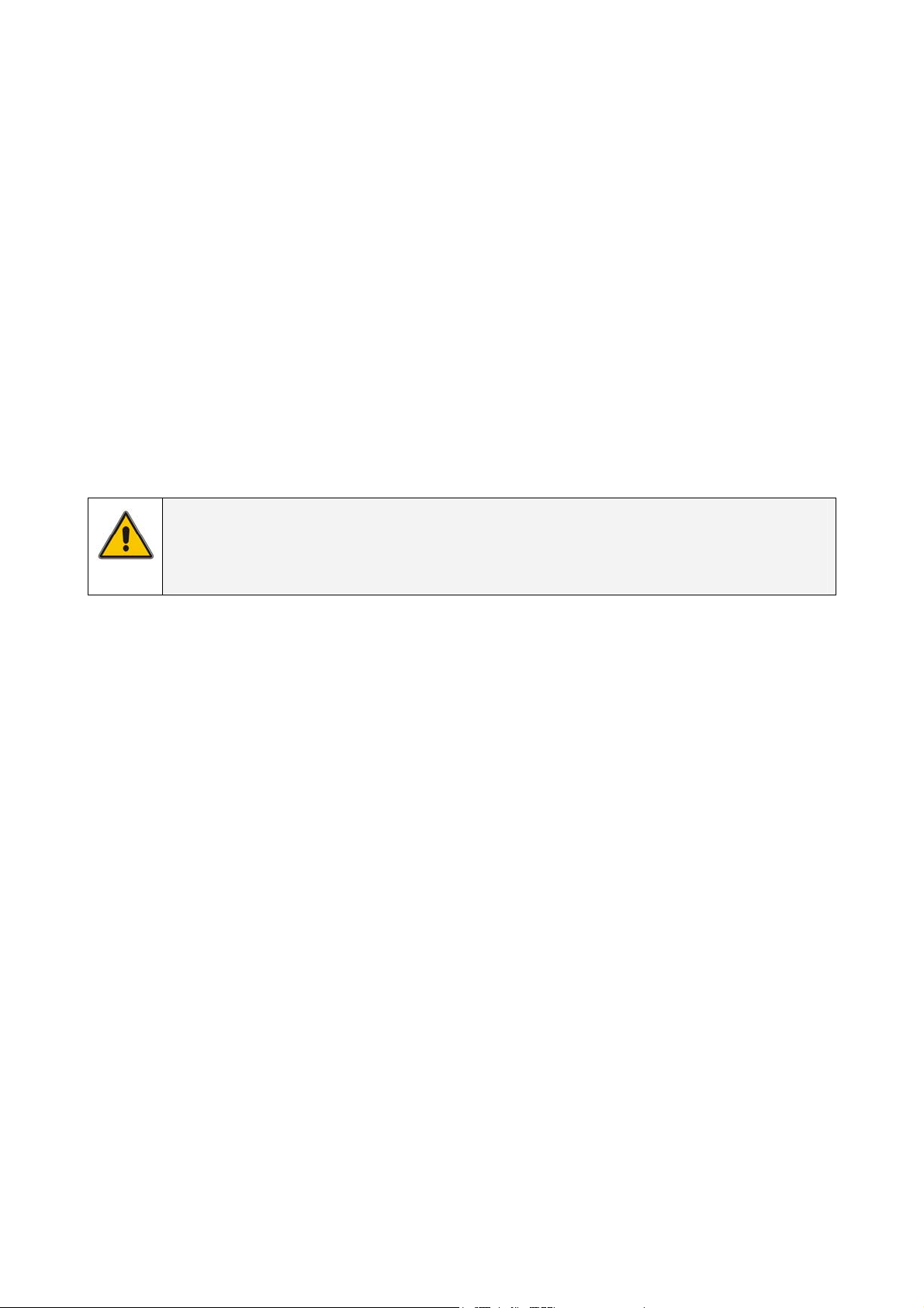
CAUTION
In case of storage, pay attention to:
modifications reserved 5 User manual GT Series 5/6/8/10 kVA UPS 1.0 (US)
1.5 MAINTENANCE AND SERVICING
• A battery can present a risk of electrical shock and high short circuit current
• Never dispose of batteries in a fire: they may explode
• Do not open or mutilate batteries: their contents may be extremely toxic. If exposed to electrolyte,
wash immediately with plenty of water
• The batteries must be disconnected during maintenance or service work.
• When replacing the batteries, use only the same type and size battery.
• The following precautions should be observed when working on batteries:
- Remove watches, rings or other metal objects.
- Use tools with insulated handles.
- Wear rubber gloves and boots.
- Do not lay tools or metal parts on top of batteries.
- Disconnect charging source prior to connecting or disconnecting battery terminals.
- Determine if the battery is inadvertently grounded. If inadvertently grounded, remove source of
ground. Contact with any part of a grounded battery can result in electrical shock. The likelihood of
such shock will be reduced if such grounds are removed during installation and maintenance.
• Avoid charging in a sealed container.
NOTE
Do not attempt to service the UPS unless you have had proper training. Refer all
maintenance and servicing, except replacement of the batteries and plug-in cards,
to properly qualified, skilled and competent service personnel.
Qualified, skilled personnel are persons who (because of their training, experience, and position as well as
their knowledge of appropriate standards, regulations, health and safety requirements and working
conditions) are authorized to be responsible for the safety of the equipment, at all times whilst carrying out
their normal duties and are therefore aware of, and can report, possible hazards (observe IEC 60364 and
national wiring regulations and accident prevention rules).
1.6 FCC COMPLIANCE STATEMENT
Note: This equipment has been tested and found to comply with the limits for a Class A digital device,
pursuant to Part 15 of the FCC Rules. These limits are designed to provide reasonable protection against
harmful interference when the equipment is operated in a commercial environment. This equipment
generates, uses and can radiate radio frequency energy and, if not installed and used in accordance with
the instruction manual, may cause harmful interference to radio communications. Operation of this
equipment in a residential area is likely to cause harmful interference in which case the user will be
required to correct the interference at their own expense.
Modifications not expressly approved by the manufacturer could void the user’s authority to operate the
equipment under FCC rules.
modifications reserved 6 User manual GT Series 5/6/8/10 kVA UPS 1.0 (US)
2 INTRODUCTION
2.1 INTRODUCTION
The GE Digital Energy™ GT Series UPS, a truly on-line uninterruptible power supply, protects your
equipment from all forms of power interference, including complete power failures.
2.2 INTENDED USE
Uninterruptible Power Supplies (UPS) are designed to protect sensitive electronic equipment such as
computers and telecommunications equipment from all forms of power interference.
CAUTION!
DO NOT plug household appliances such as electric heaters, toasters or vacuum
cleaners into the UPS. The UPS output is intended to be used only for electronic
loads such as computers and telecommunications equipment.
The technical data as well as information concerning connecting requirements can be found on the rating
label and in this document and shall be strictly observed.
2.3 WARRANTY
GE Digital Energy™ warrants that the standard products will be free of defects in materials and
workmanship for a period of twenty-four (24) months after seller’s shipment date.
NOTE
This warranty does not cover failures of the product that result from incorrect
installation, misuse, alterations by persons other than authorized agents,
or abnormal operating conditions.
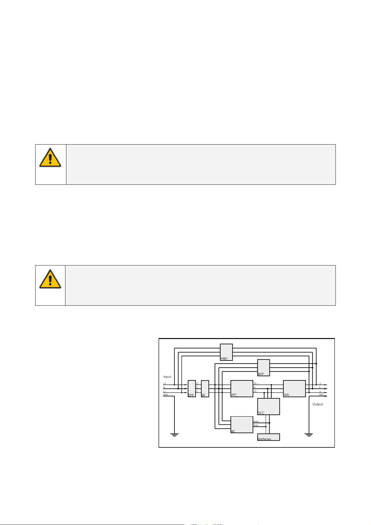
2.4 DIAGRAM
EMI: Input filter with surge
suppression, radio frequency
and electromagnetic
interference filter.
BF: Back-feed protection.
PFC: AC-DC converter with power
factor correction.
BC: Battery charger.
DCC: DC-DC converter.
INV: Inverter.
BYP: Bypass switch.
MBY: Manual bypass switch.
fig. 2.4
modifications reserved 7 User manual GT Series 5/6/8/10 kVA UPS 1.0 (US)
3 INSTALLATION
3.1 PACKAGE CONTENTS
5/6 kVA model shipping box contains:
• 2 front bezels
• 2 top bezels
• 6 support stands parts
• 2 rack mount handles
• 1 screw set – 1 display sticker
• 1 RS232 cable, 2 ferrite beads
• 1 CD ROM (Software tool)
• This Operating Manual
8/10 kVA model shipping box contains:
• 3 front bezels
• 3 top bezels
• 6 support stands parts
• 2 internal battery brackets
• 2 rack mount handles
• 1 screw set – 1 display sticker
• 1 paralleling cable
• 1 RS232 cable, 2 ferrite beads
• 1 CD ROM (Software tool)
• This Operating Manual
Inspect the UPS for damage after unpacking. If any damage is present please immediately notify the carrier and
place of purchase.
NOTE
The internal battery packs are shipped separately, see section 3.3.3 and 3.3.4
for the installation details
WARNING! In case of recognizable damage:
DO NOT connect any voltage to the unit
DO NOT put the unit into operation
3.2 INSTALLATION RULES
IMPORTANT
Before making any connection and switching on the GT Series UPS,
please check the following conditions:
• All electrical connections are to be realized by qualified skilled personnel only.
• To avoid potential health risks, electrical components should not be mechanically damaged or destroyed. Do not
touch electronic components. They may be electrostatic sensitive and are for that reason easily damaged due to
improper handling.
• Avoid locations that are excessively humid, near water, near heat sources or in direct sunlight. It is important that
the unit has adequate ventilation. Maintain air movement around and through the unit. Do not block the air vents.
• The ambient temperature should not exceed 40°C (104°F). Optimal battery lifetime is obtained if the ambient
temperature does not exceed 30°C (86°F).
• Avoid spilling liquids or dropping any foreign object into the UPS.
• The UPS should only be powered from a two phase, four wires AC source equipped with neutral and earth
connection. Your mains supply is 100 - 127 Volts (Line-N) and 60 Hz (if the mains frequency is 50Hz, the output
frequency of the UPS can be changed, see note in section 4.4.4).
• The total power demand of the connected equipment does not exceed the rated output power of the GT Series
UPS (chapter 9 contains the ratings).
• To reduce risk of fire a disconnection switch should be installed for input and output circuit, connect only to
over-current protection branch circuit rated in accordance with the National Electric Code, ANSI/NFPA 70, see
following table:
UPS model Branch protection
GT5000 RT / GT6000 RT 30A slow
GT8000 RT / GT10000 RT 60A slow
CAUTION
To reduce risk of fire, connect the UPS only to a circuit provided with fuse values
according to the above.
modifications reserved 8 User manual GT Series 5/6/8/10 kVA UPS 1.0 (US)
3.3 INSTALLATION PROCEDURE
The UPS can be used in a stand alone tower format using the two supporting stands (section 3.3.1), or
can be mounted in a 19 inch rack using the mounting brackets (section 3.3.2). Proceed with the
corresponding section, and then connect internal batteries (section 3.3.3 fro 5/6 kVA models and section
3.3.4 for 8/10 kVA models). All required items are included in the delivery, except rails – available as rail
kit option.
NOTE
The UPS output sockets are live as soon as the UPS is connected to the main
power supply, even if the UPS has not been switched on via the front panel.
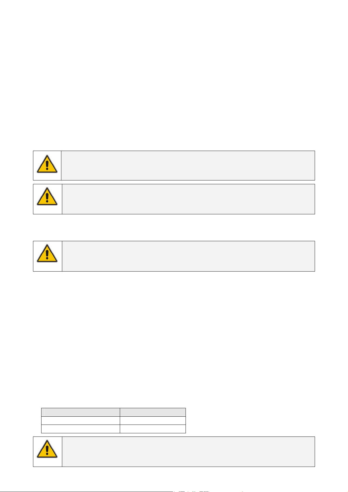
3.3.1 Tower installation – preparations (all models)
fig. 3.3.1.a
fig. 3.3.1.b
1. On 5/6 kVA models align terminals on
the backside of the PDU with UPS ones
and slide PDU in the UPS (fig. 3.3.1.a).
2. Assemble the plastic support stand
and place them in the desired position
(2, fig. 3.3.1.b / 3.3.1.c).
3. Place the cabinet upright in to the
plastic support stand and mount
top covers (3, fig. 3.3.1.b / 3.3.1.c).
4. Attach the display sticker (4, fig. 3.3.1.b /
3.3.1.c).
The GT Series UPS is now ready for further
connection: proceed with internal battery
connection.
fig. 3.3.1.c
5/6 kVA
5/6 kVA
8/10 kVA
modifications reserved 9 User manual GT Series 5/6/8/10 kVA UPS 1.0 (US)
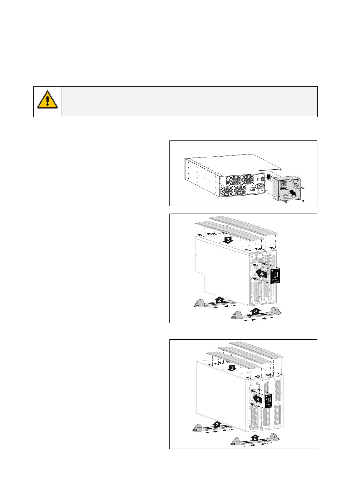
3.3.2 Rack mount installation – preparations (all models)
1. On 5/6 kVA models align
terminals on the backside of the
PDU with UPS ones and slide PDU
in the UPS (fig. 3.3.1.a).
2. Install the rack mount handles
that came with the unit using the
provided screws (2, fig.3.3.2.b /
3.3.2.c).
3. Install the UPS into a 19’ rack.
The UPS cabinet must be
supported by an (optional) rack
mount kit, do not mount it by
using the mounting brackets
only.
fig. 3.3.2.a
fig. 3.3.2.b
fig. 3.3.2.c
5/6 kVA
5/6 kVA
8/10 kVA
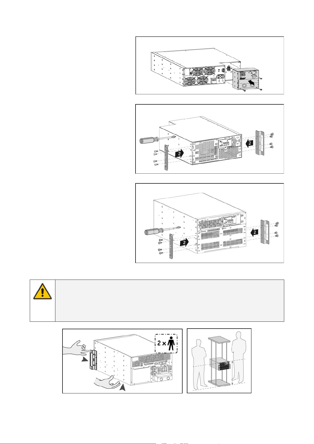
NOTE
Please consider the weight of the UPS (see section 9) prior to installation to ensure
the rack and floor are capable of supporting the weight. For rack installation we
recommend that the UPS is placed in the lower section of the rack. Fit the unit and
the battery into the rack cabinet with the help of a second person.
fig. 3.3.2.d
The GT Series UPS is now ready for further connections. Please proceed internal battery connection.
modifications reserved 10 User manual GT Series 5/6/8/10 kVA UPS 1.0 (US)
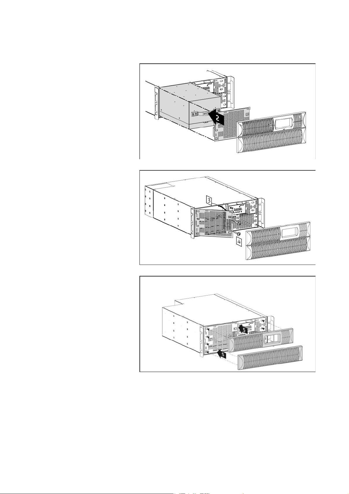
3.3.3 Connecting internal battery pack (for 5/6 kVA models)
The internal battery pack is shipped separately from the UPS cabinet. It has to be mounted inside the
unit after UPS installation. Please proceed with the following steps:
1. Unpack the battery pack from
its carton box.
2. Place the battery pack in front
of the battery compartment,
aligning the rear connector to
the front panel (2, fig. 3.3.3.a).
3. Slide the battery pack into the
battery compartment until the
rear connector is plugged with
the UPS internal DC socket.
4. Fix the battery cover by
tightening screws
(4, fig. 3.3.3.b).
5. Mount the front panels by
pushing the plastic part into
the appropriate holes
(5, fig. 3.3.3.c).
6. Proceed with the UPS
preparation.
fig. 3.3.3.a
fig. 3.3.3.b
fig. 3.3.3.c
5/6 kVA
5/6 kVA
5/6 kVA
modifications reserved 11 User manual GT Series 5/6/8/10 kVA UPS 1.0 (US)
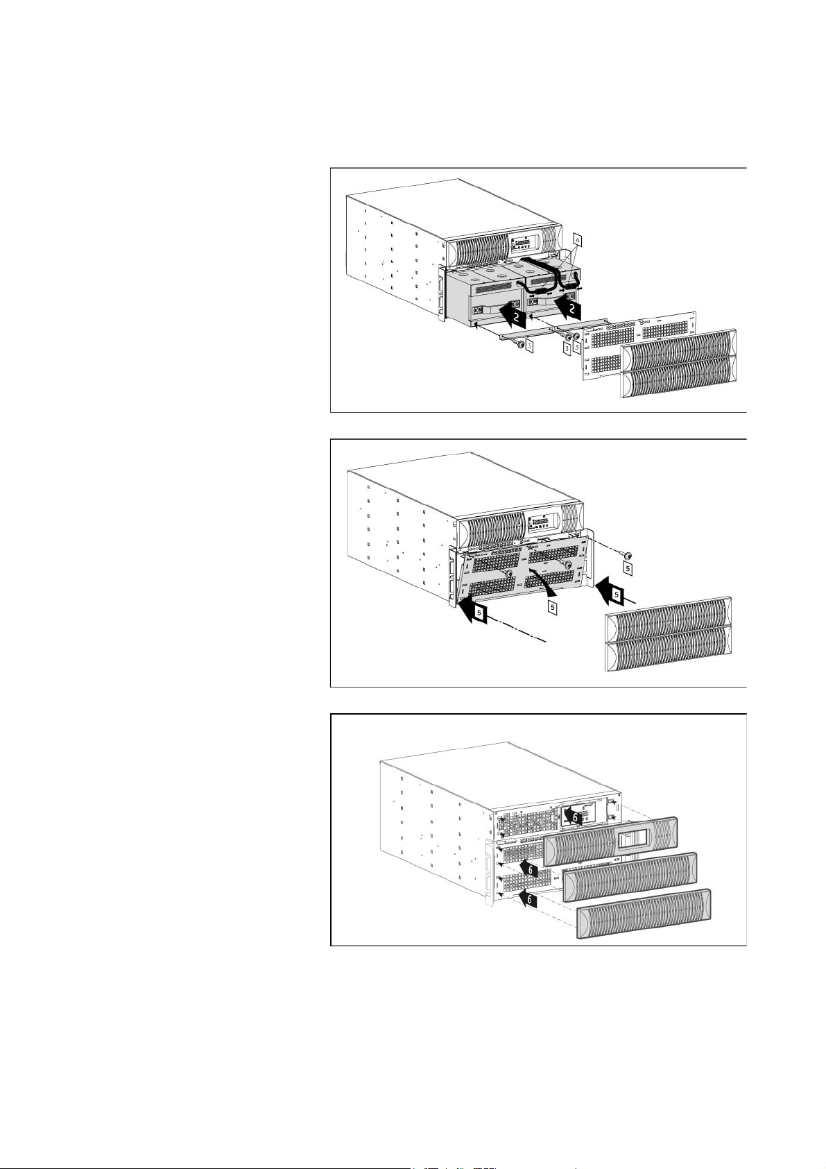
3.3.4 Connecting internal batteries (for 8/10 kVA models only)
The internal battery packs are shipped separately from the UPS cabinet. They have to be mounted
inside the unit after the UPS installation. Please proceed with the following steps:
1. Unpack the 2 battery packs
from their carton box.
2. Place the battery packs side by
side in the battery
compartment (2, fig. 3.3.4.a).
3. Fix the 2 battery brackets with
the screw set to hold battery
packs into the cabinet
(3, fig.3.3.4.a).
4. Connect the UPS DC
connectors of each battery
pack (4, fig.3.3.4.a).
5. Fix the battery grille in front of
the battery compartment with
3 screws (5, fig.3.3.4.b).
6. Mount the front panels by
pushing the plastic part into
the appropriate position
(6, fig. 3.3.4.c).
7. Proceed with the UPS
preparation.
fig. 3.3.4.a
fig. 3.3.4.b
fig. 3.3.4.c
8/10 kVA
8/10 kVA
8/10 kVA
modifications reserved 12 User manual GT Series 5/6/8/10 kVA UPS 1.0 (US)
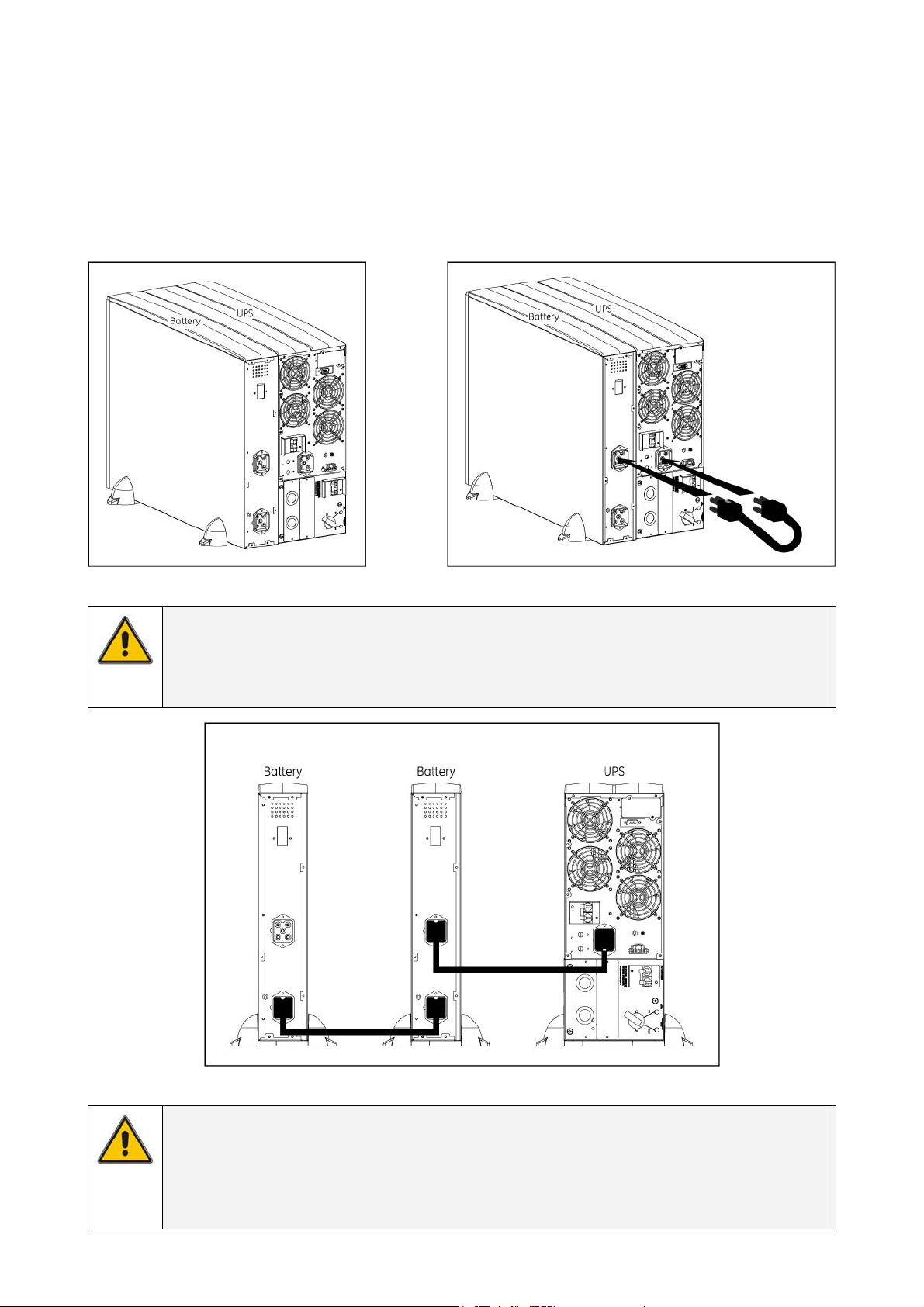
3.3.5 Connecting additional external batteries (5/6 kVA models)
The additional external battery pack connects to the UPS in the same way whether the UPS is being
used in tower or rack mount format. When used in tower format, the UPS and additional battery packs
can be mounted together in one set of mounting support stands (fig.3.3.5.a). Additional support stands
are shipped with battery cabinet.
Connect the cable provided with the battery between UPS and battery pack – plug it into the UPS
battery socket and the nearest battery connection socket on the battery pack (fig.3.3.5.b). At first start
up the value of the total battery capacity has to be set with the UPS Monitoring software.
fig. 3.3.5.a fig. 3.3.5.b
5/6 kVA 5/6 kVA
NOTE
If further battery packs are used, they connect via the previous battery pack. Thus,
the cable provided is attached via the nearest socket connection on the existing
battery cabinet (fig. 3.3.5.c).
fig. 3.3.5.c
5/6 kVA
NOTE
When the UPS is connected to the mains, and the battery pack is connected to
the UPS, the batteries start charging. For best results, allow the UPS to recharge
the batteries during a period of approx. 8 hours. It is acceptable to use the UPS
without first charging the battery, but the runtime may be reduced.
modifications reserved 13 User manual GT Series 5/6/8/10 kVA UPS 1.0 (US)
Loading...