


GE Oil & Gas
Mooney* Flowgrid* Regulator
Installation, Operation and Maintenance Manual
Scope
This manual provides installation, operation, and maintenance instructions for the Mooney Flowgrid regulator. Instructions for the Mooney Series 20 Pilot will be found in a separate manual.
Table of Contents
Product Description ............................................................................ |
1 |
Piping Details .......................................................................................... |
7 |
Regulator Markings............................................................................. |
3 |
Start-up and Operation.................................................................. |
11 |
Nameplate Information .................................................................... |
3 |
Maintenance ....................................................................................... |
13 |
Principles of Operation ...................................................................... |
4 |
Troubleshooting................................................................................. |
15 |
Hydrostatic Testing ............................................................................. |
5 |
Warranty................................................................................................ |
16 |
Installation ............................................................................................... |
6 |
Product Support................................................................................. |
16 |
Product Description
The Mooney Flowgrid regulator is an easy to maintain regulator designed to be used primarily with a self contained pilot system. The Flowgrid regulator has several unique features that add to its versatility such as:
■In line maintenance
■Replaceable trim
■Reversible trim parts
■Non stretching fabric reinforced diaphragm for stability and fast response at all temperatures
■Positive spring shutoff
■Two-stage pressure drop to minimize noise and provide cavitation protection
GE Oil & Gas has secured global PED EN 334 certification for its Mooney Flowgrid regulators demonstrating our commitment to quality and safety. The certification was awarded by DVGW (the German Technical and Scientific Association for Gas and Water), one of the world’s most recognized industry certification bodies and the largest gas and water industry certification agency in Europe. GE Oil & Gas has also secured the following verifications; ISO 9901, ISO 14001, CRN along with others ensuring the safety and quality of the Mooney regulator.
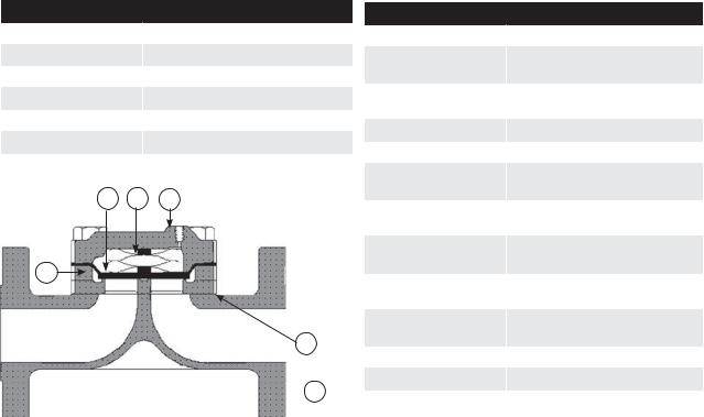
Table 1
Materials of Construction
Body & Spring Case |
|
ASTM A 216 WCB Carbon Steel |
Spacer |
|
ASTM A 216 WCB Carbon Steel |
Throttle Plate |
|
17-4PH Stainless Steel |
Diaphragm |
|
Nitrile/Nylon (Optional - Viton/Nylon) |
O-Ring & Seals |
|
Nitrile (Optional - Viton) |
Bolting |
|
ASTM 193 GR B-7 or Equal |
Spring |
|
301 Stainless Steel |
4 |
5 |
6 |
3
2
 1
1
Figure 1 - Flowgrid Parts
All Mooney Flowgrid regulators have six main parts (excluding bolting and O-rings); the body, throttle plate, spacer, diaphragm, main spring, and spring case. Although parts vary in size and design, all regulators share the same principle of operation.
The body (1) is constructed with a single port (sizes less than 10”) and a dual port (sizes greater than 10”). The dual port design can provide redundant control if equipped with dual pilots or be used with a single pilot for maximum capacity.
The throttle plate (2) supports the diaphragm and provides a machined surface that the diaphragm seals against for bubble tight shutoff. Restricted capacity plates of 35%, 50%, and 75% are available.
The spacer (3) creates a space between the throttle plate and the diaphragm which forms a flow path inside the regulator.
Table 2
Specifications
Sizes |
1” - 12” (DN 25 - DN300) |
Body Style |
Single Port |
|
10 inch and 12 inch Dual Ports |
End Connections |
Screwed, Socket Weld |
|
Flanged, Flangeless & Buttweld |
Temperature |
-20°F to 150°F (-29°C to 66°C) |
Min/Max Temperature |
-40°F to 175° F (-40°C to 79° C) |
Maximum Operating |
800 psi (55.16 bar) |
Differential |
|
Maximum Emergency |
1000 psi (68.9 bar) |
Differential |
(unless limited by body rating) |
Minimum Differential |
Refer to individual product |
|
specification sheets |
Cracking Differential |
Refer to individual product |
|
specification sheets |
Maximum Inlet Pressure |
1480 psig (102.1 bar) |
|
(limited by flange or pilot rating) |
Outlet Pressure Range |
Limited by pilot |
Flow Direction |
Bi-Directional1 |
Body Taps |
1/4” - 18 NPT |
1 Reverse flow by changing pilot connections and reversing spring case.
The fabric-reinforced diaphragm (4) is the main working part of the Flowgrid regulator. The diaphragm functions as both an actuator and the regulator throttling element.
It is designed to provide stability, rangeability, and fast response without stretching. It will not “take a set” and is thick for durability and wear resistance.
The main spring (5) provides high frequency response, proportional action for stability and a consistent minimum differential regardless of temperature.
It also provides a positive closing force, which is important in monitor regulation applications.
The spring case (6) is shaped to retain the main spring. It provides a low volume cavity where loading pressure from the pilot system is placed on top of the diaphragm to control flow through the regulator.
2
Regulator Markings
Front View |
Back View |
Top View |
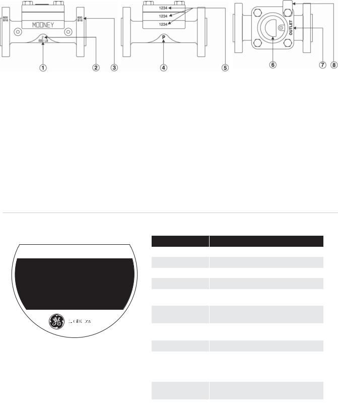
Figure 2 - Regulator Markings
1. American National Standards Institute (ANSI) pressure class rating of the regulator.
2.Line size of body.
3.ANSI pressure class rating of the flange.
4.Indication that the regulator has been hydrostatically tested according to code requirements.
5.The serial number is stamped on the spring case, spacer1, and body.
6.The Nameplate location.
7.The flow direction is marked on the spring case (“INLET” or “OUTLET”). Proper alignment assures that the diaphragm guide on the Spring Case is aligned toward outlet side of the regulator.
8.The % Capacity tag indicates the capacity of the throttle plate (100%, 75%, 50%, & 35%) in the regulator. 1NOTE: On all 1” regulators and 2” standard regulators the throttle plate itself is stamped.
Nameplate Information
Mooney™ Flowgrid™ Regulator |
U.S. Pat. Nol 4,659,062 |
Salt Lake City, UT USA |
Canadian Pat. No. 1,250,207 |
|
|
|
|
|
|
S/N |
|
|
|
|
|
|
|
FG- |
|
|
|
||
|
|
|
|
|
|
Size/Ends |
|
|
|
|
|
|
|
|
|
|
|||
|
|
|
|
|
|
|
|
|
|
|
|
|
|
|
|||||
|
|
|
|
|
|
|
|
|
|
|
|
||||||||
ANSI Cl |
|
|
|
|
|
|
Max |
|
|
|
|
bar |
|
|
|
|
|||
|
|
|
|
|
|
|
|
|
|
|
|
|
|
||||||
|
|
|
|
|
|
Inlet psi |
|
|
|
|
|
||||||||
|
YR |
|
|
|
|
Diff |
|
|
|
|
bar |
|
|
|
|
|
|
||
|
|
|
|
Min/Maxpsi |
|
|
|
|
|
|
|
|
|||||||
|
|
|
|
|
|
|
|
|
|
|
|
|
|
|
|
|
|||
|
Max |
|
|
|
|
|
Bolt Torq |
|
|
|
|
|
|
|
|
||||
|
|
|
|
|
|
|
|
|
|
|
|
|
|
||||||
|
Temp°F/°C |
|
|
|
|
|
Ft-lbs/Nm |
|
|
|
|
|
|
|
|
||||
Figure 3 - Flowgrid Nameplate
Table 3 |
|
|
Item |
Definition |
|
Flowgrid |
Registered name of regulator |
|
BLANK |
CE Marking |
|
SN |
Serial number assigned to regulator |
|
FG |
Flowgrid Model description |
|
SIZE/END CONN |
Line size of bogy an type of end |
|
|
connection |
|
ANSI CL |
American National Standards Institute |
|
|
pressure class |
|
MAX INLET |
Maximum inlet pressure (psig)/(bar) |
|
PRESSURE |
|
|
YR |
Year manufactured |
|
|
Minimum differential required to fully |
|
DIFF/MIN/MAX |
open regulator |
|
Maximum allowable operating pressure |
||
|
||
|
differential (psig)/(bar) |
|
MAX F |
Maximum Operating Temperature in |
|
TEMPERATURE |
degrees Fahrenheit |
|
BOLT TORQ |
Recommended bolt torque for spring |
|
FT-LBS/n-m |
case in foot pounds |
3

Principles of Operation |
|
|
|
|
Pilot Supply |
Pilot Sense |
|
Pilot Supply |
Pilot Sense |
|
Connection |
|
|
Connection |
Restrictor |
|
|
Restrictor |
|
Pilot Loading |
|
|
Pilot Loading |
|
Connection |
|
|
Connection |
|
|
Pilot Outlet |
|
|
Pilot Outlet |
|
Connection |
|
|
Connection |
Inlet |
Outlet |
INLET |
|
Outlet |
Inlet |
|
Figure 4 - Pressure Reducing Configuration Fully Closed
At no flow, when the outlet pressure is greater than the set point of the pilot regulator, the pilot is closed and full inlet pressure loads the spring case through the pilot loading connection. In this condition the diaphragm is closed tightly against the throttle plate. The pressure differential across the outlet half of the diaphragm adds to the spring force in closing the Flowgrid regulator (Refer to Figure 4).
As demand for flow occurs in the downstream system the outlet pressure drops, causing the pilot regulator to open and start bleeding pressure out of the spring case faster than it can enter through the restrictor. Reducing the pressure above the diaphragm allows the inlet pressure to progressively lift the diaphragm off the throttle plate, opening the regulator and satisfying the demand for flow in the downstream system. (Refer to Figure 5).
Figure 5 - Pressure Reducing Configuration Partially Open
When demand for flow ceases or is reduced, the downstream pressure increases causing the pilot regulator to close. Inlet pressure continues to pass through the restrictor until the control pressure equals the inlet pressure. The spring force, plus the pressure differential across the outlet half of the diaphragm closes the diaphragm against the throttle plate, shutting off the flow (Refer to Figure 4).
Adjustment of the restrictor affects the response rate, stability, and sensitivity of the regulator. Smaller restrictor openings result in higher gain (sensitivity) and slower closing speeds. Larger openings result in lower gain (greater proportional band), greater stability and faster closing speeds.
Pilot Supply |
Pilot Sense |
Pilot Supply |
Pilot Sense |
|
Connection |
|
Connection |
Restrictor |
|
Restrictor |
|
|
Pilot Loading |
|
Pilot Loading |
|
|
Connection |
|
|
Connection |
|
|
|
|
|
|
|
Pilot Outlet |
|
Pilot Outlet |
|
Connection |
|
Connection |
Inlet |
Outlet |
Inlet |
Outlet |
Figure 6 - Back Pressure Configuration Fully Closed |
Figure 7 - Back Pressure Configuration Partially Open |
4
A back pressure regulator or relief regulator controls upstream pressure instead of downstream pressure. The control action in the pilot is the reverse of a pilot for a pressure reducing regulator (increasing pressure in the sense chamber opens the pilot regulator). At no flow, when the inlet pressure is less than the set point of the pilot regulator, the pilot is closed and full inlet pressure loads the spring case through the pilot loading connection. In this condition, the diaphragm is closed
tightly against the throttle plate. The pressure differential across the outlet half of the diaphragm adds to the spring force in closing the Flowgrid regulator (Refer to figure 6).
As inlet pressure increases above the set point of the pilot regulator, it will open and start bleeding pressure out of the spring case faster than it can enter through the restrictor. Reducing the pressure above the diaphragm allows inlet pressure to progressively
lift the throttling element off the throttle plate opening the regulator and satisfying the demand for flow in the upstream system (Refer to Figure 7).
When upstream pressure decreases, causing the pilot regulator to close, pilot supply pressure continues to pass through the restrictor until the control pressure equals the inlet pressure. The spring force, plus the pressure differential across the outlet half of the throttling element closes the diaphragm against the throttle plate, shutting off the flow (Refer to Figure 6).
Adjustment of the restrictor affects the response rate, stability, and sensitivity of the regulator. Smaller restrictor openings result in higher gain (sensitivity) and slower closing speeds. Larger openings result in lower gain (greater proportional band), greater stability and faster closing speeds.
Hydrostatic Testing
All Flowgrid regulators are hydrostatically tested at the factory prior to shipment according to ISA-S75.19-1989 and MSS-SP-61 standards. If it is necessary to retest the regulator, follow one of the procedures listed below to prevent damage to the diaphragm.
Option 1
1.Disconnect and remove all control line(s) and the pilot from the Flowgrid regulator.
2.Loosen main spring case nuts in a crisscross pattern. The main spring will lift the spring case as the nuts are removed.
3.Remove main spring and diaphragm from regulator.
For all 1”, 2”, 4”, 6” (and 10”-V6) Flowgrid Regulators
4. Replace diaphragm with a used diaphragm that has the thick padded area cut out leaving the outer sealing surface (see below).
This area removed
For 3” and 4” x 3” Flowgrid Regulators
4.Remove diaphragm but leave diaphragm O-ring in place. Make sure O-ring is properly seated.
5.Reassemble spring case on Flowgrid regulator.
6.Tighten main bolts in increments using a crisscross pattern. Torque bolting as indicated on regulator nameplate (or refer to Table 6 Page 14).
7.Plug spring case loading port, pilot inlet and outlet taps on Flowgrid regulator.
8.Refer to Table 4 for the maximum hydrostatic test pressure of each Flowgrid regulator.
9.After hydrostatic test is completed follow the Dissassembly, Cleaning, and Assembly procedures in the Maitnenace section of this manual
Option 2
1.Disconnect and remove all control line(s) and pilot from the Flowgrid regulator.
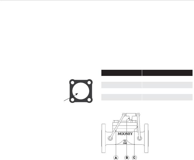
2.Pipe regulator with the inlet, outlet, and loading connections all common so that pressure is equalized in the entire regulator during the hydrostatic test (See Figure 8).
3.Refer to Table 4 for Maximum hydrostatic test pressure of each Flowgrid regulator.
4.After hydrostatic test is completed follow the Disassembly, Cleaning, and Assembly procedures in the Maintenance section of this manual.
Table 4 - Maximum Hydrostatic Test Pressures
End Connection |
Max. Hydrostatic Test Pressure |
Screwed & Socket Weld |
2225 psi (153.41 bar) |
150# Flange & Flangeless |
450 psi (31.02 bar) |
300# Flange & Flangeless |
1125 psi (77.56 bar) |
600# Flange & Flangeless |
2225 pis (153.4 bar) |
Flowgrid 2501 |
375 psi (25.86 bar) |
1 The Flowgrid 250 is a ductile iron construction.
Figure 8 - Flowgrid Tee Connections
A. Inlet connection on regulator body joined to “Tee”.
B.“Tee” connected to loading connection on spring case.
C.Outlet of “Tee” connected to outlet connection on regulator
5
 Loading...