


DVMRe Triplex

© 2004 GE Security
All Rights Reserved.
Any GE Security software supplied with GE Security products is proprietary and furnished under license and can be used or copied only in accordance with the terms of such license.
This document contains proprietary information that is protected by copyright. No part of this document may be reproduced or transmitted in any form or by any means without the prior written permission of GE Security.
The information contained in this document is subject to change without notice. GE Security in keeping pace with technological advances is a company of product innovation. Therefore, it is difficult to ensure that all information provided is entirely accurate and up-to-date. GE Security accepts no responsibility for inaccuracies or omissions and specifically disclaims any liabilities, losses, or risks, personal or otherwise, incurred as a consequence, directly or indirectly, of the use or application of any of the contents of this document.
For the latest product specifications, visit GE Security online at www.GE-Security.com or contact your GE Security sales representative.
For technical support before and after installation, call 800-469-1676.
Technical support is available 24 hours a day, 7 days a week.
Call: Tech Support 800-469-1676 (6 A.M. – 5 P.M. PST Monday through Friday)
Tech Support 541-740-3589 (all other times)
Main 800-343-3358 or 541-754-9133
Fax: Tech Support 541-752-9096 (available 24 hours a day)
Main |
541-754-7162 |
Web: www.ge-security.com
0150-0193G / April 2004
This equipment has been tested and found to comply with the limits for a Class A digital device, pursuant to part 15 of the FCC Rules. These limits are designed to provide reasonable protection against harmful interference when the equipment is operated in a commercial environment. This equipment generates, uses, and can radiate radio frequency energy and, if not installed and used in accordance with the instruction manual, may cause harmful interference to radio communications.
You are cautioned that any changes or modifications not expressly approved by the party responsible for compliance could void the user's authority to operate the equipment.
0150-0193G |
2 |
DVMRe Triplex |

Contents |
|
|
1 DVMRe Triplex Overview ...................................................................................... |
6 |
|
1.1 |
Products Featured In This Manual ................................................................................... |
6 |
1.2 |
Product Description.......................................................................................................... |
6 |
1.3 |
Passwords......................................................................................................................... |
7 |
1.4 |
Unpacking ......................................................................................................................... |
8 |
1.5 |
Installation Environment .................................................................................................. |
8 |
1.6 |
Associated Equipment...................................................................................................... |
9 |
1.7 |
The Back Panel ................................................................................................................. |
9 |
1.8 |
Power-Up......................................................................................................................... |
15 |
1.9 |
Minimum Recommended Menu Setup ........................................................................... |
16 |
2 DMVRe Triplex Basic Operations....................................................................... |
17 |
|
2.1 |
Principal Operating Modes ............................................................................................. |
17 |
2.2 |
The Front Panel............................................................................................................... |
17 |
2.3 |
Live Viewing .................................................................................................................... |
18 |
2.4 |
Playback.......................................................................................................................... |
19 |
2.5 |
Recording........................................................................................................................ |
21 |
2.6 |
Display Options............................................................................................................... |
22 |
2.7 |
Active Cameos ................................................................................................................ |
22 |
2.8 |
Sequencing ..................................................................................................................... |
23 |
2.9 |
On-screen Indicators ...................................................................................................... |
24 |
2.10 |
Triplex Mode ................................................................................................................... |
25 |
2.11 The Print Image Feature ................................................................................................. |
27 |
|
3 Menu System Overview....................................................................................... |
29 |
|
3.1 |
Menu Notation In This Manual........................................................................................ |
29 |
3.2 |
Accessing The Menu System ......................................................................................... |
29 |
3.3 |
Available Menus.............................................................................................................. |
29 |
3.4 |
Menus In This Manual..................................................................................................... |
30 |
3.5 |
Navigating The Menu System......................................................................................... |
30 |
3.6 |
Menu Shortcuts............................................................................................................... |
30 |
3.7 |
The Main Menu................................................................................................................ |
31 |
3.8 |
Time/Date ........................................................................................................................ |
31 |
3.9 |
Sequencing ..................................................................................................................... |
34 |
3.10 |
Record ............................................................................................................................. |
34 |
3.11 |
Alarms ............................................................................................................................. |
41 |
3.12 |
Macro............................................................................................................................... |
47 |
3.13 |
Motion Detection............................................................................................................. |
49 |
3.14 |
Camera Setup.................................................................................................................. |
52 |
3.15 |
Archive Setup.................................................................................................................. |
56 |
3.16 |
Audio Setup..................................................................................................................... |
56 |
0150-0193G |
3 |
DVMRe Triplex |
3.17 |
Communications............................................................................................................. |
57 |
3.18 |
Front Panel Lock............................................................................................................. |
60 |
3.19 |
Factory Settings.............................................................................................................. |
60 |
3.20 |
Passwords....................................................................................................................... |
60 |
3.21 |
The QuickInstall Menu .................................................................................................... |
62 |
3.22 |
The Operator Menu ......................................................................................................... |
62 |
3.23 |
The SystemView Menu.................................................................................................... |
63 |
4 Alarms .................................................................................................................. |
67 |
|
4.1 |
Alarm Input...................................................................................................................... |
67 |
4.2 |
Alarm Output................................................................................................................... |
67 |
4.3 |
Alarm Acknowledge........................................................................................................ |
67 |
4.4 |
On-screen Displays During Alarms................................................................................ |
67 |
4.5 |
Alarm Operations During Playback................................................................................ |
68 |
4.6 |
Alarm History Box........................................................................................................... |
69 |
4.7 |
Searching For Recorded Alarms .................................................................................... |
69 |
5 Searching ............................................................................................................. |
70 |
|
5.1 |
Disk Analysis Screen...................................................................................................... |
71 |
5.2 |
Quick Archive to CD ....................................................................................................... |
71 |
5.3 |
Motion Search ................................................................................................................. |
72 |
5.4 |
Search Filters .................................................................................................................. |
73 |
5.5 |
Retail Search ................................................................................................................... |
74 |
5.6 |
Search Results................................................................................................................ |
76 |
6 WebBrowser......................................................................................................... |
78 |
|
6.1 |
WaveBrowser Overview and Controls ........................................................................... |
79 |
6.2 |
DVMRe Triplex WaveLink ............................................................................................... |
81 |
7
8
Technical Specifications..................................................................................... |
83 |
|
RS232 Alarm/Event Generation/Text Insertion Protocol.................................. |
85 |
|
8.1 |
Message Structure.......................................................................................................... |
85 |
8.2 |
Message Type ................................................................................................................. |
85 |
8.3 |
Alarm/Event Fields.......................................................................................................... |
86 |
8.4 |
Alarm Actions ................................................................................................................. |
86 |
8.5 |
Event Actions.................................................................................................................. |
87 |
9 RS232 Remote Control Protocol ........................................................................ |
88 |
|
9.1 |
Front Panel Button Emulation........................................................................................ |
88 |
9.2 |
Configuration and Status ............................................................................................... |
89 |
|
|
|
0150-0193G |
4 |
DVMRe Triplex |

10Macro Tables........................................................................................................ |
90 |
|
10.1 |
Macro Functions Table ................................................................................................... |
90 |
10.2 |
Scheduled Macro Table .................................................................................................. |
91 |
11Warranty and Service.......................................................................................... |
92 |
|
11.1 |
Factory Service ............................................................................................................... |
92 |
11.2 |
Warranty and Return Information................................................................................... |
93 |
0150-0193G |
5 |
DVMRe Triplex |

1 DVMRe Triplex Overview
1.1 Products Featured In This Manual
DVMRe -4CT: Digital Video Multiplexer Recorder, Four-Channel, Color, Triplex.
DVMRe -10CT: Digital Video Multiplexer Recorder, Ten-Channel, Color, Triplex.
DVMRe -16CT: Digital Video Multiplexer Recorder, Sixteen-Channel, Color, Triplex.
Key To Model Numbers
1. |
DVMRe: Digital Video Multiplexer Recorder, Ethernet capable. |
|
DVMRe |
16 |
C |
T |
2. |
4, 10, or 16: Maximum number of camera inputs. |
|
|
|
|
|
|
1 |
2 |
3 |
4 |
||
3. |
C: Color. |
|
|
|
|
|
|
|
|
|
|
||
4. |
T: Triplex. |
|
|
|
|
|
1.2 Product Description
The DVMRe Triplex is a video multiplexer capable of recording from multiple cameras to one or more internal hard drives while simultaneously providing playback. Unlike outdated time-lapse VCRs, the DVMRe Triplex records high-resolution pictures. Digital recording improves playback quality over VCRs, and eliminates the hassle of cleaning heads, changing tapes or servicing motors. The unit can also be programmed to record continuously by overwriting the oldest recorded data. Depending on the setup, the DVMRe Triplex can store from a few hours to more than 3 years of color images.
Programmable search features eliminate time consuming Fast Forwarding or Rewinding of tapes, searching for critical data. Search for recorded images or events by alarm, time, date, motion, video loss, camera number and ASCII cash register or ATM text.
Caution! This products primary purpose is to furnish video multiplexing and recording. Although the unit has alarm handling and motion detection functions, they are considered secondary features. This unit should not be the only alarm device on site.
Features
∙Multiplexer functionality with built-in digital recording.
∙Triplex simultaneous recording, playback, and live multiscreen viewing.
∙Remote programming and control through the RS232, RS485 and Ethernet ports.
∙View live or recorded images remotely using WaveReader software.
∙Dual multiscreen monitor displays.
∙Auto-detect video mode on startup (NTSC or PAL).
∙Video motion detection (intrusion and activity).
∙Retail and Motion search.
∙Preview search results with thumbnail images.
∙Record speed selectable per camera.
∙Displays include full screen, sequenced, picture-in-picture, and multiscreens.
∙Alarm Handling with History Log. Preand post alarm recording, selectable per camera.
∙Archive onto GE Security DVSe Disk Array, or RAID, DAT, AIT, or CD-Rs.
∙IEEE 1394 Firewire interface for GE Security DVSe Disk Array or Firewire Disk Drives.
∙Continuous Recording with simultaneous Archiving.
∙PTZ control via ethernet or POTS, using CBR-KB3/J or KTD-405 keypad.
∙Covert camera recording (recording without display).
0150-0193G |
6 |
DVMRe Triplex |

∙Auto-Daylight savings time change function.
∙Clock synchronization with Network Server.
∙Alarm Notification via email and/or TCP/IP.
∙Integrated WaveBrowser Software.
∙Dynamic IP addressing (DHCP).
∙Support for Dynamic Domain Name Server (DDNS).
∙One-touch image printing directly from the DVMRe.
∙Support for over a dozen languages.
∙Hard Disk monitoring and testing features.
∙Playback and live audio via WaveReader on audio supported models.
1.3Passwords
Passwords are provided to limit access to menus and certain functions. Two levels of password security are provided:
∙Operator: Limited menu access, only Operator and System View menus are available.
∙Installer: Complete menu access.
As a security measure, it is recommended that the Operator and Installer passwords be changed after installation is complete (see section 3.20). Store the passwords in the administrator’s secure files.
Default Passwords
Four-Channel Units
|
Password |
|
|
Access |
|
|
|
|
|
Changeable |
|
|
Default |
|
|
Type |
|
|
Level |
|
|
Function |
|
|
by user? |
|
|
Password |
|
|
|
|
|
|
|
|
|
|
|
|
|
|
|
|
|
Operator |
|
|
Operator |
|
|
Provides access to the Operator |
|
|
Yes |
|
|
Press ‘ENTER’ |
|
|
|
|
|
|
and SystemView menus. |
|
|
|
|
4 Times |
|
|||
|
|
|
|
|
|
|
|
|
|
|
|
|
||
|
|
|
|
|
|
|
|
|
|
|
|
|
|
|
|
Installer |
|
|
Installer |
|
|
Provides access to all on-screen |
|
|
Yes |
|
3 4 4 4 |
|
|
|
|
|
|
|
menus. |
|
|
|
|
|||||
|
|
|
|
|
|
|
|
|
|
|
|
|
|
|
|
|
|
|
|
|
|
|
|
|
|
|
|
|
|
|
Factory |
|
|
|
|
|
Resets the multiplexer to the |
|
|
|
|
|
|
|
|
|
|
Installer |
|
|
factory defaults (except the time, |
|
|
No |
|
4 1 1 1 |
|
||
|
Defaults |
|
|
|
|
date, email addresses, and email |
|
|
|
|
||||
|
|
|
|
|
|
|
|
|
|
|
|
|
||
|
|
|
|
|
|
|
IP address). |
|
|
|
|
|
|
|
|
|
|
|
|
|
|
|
|
|
|
|
|
|
|
|
Language |
|
|
Installer |
|
|
Provides access to the On-screen |
|
|
No |
|
1 4 1 4 |
|
|
|
|
|
|
|
Language menu. |
|
|
|
|
|||||
|
|
|
|
|
|
|
|
|
|
|
|
|
|
|
|
|
|
|
|
|
|
|
|
|
|
|
|
|
|
|
Ethernet |
|
|
|
|
|
Deactivates the ethernet |
|
|
|
|
|
|
|
|
Access |
|
|
Installer |
|
|
password, so that the unit may be |
|
|
No |
|
1 1 1 1 |
|
|
|
|
|
|
|
accessed by any PC equipped with |
|
|
|
|
|||||
|
Reset |
|
|
|
|
|
|
|
|
|
|
|
|
|
|
|
|
|
|
|
WaveReader. |
|
|
|
|
|
|
|
|
|
|
|
|
|
|
|
|
|
|
|
|
|
|
|
0150-0193G |
7 |
DVMRe Triplex |

Ten and Sixteen-Channel Units
|
Password |
|
|
Access |
|
|
Function |
|
|
Changeable |
|
|
Default |
|
|
Type |
|
|
Level |
|
|
|
|
by user? |
|
|
Password |
|
|
|
|
|
|
|
|
|
|
|
|
|
|
|
|
|
|
Operator |
|
|
Operator |
|
|
Provides access to the Operator |
|
|
Yes |
|
|
Press ‘ENTER’ |
|
|
|
|
|
|
and SystemView menus. |
|
|
|
|
4 Times |
|
|||
|
|
|
|
|
|
|
|
|
|
|
|
|
||
|
|
|
|
|
|
|
|
|
|
|
|
|
|
|
|
Installer |
|
|
Installer |
|
|
Provides access to all on-screen |
|
|
Yes |
|
3 4 7 7 |
|
|
|
|
|
|
|
menus. |
|
|
|
|
|||||
|
|
|
|
|
|
|
|
|
|
|
|
|
|
|
|
|
|
|
|
|
|
|
|
|
|
|
|
|
|
|
Factory |
|
|
|
|
|
Resets the multiplexer to the |
|
|
|
|
|
|
|
|
|
|
Installer |
|
|
factory defaults (except the time, |
|
|
No |
|
8 1 1 1 |
|
||
|
Defaults |
|
|
|
|
date, email addresses, and email |
|
|
|
|
||||
|
|
|
|
|
|
|
|
|
|
|
|
|
||
|
|
|
|
|
|
|
IP address). |
|
|
|
|
|
|
|
|
|
|
|
|
|
|
|
|
|
|
|
|
|
|
|
Language |
|
|
Installer |
|
|
Provides access to the On-screen |
|
|
No |
|
5 4 1 5 |
|
|
|
|
|
|
|
Language menu. |
|
|
|
|
|||||
|
|
|
|
|
|
|
|
|
|
|
|
|
|
|
|
|
|
|
|
|
|
|
|
|
|
|
|
|
|
|
Ethernet |
|
|
|
|
|
Deactivates the ethernet |
|
|
|
|
|
|
|
|
Access |
|
|
Installer |
|
|
password, so that the unit may be |
|
|
No |
|
1 1 1 1 |
|
|
|
|
|
|
|
accessed by any PC equipped with |
|
|
|
|
|||||
|
Reset |
|
|
|
|
|
|
|
|
|
|
|
|
|
|
|
|
|
|
|
WaveReader. |
|
|
|
|
|
|
|
|
|
|
|
|
|
|
|
|
|
|
|
|
|
|
|
1.4 Unpacking
Check the package and contents for visible damage. If any components are damaged or missing, do not attempt to use the unit, contact the supplier immediately. If the unit must be returned, it must be shipped in the original packing box.
Package Contents
∙The DVMRe Triplex unit.
∙The Alarm Interface Circuit Board (P/N 0090-0077).
∙Accessory PCB (P/N 0900-0127). Audio equipped models only.
∙The User Manual (P/N 0150-0193).
∙A WaveReader Software CD (P/N 0151-0005-25W11).
∙The WaveReader Software Manual (P/N 0150-0143).
∙The Archiving Addendum (P/N 0150-0194).
∙WaveWatch User Manual (P/N 0150-0189).
∙Power Supply (P/N 4310-0020).
∙Power Cords (120 VAC P/N 4310-0002) and (220 VAC P/N 4310-0001).
1.5Installation Environment
Power: Ensure that the installation site’s AC power is stable and within the rated voltage of the 12 Volt DC power supply. If the site’s AC power is likely to have spikes or power dips, use power line conditioning or an Uninterruptable Power Supply (UPS).
Ventilation: Ensure that the location planned for the installation of the unit is well ventilated. Take note of the locations of the cooling vents in the unit’s enclosure, and ensure that they are not obstructed.
Temperature: Consider the unit’s operating temperature (0 to 40 °C) and non-condensing humidity specifications (10% to 80%) before choosing an installation location. Extremes of heat or cold beyond
0150-0193G |
8 |
DVMRe Triplex |
the specified operating temperature limits may cause the unit to fail. Do not install the unit on top of other hot equipment. Leave space between rack mounted units.
Moisture: Do not expose the unit to rain or moisture. Moisture can damage the internal components. Do not install the unit near sources of water.
Chassis: Other equipment may be placed on top of the unit if it weighs less than 35 pounds (16 kilograms).
1.6 Associated Equipment
Associated equipment in a typical security system could contain the following items:
∙Two monitors
∙A Keyboard (KB3 or KTD405).
∙Video cameras: Composite video, 1 volt peak-to-peak.
∙Alarm input devices: Pressure sensors, motion detectors, etc.
∙Alarm output devices: Buzzers, Sirens, Flashing Lights, etc.
∙A PC connected via ethernet cable.
∙An external archive device, such as a DVSe, RAID, CD-R, DAT, or AIT drive.
∙Printer with Printer Server connected via ethernet cable.
For instructions regarding the connection of the associated security equipment in your system, please consult the instruction manual of the associated equipment.
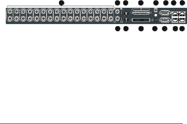
1.7 The Back Panel
|
|
|
|
|
|
|
|
1 |
|
|
|
|
|
|
2 |
3 |
4 |
5 |
6 |
7 |
8 |
|
|
|
|
|
|
|
|
|
|
|
|
|
|
|
|
|
|
|
AUX |
|
ETHERNET |
|
|
|
|
|
|
|
|
|
|
|
|
|
|
|
|
|
|
|
RS-485/1 |
10/100 |
|
|
|
|
|
|
|
|
|
|
|
|
|
|
|
|
|
|
|
|
|
||
1 |
2 |
3 |
4 |
5 |
6 |
7 |
8 |
9 |
10 |
11 |
12 |
13 |
14 |
15 |
16 |
|
|
12V DC |
|
|
|
SVHS |
|
|
RS-232/1 |
|
|
||||||||||||||||
|
|
|
|
|
|
|
|
|
|
|
|
|
|
|
|
|
|
|
|
||
|
|
|
|
|
|
|
|
|
|
|
|
|
|
|
|
|
SCSI |
|
|
|
|
|
|
|
|
|
|
|
|
|
|
|
|
|
|
|
|
|
IEEE-1394 |
|
|
|
|
|
|
|
|
|
|
|
|
|
|
|
|
|
|
|
B |
B |
|
|
|
|
|
|
|
|
|
|
|
|
|
|
|
|
|
|
|
|
|
|
|
|
|
RS-485/2 |
RS-232/2 |
|
|
|
|
|
|
|
|
|
|
|
|
|
|
|
9 |
10 |
11 |
12 |
13 |
14 |
15 |
1.Camera Inputs: BNC connector, looping. Auto Terminating.
2.Composite Monitor-A Output: Composite video output with BNC style connector.
3.Y/C Monitor-A Output: Y/C video output with 4-pin mini-DIN style connector.
4.Alarm I/O: For connecting alarm inputs, and alarm output relays.
5.Power Input: For connecting the power supply.
6.Aux Port: For connecting the Accessory PCB for Audio inputs and outputs.
7.RS485 Port 1 Connector: For connecting to keyboard and other RS485 devices.
8.10/100 Ethernet Port: For connecting to remote PC via ethernet network.
9.Composite Monitor-B Output: Composite video output with BNC style connector.
10.Y/C Monitor-B Output: Y/C video output with 4-pin mini-DIN style connector.
11.SCSI Port: For connecting SCSI compatible archive devices.
12.IEEE 1394 Firewire Port: For connecting Firewire compatible archive devices.
13.RS232 Port 1: For modem connection and external control of the unit.
0150-0193G |
9 |
DVMRe Triplex |
14.RS485 Port 2 Connector: For connecting to keyboard and other RS485 devices.
15.RS232 Port 2: For Event Generation and ASCII Text insertion.
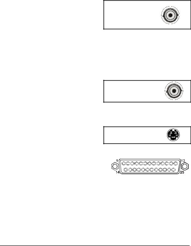
Camera Inputs
There are two BNC jacks for each camera. Either jack can receive a camera signal. The signal is looped (directly connected to the other jack), making the camera signal available to other equipment.
The camera input connectors are Auto Terminating.
Cable: 75-Ohm Coaxial
Connectors: BNC
Auto Terminating: Yes
Passive Looping: Yes
This means that the input signal will automatically be terminated with 75-Ohms unless a 2nd cable is connected to the 2nd BNC connector of the same camera input. Make sure there is 75-Ohm termination at the end of the video line if the signal is looped through the DVMRe Triplex.
Time base correction is performed during digital capture. As a result, cameras do not require synchronization.
See section 3.14 for information about disabling unused camera jacks in the menu system.
Composite Monitor Output
When connecting directly from the DVMRe Triplex to the monitor, select the 75-Ohm impedance setting on the monitor.
Cable: 75-Ohm Coaxial
Connectors: BNC
If an additional device is connected to the monitor’s looping output, set the termination of the additional device as 75-Ohm, and set the termination of the monitor as Hi-Z (High Impedance).
Y/C Monitor Output
Y/C video output has a 4-pin mini-DIN style connector. This style of connection is also referred to as SVHS and S-Video.
Cable: 75-Ohm Coaxial
Connectors: BNC
Alarm I/O Port
The back panel of the unit is equipped with an Alarm
Port (DB-25 style connector).
Do not attempt to wire directly to the DB-25 |
DB-25 Connector on Back Panel |
connector on the back panel. |
Connect the Alarm PCB (supplied with the unit) to the Alarm Port. Wire all alarm inputs to the Alarm PCB per the pin out specifications shown below.
0150-0193G |
10 |
DVMRe Triplex |
Pin 1: Alarm Input 1. |
Pin 13: Alarm Input 13. |
Pin 2: Alarm Input 2. |
Pin 14: Alarm Input 14. |
Pin 3: Alarm Input 3. |
Pin 15: Alarm Input 15. |
Pin 4: Alarm Input 4. |
Pin 16: Alarm Input 16. |
Pin 5: Alarm Input 5. |
Pin 17: Alarm Output Relay #1. |
Pin 6: Alarm Input 6. |
Pin 18: Ground. |
Pin 7: Alarm Input 7. |
Pin 19: Ground. |
Pin 8: Alarm Input 8. |
Pin 20: Ground. |
Pin 9: Alarm Input 9. |
Pin 21: Alarm Output Relay #1 Common. |
Pin 10: Alarm Input 10. |
Pin 22: Alarm Output Relay #2. |
Pin 11: Alarm Input 11. |
Pin 23: External Alarm Silence and Acknowledge Input. |
Pin 12: Alarm Input 12. |
Pin 25: Alarm Output Relay #2 Common. |
Signal |
PIN |
PIN |
Signal |
A1 |
1 |
13 |
A13 |
A14 |
14 |
25 |
COM2 |
A2 |
2 |
12 |
A12 |
A15 |
15 |
24 |
Vext |
A3 |
3 |
11 |
A11 |
A16 |
16 |
23 |
ACK |
A4 |
4 |
10 |
A10 |
NO1 |
17 |
22 |
NO2 |
A5 |
5 |
9 |
A9 |
GND |
18 |
21 |
COM1 |
A6 |
6 |
8 |
A8 |
GND |
19 |
20 |
GND |
A7 |
7 |
20 |
GND |
Alarm PCB
Active alarm inputs vary by DVMRe model. 4 channel units (4CT) have 4 active alarm inputs. 10 channel units (10CT) have 10 active alarm inputs.
Alarm Input
An alarm condition can be activated by devices such as pressure pads, passive infrared detectors, door switches, or other similar devices.
See section 3.11 for information about configuring the contacts as Normally Open or Normally Closed in the menu system.
Normally Open, Zero Potential Relay Contact: Configure in menu as Normally Open.
Normally Closed, Zero Potential Relay Contact: Configure in menu as Normally Closed
TTL Active High: Configure in menu as Normally Closed. |
High: 5V (12V Tolerant) |
TTL Active Low: Configure in menu as Normally Open. |
Low: Ground |
Open Collector Active On: Configure in menu as Normally Open. |
Inputs: 1 per channel. |
Open Collector Active Off: Configure in menu as Normally Closed. |
|
|
DVMRe Triplex DB25 Connector
Alarm Input No. 1 |
pin 1 |
|
|
|
|
|
|
|
Alarm Input No. 2 - 15 |
pins 2-15 |
|
|
|
|
|
|
|
Alarm Input No. 16 |
pin 16 |
|
|
|
|
|
|
|
Ground |
pins 18-20 |
|
Typical wiring for Alarm #1 as Normally Open and Alarm #16 as Normally Closed.
Normally Open
(Closes During Alarm)
Typical Alarm Device
Refer to each alarm device's manual for specific wiring details.
Normally Closed
(Opens During Alarm)
Typical Alarm Device
Normally Open and Normally Closed Connections
0150-0193G |
11 |
DVMRe Triplex |
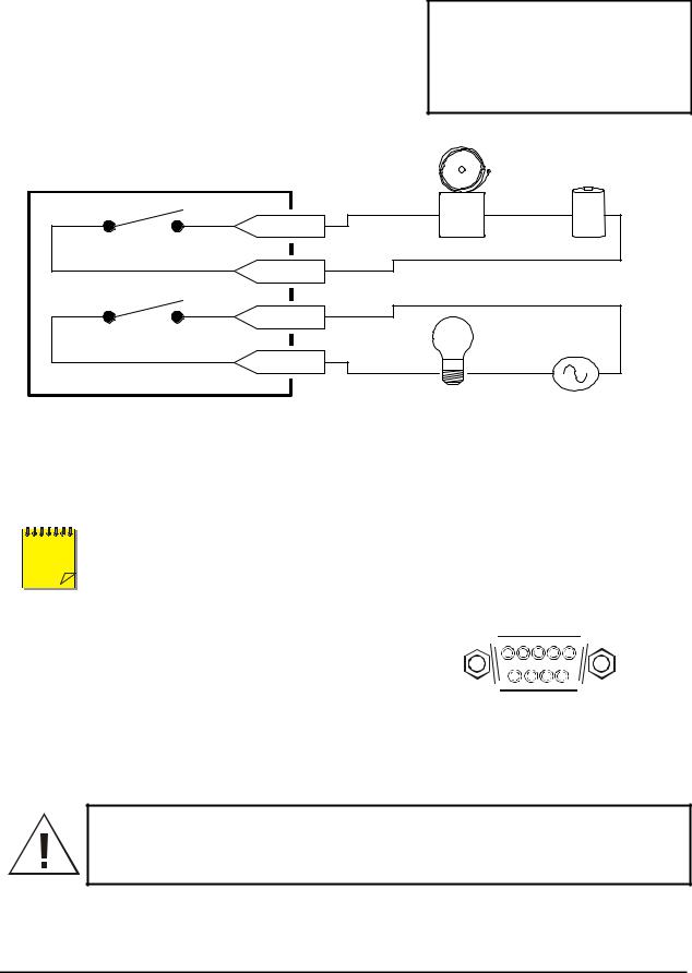
Alarm Relay Output
The alarm relay output is activated when an alarm condition exists. The alarm output is only active for the duration of the alarm.
Alarm relays can be programmed in the menu system to respond to macros, and video loss. See section 3.11 for information about configuring the alarms in the menu system.
Typical wiring for Alarm Relays. Relays may be programmed Normally Open or Normally Closed.
Output: Zero potential relay contacts, programmable in menu system as Normally Open or Normally Closed.
Voltage: 30V (Max)
Current: 500mA (Max)
pin 17
Output Relay No. 1
pin 21
Alarm |
Power |
Device |
Source |
pin 22 |
|
Power |
|
Output Relay No. 2 |
Controlled |
||
Source |
|||
pin 25 |
Device |
|
DVMRe Triplex DB25 Connector
External Alarm Acknowledge Input
Connect a switch or similar device to ground this pin in order |
External Device: Normally Open |
|||
to acknowledge an alarm condition, and silence associated |
Zero potential relay contact. |
|||
buzzers and relays. Connect from pin 23 to either pin 18, 19, |
|
|||
|
||||
or 20 (ground pins). |
|
|||
NOTE |
|
|||
All specifications subject to change without notice. GE Security believes all specifications |
||||
to be correct at time of printing, but no liability is assumed for omissions or errors. |
||||
|
|
|
|
|
|
|
|
|
|
|
|
|
|
|
|
|
|
|
|
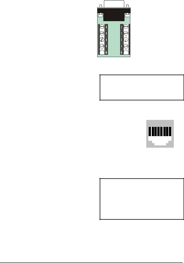
AUX Port
The back panel of the unit is equipped with an Aux Port (DB-9 style connector).
Do not attempt to wire directly to the DB-9 connector on the back panel.
1 

 5
5
6 
 9
9
DB-9 Connector on Back Panel
Connect the Accessory PCB (supplied with the audio equipped models) to the AUX port to access the Audio features. Wire the audio input and output to the Accessory PCB per the pin out specifications shown below.
Warning! The use of clandestine listening and recording devices is forbidden by Federal Law as well as other State and Municipal Jurisdictions. Please review local and Federal Law prior to the installation or operation of this equipment to ensure that you are in legal compliance with the Authorities having Jurisdiction.
0150-0193G |
12 |
DVMRe Triplex |
Pin 1: Not Used.
Pin 2: Audio Out.
Pin 3: Ground.
Pin 4: Audio In.
Pin 5: Ground.
Pin 6: Not Used.
Pin 7: Ground.
Pin 8: Not Used.
Pin 9: Ground.
GND: Ground.
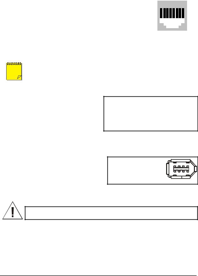
RS485 Connector
Shields are grounded at one end, preferably at the DVMRe Triplex.
See section 3.17 for information about configuring the RS485 network address settings in the menu system.
1 |
6 |
2 |
7 |
3 |
8 |
4 |
9 |


 5 GND
5 GND 


Accessory PCB
Wire Type: #24 AWG, twisted pair with shield (2-wire)
Connector Type: RJ-45
Max. Cable Length: 3200 feet / 1000 meters
RJ-45 Pin Configuration For RS485 Port
|
Pin |
|
|
Use |
|
|
|
Pin |
|
|
Use |
|
|
|
|
|
|
|
|
|
|
|
|
|
|
|
|
|
|
|
|
|
|
|
|
1 2 3 4 5 6 7 8 |
|
|
|||||||||||||
|
1 |
|
|
Ground (Shield) |
|
|
5 |
|
|
Not Connected |
|
|
|
|
|
|
|
|
|
|
|
|
|
|
|
|
|
|
|
|
|
|
|
|
|
|
|
|
|
|
|
|
|
|
|
|
|
|
|
|
|
|
2 |
|
|
Not Connected |
|
|
6 |
|
|
Network -VE |
|
|
|
|
|
|
|
|
|
|
|
|
|
|
|
|
|
|
|
|
|
|
|
|
|
|
|
|
|
|
|
|
|
|
|||||||
|
|
|
|
|
|
|
|
|
|
|
|
|
|
|
|
|
|
|
|
|
|
|
|
|
|
|
3 |
|
|
Network +VE |
|
|
7 |
|
|
Ground (Shield) |
|
|
|
|
|
|
|
|
|
|
|
|
|
|
|
|
|
|
|
|
|
|
|
|
|
|
|
|
|
|
|
|
|
|
|||||||
|
|
|
|
|
|
|
|
|
|
|
|
|
|
|
|
|
|
|
|
|
|
|
|
|
|
|
|
|
|
|
|
|
|
|
|
|
|
|
|
|
|
|
|
|
|
|
|
|
|
|
|
|
4 |
|
|
Not Connected |
|
|
8 |
|
|
Not Connected |
|
RJ-45 socket on |
|||||||||||||
|
|
|
|
|
|
|
|
|
|
|
|
|
|||||||||||||
|
|
|
|
|
|
|
|
|
|
|
|
|
|
back panel. |
|||||||||||
Ethernet Port
The cable connection configuration depends on your network configuration:
∙For a DVMRe Triplex that connects directly to a Hub or Switch, use a straight through connection.
∙For a DVMRe Triplex that connects directly to a PC, use a cross over connection.
Consult with your MIS personnel for the specific type of configuration. See section 3.17 for information about configuring the ethernet settings in the menu system.
Wire Type: Cat 5
Connector Type: RJ-45
Max. Cable Length: 100 meters / 328 ft.
Min. Cable Length: 6 feet / 1.8 meters
Hub Wiring Configuration: Straight Through
PC Wiring Configuration: Cross Over
0150-0193G |
13 |
DVMRe Triplex |
RJ-45 Pin Configuration For Ethernet Port
|
Pin |
|
|
Use |
|
|
|
Pin |
|
|
Use |
|
|
|
|
|
|
|
|
|
|
|
|
|
|
|
|
|
|
|
|
|
|
|
|
1 2 3 4 5 6 7 8 |
|
|
|||||||||||||
|
1 |
|
|
TX+ |
|
|
5 |
|
|
Not Connected |
|
|
|
|
|
|
|
|
|
|
|
|
|
|
|
|
|
|
|
|
|
|
|
|
|
|
|
|
|
|
|
|
|
|
|
|
|
|
|
|
|
|
2 |
|
|
TX- |
|
|
6 |
|
|
RX- |
|
|
|
|
|
|
|
|
|
|
|
|
|
|
|
|
|
|
|
|
|
|
|
|
|
|
|
|
|
|
|
|
|
|
|||||||
|
|
|
|
|
|
|
|
|
|
|
|
|
|
|
|
|
|
|
|
|
|
|
|
|
|
|
3 |
|
|
RX+ |
|
|
7 |
|
|
Not Connected |
|
|
|
|
|
|
|
|
|
|
|
|
|
|
|
|
|
|
|
|
|
|
|
|
|
|
|
|
|
|
|
|
|
|
|||||||
|
|
|
|
|
|
|
|
|
|
|
|
|
|
|
|
|
|
|
|
|
|
|
|
|
|
|
|
|
|
|
|
|
|
|
|
|
|
|
|
|
|
|
|
|
|
|
|
|
|
|
|
|
4 |
|
|
Not Connected |
|
|
8 |
|
|
Not Connected |
|
RJ-45 socket on |
|||||||||||||
|
|
|
|
|
|
|
|
|
|
|
|
|
|||||||||||||
|
|
|
|
|
|
|
|
|
|
|
|
|
|
back panel. |
|||||||||||
NOTE |
SCSI and IEEE 1394 archiving devices should not be connected to the DVMRe Triplex |
||
simultaneously. Archiving support is only available for one or the other type of interface at a |
|||
|
|
|
time. |
|
|
|
|
|
|
|
|
|
|
|
|
SCSI Port
The unit is equipped with a SCSI port for connecting external archive devices. The unit only supports a single SCSI device. The SCSI ID of the archive device must be set to 0.
The SCSI bus must be terminated, otherwise the system will not operate properly.
Additional menu setup may be necessary to configure archive device. See section 3.15.
Connector: 50 Pin, High Density SCSI-2.
Gender (on unit) : Female
Compatible devices : DVSe, RAID, DAT, AIT, CD-R, CD-RW
SCSI ID : 0
IEEE 1394 Firewire Port
The unit is equipped with an IEEE 1394 Firewire port for connecting Firewire compatible external archive devices. For information on the approved devices, please refer to the Archiving Addendum manual that is supplied with this unit.
Cable: 6 position Firewire
Connectors: 6 position DIP
Caution! Ensure the power to DVMRe Triplex is OFF BEFORE connecting any SCSI or 1394 devices. Do not attempt to use the SCSI and 1394 ports simultaneously.
0150-0193G |
14 |
DVMRe Triplex |
RS232 Port 1
For a Modem connection or remote control of unit. See section 3.17 for information about configuring the modem settings in the menu system. See section 9 for RS232 Remote Control Protocols.
DB-9 Pin Configuration For Port 1
|
Pin |
|
|
Use |
|
|
|
Pin |
|
|
Use |
|
|
|
Pin |
|
|
Use |
|
1 |
5 |
|
|
|
|
|
|
|
|
|
|
|
|
|
|
|
|
||||||
|
|
|
|
|
|
|
|
|
|
|
|
|
|
|
|
|
|
|
|
|
|
|
1 |
|
|
DCD |
|
|
4 |
|
|
DTR |
|
|
7 |
|
|
RTS |
|
6 |
9 |
||
|
|
|
|
|
|
|
|
|
|
|
|
|
|
|
|
|
|
|
|
||
|
2 |
|
|
RX |
|
|
5 |
|
|
Ground |
|
|
8 |
|
|
CTS |
|
DB-9 on back panel. |
|||
|
3 |
|
|
TX |
|
|
6 |
|
|
Not Connected |
|
|
9 |
|
|
Not Connected |
|
|
|
||
|
|
|
|
|
|
|
|
|
|
|
|
|
|
|
|
|
|
|
|
|
|
RS232 Port 2
For Event Generation and ASCII Text Insertion.
RJ-45 Pin Configuration For RS232 Port 2
|
Pin |
|
|
Use |
|
|
|
Pin |
|
|
Use |
|
|
|
|
|
|
|
|
|
|
|
|
|
|
|
|
|
|
|
|
|
|
|
|
1 2 3 4 5 6 7 8 |
|
|
|||||||||||||
|
1 |
|
|
Ground |
|
|
5 |
|
|
TXD |
|
|
|
|
|
|
|
|
|
|
|
|
|
|
|
|
|
|
|
|
|
|
|
|
|
|
|
|
|
|
|
|
|
|
|
|
|
|
|
|
|
|
2 |
|
|
Reserved |
|
|
6 |
|
|
Not Connected |
|
|
|
|
|
|
|
|
|
|
|
|
|
|
|
|
|
|
|
|
|
|
|
|
|
|
|
|
|
|
|
|
|
|
|||||||
|
|
|
|
|
|
|
|
|
|
|
|
|
|
|
|
|
|
|
|
|
|
|
|
|
|
|
3 |
|
|
Not Connected |
|
|
7 |
|
|
Ground |
|
|
|
|
|
|
|
|
|
|
|
|
|
|
|
|
|
|
|
|
|
|
|
|
|
|
|
|
|
|
|
|
|
|
|||||||
|
|
|
|
|
|
|
|
|
|
|
|
|
|
|
|
|
|
|
|
|
|
|
|
|
|
|
|
|
|
|
|
|
|
|
|
|
|
|
|
|
|
|
|
|
|
|
|
|
|
|
|
|
4 |
|
|
RXD |
|
|
8 |
|
|
Reserved |
|
RJ-45 socket on |
|||||||||||||
|
|
|
|
|
|
|
|
|
|
|
|
|
|||||||||||||
|
|
|
|
|
|
|
|
|
|
|
|
|
|
back panel. |
|||||||||||
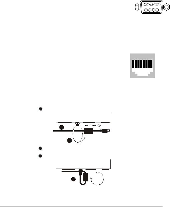
1.8 Power-Up
Use the diagram below to secure the power cord to the back panel.
1Slide approximately 6 inches of the power cord through the pre-installed cable tie (approximately 1 inch after the ferrite core).
1
2
2Tighten the cable tie until the cord is secure. Do not over tighten.
3Loop the power cord end around and insert into the power receptacle on the back panel.
3
It is important that the power-up procedures be followed carefully. The unit uses its auto-detect feature to detect camera signals during power-up, and configure itself automatically.
0150-0193G |
15 |
DVMRe Triplex |

Power-up procedure
Once the system installation is complete, apply power in the following order:
1.Energize the monitors and all of the cameras.
2.Energize the DVMRe Triplex.
Power Supply Input
Voltage: 12 Volt DC
Power: 60 Watt (5 Amp)
Connector: 2.1mm barrel, center positive
Once power is applied to the unit, it will begin its power-up procedure. The unit will begin by displaying the software version on Monitor-A, then the unit will begin recording automatically.
Check Video Input Quality
Check the picture quality by selecting each camera for full screen display. If the picture quality is poor, check the following items:
∙The BNC connections.
∙The loop-through terminations.
∙The video levels of incoming signals.
∙The possibility of ground loops.
∙Consult the camera’s installation instructions for additional information about proper camera setup.
Check Record And Playback Quality
Record for at least three minutes at the default record rate. Then play back the recording, selecting each camera for full screen display. Check the playback picture quality.
1.9 Minimum Recommended Menu Setup
After installation is complete, it is strongly recommended that, as a minimum, the items in the QuickInstall menu be configured before the unit is used. All the features located in the QuickInstall menu are also found in the Main menu. These items are provided in the separate QuickInstall menu as a convenience for the installer.
For information about accessing and configuring the menu system, see Section 3.
To find detailed information in this manual about configuring each item in the QuickInstall menu, use the following table to locate the main menu location of each item in the QuickInstall menu.
|
QuickInstall |
Main Menu Location |
Section in |
|
|
Menu Item |
|
Manual |
|
|
Change the time |
Main Menu → Time/Date → Set Time |
3.8 |
|
|
|
|
|
|
|
Change the date |
Main Menu → Time/Date → Set Date |
3.8 |
|
|
|
|
|
|
|
Edit Camera |
Main Menu → Camera Setup → Camera Titles → Edit Titles |
3.14 |
|
|
Titles |
|
|
|
|
|
|
|
|
|
Camera Disable |
Main Menu → Camera Setup → Camera Disable |
3.14 |
|
|
|
|
|
|
|
Record Quality |
Main Menu → Record → Record Quality |
3.10 |
|
|
|
|
|
|
|
Installer |
Main Menu → Passwords → Installer Password |
3.20 |
|
|
Password |
|
|
|
|
|
|
|
|
|
Auto Disable |
Main Menu → Camera Setup → Camera Disable → Auto |
3.14 |
|
|
Now |
Disable Now |
|
|
|
|
|
|
|
|
|
|
|
|
0150-0193G |
16 |
DVMRe Triplex |
2 DMVRe Triplex Basic Operations
2.1 Principal Operating Modes
The DVMRe Triplex has three principal modes of operation:
∙Live Viewing.
∙Playback.
∙Recording.
All three of these modes can operate simultaneously. Each mode is discussed in detail later in this section.
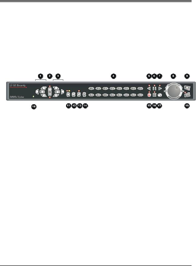
2.2 The Front Panel
1.Multiscreen Selection Buttons: 16, 10, 7, and 4 way.
2.Monitor Selection Button: Monitor A or Monitor B.
3.Multiscreen Selection Buttons: 13, 9, 6 way, and Picture-in-Picture.
4.Camera Selection Number buttons: Camera numbers 1 through 16.
5.Reverse Play Button: Playback in Reverse.
6.Freeze Button: Freezes camera images on-screen in Live mode. Pauses Playback.
7.Play Forward Button: Begins Playback.
8.Jog/Shuttle: Controls Playback speed and Menu selections.
9.Menu Button: Provides access to on-screen menus.
10.Power Indicator: Indicates power on/off condition.
11.Alarm button: Allows user to acknowledge and silence alarms.
12.Sequence Button: Sequences camera views.
13.Zoom Button: Provides a 2X digital zoom.
14.Function Button: Used in conjunction with Camera Buttons to run Macros.
15.Record Button: Used to Start and Stop Recording.
16.Stop Button: To stop Playback and return to Live mode.
17.Search Button: Access to stored video data.
18.Enter Button: Confirms selection in menus.
0150-0193G |
17 |
DVMRe Triplex |
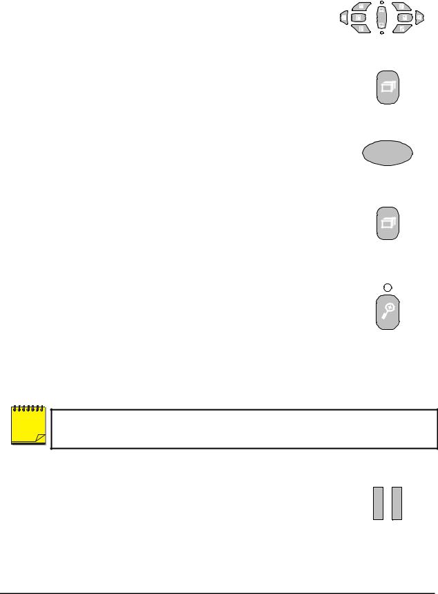
2.3 Live Viewing
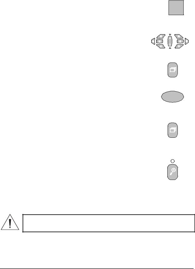
Multiscreen Display
In Live Multiscreen mode, press one of the Multiscreen buttons to activate the multiscreen display on Monitor-A or Monitor-B. Live Multiscreens are displayed with gray borders. For detailed information about Multiscreen displays, see section 2.6.
A
B
Multiscreen Buttons
Multiscreen Display With Sequencing
If a multiscreen display does not include all of the cameras, the remaining
cameras can be sequenced in the bottom right cameo. While in a multiscreen display, press the Sequence button to begin sequencing. For detailed
information about sequencing, see section 2.8.
Sequence Button
Full Screen Display
Select any camera for Full Screen display by pressing the Number button of the desired camera. Pressing the Camera number button again displays the Status Display Box. Pressing the same button a third time displays any associated ATM or cash register ASCII text, see section 2.9.
1
Number Button
Sequenced Full Screen Display
While in a Full Screen display, press the Sequence button to begin full |
|
|
screen sequencing. The sequence list and dwell times are programmable. |
|
|
For detailed information about programming the sequence list see section |
|
|
2.8. For detailed information about configuring the dwell times in the menu |
Sequence Button |
|
system, see section 0. |
||
|
Zooming
To activate the 2x digital zoom, select the full screen display of the camera you wish to zoom, then press the Zoom button. Zooming will be indicated by the LED located directly above the Zoom button. Zooming is also indicated as ZOOM on the primary monitor. Zooming works with frozen and non-frozen images. Zoomed images can also be frozen.
While Zoomed, rotate the Jog/Shuttle to Pan and Tilt across the image. Please note, the camera does not move during digital Pan/Tilt.
Press the Zoom button again to cancel the Zoom operations.
Zoom Button
with LED
NOTE |
If the Zoom button is pressed while in a multiscreen display, the camera from the last active cameo is selected for full screen display. Press the Zoom button again to activate the Zoom operation.
Freezing
Pressing the Freeze button freezes all camera images on-screen. Full Screen freezing is indicated as FRZ on-screen. Multiscreen freezing is indicated as * (a flashing asterisk) in each frozen cameo.
Individual cameos can be frozen in Active Cameo mode (see section 2.7). Freeze Button
Press the Freeze button again or any camera button to cancel Freeze operations.
0150-0193G |
18 |
DVMRe Triplex |

Selecting Monitor-B
To control Monitor-B, press the lower part of the Monitor button. The Monitor-B LED will light to indicate that the number keypad now controls Monitor-B. Press the upper part of the Monitor button again to return the keypad control to Monitor-A.
2.4 Playback
A
B
Monitor Button
Playback always displays on Monitor A. Playback multiscreen borders are black, as opposed to the gray borders of the live multiscreens. Monitor B continues to display full or multiscreen live images in playback mode. To begin playback, press the Play Forward or Reverse Play button.
Play Forward
When the Play Forward button is pressed, the unit will play forward at the rate the data was recorded. While in Playback mode, the user may change the playback direction, playback speed, etc. To return to Play Forward operations,
press the Play Forward button.
Play Forward
Button
Reverse Play
To begin reverse playback, press the Reverse Play button.
Reverse Play
Button
Fast Forward
During playback, rotate the Shuttle (the outer dial) clockwise to view data at a higher than normal rate. Increasing the amount of rotation increases the rate of playback.
AutoPause
Jog / Shuttle
During playback, moving the Jog (the inner dial) in any direction will freeze playback. Depress the Freeze or any Play button to continue playback.
Rewind
During playback, rotate the a higher than normal rate. playback.
Shuttle counter-clockwise to view data (in reverse) at Increasing the amount of rotation increases the rate of
Freeze
During playback, press the Freeze button. This feature pauses all full screen and multiscreen images
Freeze Button
Single Frame Advance & Single Frame Rewind
During Freeze or Pause mode, rotate the Jog (the inner dial) to view the frame directly before or after the frame displayed on-screen.
0150-0193G |
19 |
DVMRe Triplex |
Stop Playback
To stop playback and return to Live Multiscreen mode on Monitor A, press the Stop button.
Stop Button
Multiscreen Display
During Playback, press one of the Multiscreen buttons to activate a multiscreen display. The 6-way and PIP multiscreen displays are not available in Playback mode. For detailed information about Multiscreen displays, see section 2.6.
A
B
Multiscreen Buttons
Multiscreen Display With Sequencing
If a multiscreen display does not include all of the cameras, the remaining cameras can be sequenced in the bottom right cameo. While in a multiscreen display, press the Sequence button to begin sequencing. For detailed information about sequencing, see section 2.8.
Full Screen Display
Select any camera for Full Screen display by pressing the Number button of the desired camera. Pressing the Camera number button again displays the Status Display Box. Pressing the same button a third time displays any associated ATM or cash register ASCII text.
Sequence Button
1
Number Button
Sequenced Full Screen Display
While in a Full Screen display, press the Sequence button to begin full |
|
|
screen sequencing. The sequence list and dwell times are programmable. |
|
|
For detailed information about programming the sequence list see section |
|
|
2.8. For detailed information about configuring the dwell times in the menu |
Sequence Button |
|
system, see section 0. |
||
|
Zooming
To activate the 2x digital zoom, select the full screen display of the camera you wish to zoom, then press the Zoom button. Zooming will be indicated by the LED located directly above the Zoom button. Zooming is also indicated as ZOOM on the monitor. Zooming works with frozen and non-frozen images. Zoomed images can also be frozen.
While Zoomed, use the Jog/Shuttle to Pan and Tilt across the image. Please note, the camera does not move during digital Pan/Tilt.
Press the Zoom button again, or another camera button to cancel the Zoom operations.
Zoom Button
with LED
If the Zoom button is pressed while in a multiscreen display, the camera from the last active cameo is selected for full screen display. Press the Zoom button again to activate the Zoom operation.
Searching Recorded Data
The DVMRe Triplex has a powerful search interface feature that allows the user to search for data on the internal hard disk or an external archive device. The user may search the data for previous recording sessions, retail data, text insertion, alarm conditions, or for motion in a selectable area of the
0150-0193G |
20 |
DVMRe Triplex |
scene. Because the search interface is so dynamic, the search interface is covered in detail in a separate section of this manual. See section 5.
2.5 Recording
To begin recording, press the Record button. Recording will be indicated by the LED located directly above the Record button. The unit always starts recording at the end of previously recorded data.
The unit will continue recording until the record button is pressed again. Record Button
Monitor Displays During Recording
Multiscreen Live and Playback displays on Monitor A and Monitor B are not affected by recording operations.
Monitor A
LIVE
PLAY |
BACK |
LIVE |
PLAY |
BACK |
Monitor B |
||
LIVE |
or |
LIVE |
LIVE |
or |
LIVE |
LIVE |
0150-0193G |
21 |
DVMRe Triplex |
2.6 Display Options
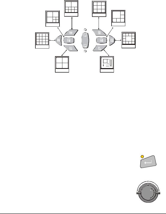
Available Multiscreen Displays
Press the Multiscreen buttons to activate the multiscreen display. Pressing the individual multiscreen button will display the corresponding multiscreen.
10-Way |
7-Way |
16-Way
4-Way |
|
9-Way |
Monitor A |
6-Way |
AA |
|
BB |
13-Way |
|
|
Monitor B |
|
|
PIP |
The multiscreen display is limited to the number of camera inputs on the unit.
Sixteen-Channel unit: Capable of displaying all multiscreens.
Ten-Channel unit: Only capable of displaying 10-way through 4-way multiscreen and PIP.
Four-Channel unit: Only capable of displaying 4-way multiscreen and PIP.
The camera assignments for each multiscreen is retained (in non-volatile memory) for both Live and Playback multiscreen mode on Monitor A, as well as Live multiscreen mode on Monitor B.
PIP: Use the Jog/Shuttle to adjust the location and size of the PIP display. Please note that the PIP display is only available on Monitor A in Live mode, when Monitor B is in fullscreen display mode.
2.7 Active Cameos
A cameo is defined as any cell within a multiscreen display. Active Cameo mode allows the user to access and edit each cameo individually.
Entering Active Cameo Mode
While viewing a multiscreen, enter Active Cameo mode by pressing the Enter button. Active Cameo mode is indicated on-screen by flashing the number and titles of the active cameo and the LED above the Enter button is lit. By
default, the top left cameo is activated.
Enter Button
Selecting Cameos
Select a cameo using the Jog/Shuttle to navigate the multiscreen. Rotating the Jog selects the next screen up or down a row. Rotating the shuttle selects the next screen in numerical order. The active cameo will always be indicated by the flashing camera number and titles.
Jog/Shuttle
0150-0193G |
22 |
DVMRe Triplex |
Selecting Cameras
Display any camera in the active cameo by pressing the Number button of the desired camera. Once a camera has been selected, the active cameo advances to the next cameo on the right.
1
Number Button
The camera selection only changes the multiscreen currently being displayed. Each multiscreen must be configured separately. Changes to the multiscreen display are saved in non-volatile memory, and will be retained even if power is removed from the unit.
Freezing
Press the Freeze button to freeze the image in the selected cameo. Each frozen cameo is indicated as * (a flashing asterisk) on-screen.
Press the Freeze button again to cancel Freeze operations.
Freeze Button
2.8 Sequencing
The sequencing feature allows a camera to be displayed briefly on-screen, before advancing to the next camera in the sequence list. The default sequence list displays each camera in numerical order.
Sequence Button
Dwell Time
The dwell time is the amount of time each camera is displayed on-screen before advancing to the next camera. The Full Screen and Multiscreen Dwell Times are separately programmable in the menu system. For detailed information about configuring the dwell times in the menu system, see section 0.
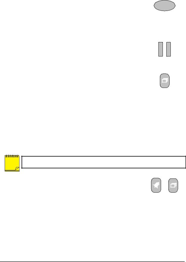
Autolist™ Custom Sequence List
The Autolist™ feature allows the user to create a custom sequence list, controlling the order the cameras are displayed and the dwell time. Separate Autolists may be created for Monitor A (Live and Playback mode) and Monitor B (Live mode). Using the Monitor button, select the monitor to be programmed. Then, using a Number button, select any camera for full screen display.
NOTE |
The unit must be in Full Screen Display mode before starting to create the sequence list. This initial camera is not part the sequence list.
To begin recording the Autolist™ sequence: Press the Alarm button and
Sequence button simultaneously. Autolist Program mode is indicated as PGM on-screen.
Recording starts when the first camera number is pressed. Press the camera numbers in the order you wish them to appear on-screen. The amount of time between button presses determines the Dwell Time. During sequence list programming, pressing any button other than a Number button or the Sequence button voids the sequence list.
Alarm Button and
Sequence Button
To end the recording: Number button and the sequence list.
Press the Sequence button. The amount of time between pressing the last Sequence button determines the dwell time for the final camera in the
Returning To The Default Sequence List
The default sequence list is all cameras in numeric order with a three second dwell time.
0150-0193G |
23 |
DVMRe Triplex |

To return the unit to the default sequence list, go to the Main Menu → Sequencing → Full Screen Dwell menu. Select 03 seconds by rotating the Jog, then press the Enter button.
Note: Any alteration of the dwell time from this menu will cancel the sequence list and return to the default (numeric) order.
Sequencing In Cameos
While viewing a multiscreen display, additional cameras (cameras not shown in the multiscreen display) can be sequenced in the lower right hand cameo by pressing the Sequence button. The sequence list is not programmable, but the dwell time can be adjusted in the menu system. Press the Sequence button again to cancel sequencing.
2.9 On-screen Indicators
There are five types of on-screen indicators.
Camera Titles: Displays the camera number and the camera title.
Status Indicators: Displays Time, Date, and Hard Disk record time left.
Conditional Indicators: Displays indicators for Freeze, Zoom, Alarm, Motion Detection, Videoloss, Autolist™ Program mode, Macro Record and Macro Playback mode.
Status Display Box: Displays Archive Device, Network status and Image Quality Setting (Playback mode only).
Text Display Box: Displays ATM/POS Text data.
Camera Titles
Camera Titles are displayed on either the upper or lower corner of the left hand side of the screen. The camera title can be changed in the menu system (see section 3.14). The user can change display position and color. See below.
Changing Position And Color Of Title And Status Indicators
Camera Titles: To change the color and position of the camera titles, select a camera for full screen display, then press the Enter button to advance to the next display setting. Repeatedly pressing the Enter button advances the display settings through the sequence show in the table on the right.
Example: Select Camera 1 for full screen display. Using the Enter button, cycle through the sequence shown on the right. Each time the position cycle is completed, the unit advances the Status Indicator color. Choose Black, White or Gray.
|
Position |
Color |
|
|
|
|
|
|
Top Left |
Black |
|
|
|
|
|
|
Top Left |
White |
|
|
|
|
|
|
Top Left |
Gray |
|
|
|
|
|
|
Bottom Left |
Black |
|
|
|
|
|
|
Bottom Left |
White |
|
|
|
|
|
|
Bottom Left |
Gray |
|
|
|
|
|
Title not displayed
Status Indicators
Status indicators are displayed on the upper right hand corner of the screen.
Status indicators include:
∙ Time and Date (these can be turned off in the menu system, see
section 3.8). The Time and Date format can also be changed in Small Cameo the menu system.
∙Time remaining on Hard Disk(s).
0150-0193G |
24 |
DVMRe Triplex |

Conditional Indicators
Condition |
Full Screen Indicator |
Multiscreen Indicator |
|
|
|
Alarm |
ALM |
A in cameo of camera in alarm |
|
|
|
Autolist™ Program |
PGM |
PGM |
mode |
|
|
|
|
|
Freeze |
FRZ |
* (Asterisk) in frozen cameo |
Macro Record mode |
F followed by macro number |
F followed by macro number |
|
|
|
Motion Detection |
M |
M in cameo w/ motion detection |
|
|
|
Videoloss |
VDL |
V in cameo with videoloss |
|
|
|
Zoom |
ZOOM |
ZOOM |
|
|
|
Status Display Box
A Status Display Box can be viewed by pressing the Camera Number button twice. Status Indicators include:
On Live Fullscreen:
∙Archive Status: Not Connected, Not Ready, Ready, Ejecting, Play, and timeleft. Timeleft indicates the amount of time before the archive medium is full (Only available if the unit has Background Archiving turned On).
∙Network: Displays all current Network connections. Normal connection is displayed as ip.ip or ---
if there is no connection. Live connections are displayed as E1: ip.ip, E2: ip.ip, etc. (where ip.ip represents the last 2 bytes of the IP Address). POTS connection is displayed as IP 1.1.
On Playback Fullscreen:
∙All the above, including Image Quality Setting: High, Medium, Standard.
ATM/POS Text Display
Pressing the Camera Number a third time displays an ATM/POS text display. This feature can be used during live viewing mode to verify that the DVMRe Triplex is receiving ATM/POS text, or in Playback mode to review recorded text and video.
2.10 Triplex Mode
Triplex mode allows the display of both live and playback images to appear on Monitor A simultaneously. Live images have gray borders, while playback images have black borders.
To enter Triplex mode, press the Play Forward button while in Play Forward mode. Alternatively, press the Play Reverse button while in Play Reverse mode. Both the Play Forward LED and the Stop LED turn on to indicate that the unit is in Triplex mode.
Monitor B always switches to a fullscreen live display whenever Triplex mode is entered.
Play Forward
When in Play Forward mode and the Play Forward button is pressed, the unit will enter the Triplex mode of operation. When Play Forward is pressed again, the unit will revert back into the normal Playback mode. While in the Triplex mode, if reverse play is in progress, the Play Forward button will change the playback direction.
Play Forward
Button
0150-0193G |
25 |
DVMRe Triplex |

Reverse Play
When in Reverse Play mode and the Reverse Play button is pressed, the unit will enter the Triplex mode of operation. When Reverse Play is pressed again, the unit will revert back into the normal Playback mode. While in the Triplex mode, if forward play is in progress, the Reverse Play button will change the playback direction.
Fast Forward
During Triplex mode, rotate the Shuttle (the outer dial) clockwise to view playback images at a higher than normal rate. Increasing the amount of rotation increases the rate of playback. Live images are not affected.
Rewind
During Triplex mode, rotate the Shuttle counter-clockwise to view playback images (in reverse) at a higher than normal rate. Increasing the amount of rotation increases the rate of playback. Live images are not affected.
Freeze
During Triplex mode, pressing the Freeze button pauses all multiscreen images, both Live and Playback.
Single Frame Advance & Single Frame Rewind
During Freeze or Pause mode, rotate the Jog (the inner dial) to view the frame directly before or after the frame displayed on-screen. Only the playback images are affected.
Stop
To stop Triplex mode and return to Live mode on Monitor A, press the Stop button.
Reverse Play
Button
Jog / Shuttle
Freeze Button
Stop Button
Multiscreen Display
During Triplex mode, press one of the Multiscreen buttons to activate a multiscreen display. The 6-way and PIP multiscreen displays are not available in Triplex mode. For detailed information about Multiscreen displays, see section 2.6. The Live and Playback images in a multiscreen display may be transposed by pressing the multiscreen button that corresponds with the current multiscreen display.
A
B
Multiscreen Buttons
E.g. If the current display is a 13-way multiscreen with the center cameo being a playback image and the rest of the cameos being live images, pressing the 13-way multiscreen button will result in the center cameo being live and the rest of the cameos being playback images.
0150-0193G |
26 |
DVMRe Triplex |

Multiscreen Display With Sequencing
The bottom right cameo of any multiscreen will start sequencing when the
Sequence button is pressed. If this camera is a playback image, the sequencing will include all the non-displayed playback cameras, and vice
versa for a live image.
Sequence Button
Full Screen Display
Select any camera for Full Screen display by pressing the Number button of the desired camera. Pressing the Camera number button again displays the Status Display Box. Pressing the same button a third time displays any associated ATM or cash register ASCII text.
Sequenced Full Screen Display
While in a Full Screen display, press the Sequence button to begin full screen sequencing. The sequence list and dwell times are programmable. For detailed information about programming the sequence list see section 2.8. For detailed information about configuring the dwell times in the menu system, see section 0.
1
Number Button
Sequence Button
Zooming
To activate the 2x digital zoom, select the full screen display of the camera you wish to zoom, then press the Zoom button. Zooming will be indicated by the LED located directly above the Zoom button. Zooming is also indicated as ZOOM on the monitor. Zooming works with frozen and non-frozen images. Zoomed images can also be frozen.
While Zoomed, use the Jog/Shuttle to Pan and Tilt across the image. Please note, the camera does not move during digital Pan/Tilt.
Press the Zoom button again, or another camera button to cancel the Zoom operations.
Zoom Button
with LED
NOTE |
If the Zoom button is pressed while in a multiscreen display, the camera from the last active |
||
cameo is selected for full screen display. Press the Zoom button again to activate the Zoom |
|||
|
|
|
operation. |
|
|
|
|
|
|
|
|
|
|
|
|
|
|
|
|
2.11 The Print Image Feature
Pressing the Function and Zoom button will print the currently displayed image. If any multiscreen is the display mode, the Triplex will switch to a single image display of the last selected fullscreen camera, freeze the image, and send to the default printer.


 {F}
{F} 
Zoom and Function
Button
0150-0193G |
27 |
DVMRe Triplex |

Printer Setup
The following equipment and conditions are required for the operation of the Print Image feature.
Equipment
HP DeskJet 3820
Hawking Print Server PN7127P
Conditions
The Printer and Print Server must be connected to the same local network as the Triplex.
The Triplex must be aware of the Print Server’s IP address. The IP address can be input under Main Menu – Communications – Ethernet – Ethernet Settings (See Section 3.15).
The Printer and Print Server must be On-line and Operational.
0150-0193G |
28 |
DVMRe Triplex |
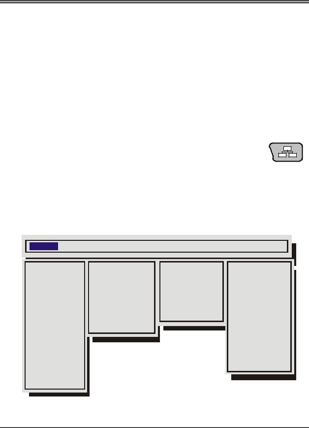
3 Menu System Overview
3.1 Menu Notation In This Manual
In the following sections, there are headings like this:
qMain Menu → Time/Date → Set Time
Meaning: From the Main Menu, select Time/Date, then press the Enter button. The Time/Date menu will appear. From the Time/Date menu, select Set Time, then press the Enter button. A pop-up or pull-down menu will appear.
Selected Items
Items selected in the menu system are represented in the manual as follows:
Selected |
|
Not Selected |
Time/Date |
|
Time/Date |
|
|
|
3.2 Accessing The Menu System
Enter the menu system by pressing the Menu button. A Password Box will appear on the primary monitor. Enter either the:
∙Operator Password: Providing limited access to the menu system. Only the
Operator and System View menus are available. Menu Button
∙ Installer Password: Providing complete menu access. Use the Number buttons to enter the appropriate password.
Default passwords are provided in the beginning of this manual, in section 1.
3.3 Available Menus
Main |
QuickInstall |
Operator |
SystemView |
|
Time/Date |
|
Change the time |
Sequencing |
About DVMR |
|
|
|
|
|
Sequencing |
|
Change the date |
Time/Date Display |
View Screen 1 |
Record |
|
Edit Camera Titles |
Titles Display |
View Screen 2 |
|
|
|
|
|
Alarms |
|
Camera Disable |
Alarm History |
View Screen 3 |
|
|
|
|
|
Macro |
|
Record Quality |
Archive Setup |
View Screen 4 |
Motion Detection |
|
Installer Password |
Operator Password |
View Screen 5 |
|
|
|
|
|
Camera Setup |
|
Auto Disable Now |
|
View Screen 6 |
Archive Setup |
|
|
|
View Screen 7 |
Audio Setup |
|
|
|
View Screen 8 |
|
|
|
|
View Screen 9 |
Communications |
|
|
|
|
Front Panel Lock |
|
|
|
View Screen 10 |
Factory Settings |
|
|
|
|
Passwords |
|
|
|
|
0150-0193G |
29 |
DVMRe Triplex |
 Loading...