


GE JV247, JV248, JN327, JN328, JV338 Owner’s Manual & Installation Instructions
...<![endif]>RANGE HOODS
SAFETY INFORMATION . . . . . . . . . . . 3
USING THE HOOD
Controls . . . . . . . . . . . . . . . . . . . . . . . . . . . . . . . . 5
CARE AND CLEANING
Filters . . . . . . . . . . . . . . . . . . . . . . . . . . . . . . . . . . 6
Surfaces . . . . . . . . . . . . . . . . . . . . . . . . . . . . . . . . 6
Lights . . . . . . . . . . . . . . . . . . . . . . . . . . . . . . . . . . 7
INSTALLATION INSTRUCTIONS . . 8
TROUBLESHOOTING TIPS. . . . . . . . 17
LIMITED WARRANTY . . . . . . . . . . . . . 18
ACCESSORY . . . . . . . . . . . . . . . . . . . . . . . 19
CONSUMER SUPPORT . . . . . . . . . . . . 20
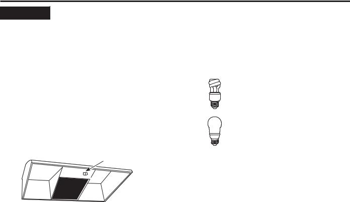
Write the model and serial numbers here:
Model #_________________
Serial # _________________
You can find them on a label on the back wall of the hood.
OWNER’S MANUAL &
INSTALLATION
INSTRUCTIONS
JV247*–Vent & Recirculation options JV248*–Vent & Recirculation options JN327–Recirculation only JN328–Recirculation only JV338*–Vent options only
JV347*–Vent & Recirculation options
JV348*–Vent & Recirculation options JV367*–Vent & Recirculation options RN328–Recirculation only AV447*–Vent & Recirculation options
ESPAÑOL
Para consultar una version en español de este manual de instrucciones, visite nuestro sitio de internet GEAppliances.com.
GE is a trademark of the General Electric Company. Manufactured under trademark license.
49-80589-8 06-20 GEA

THANK YOU FOR MAKING GE APPLIANCES A PART OF YOUR HOME.
Whether you grew up with GE Appliances, or this is your first, we’re happy to have you in the family.
We take pride in the craftsmanship, innovation and design that goes into every GE Appliances product, and we think you will too. Among other things, registration of your appliance ensures that we can deliver important product information and warranty details when you need them.
Register your GE appliance now online. Helpful websites and phone numbers are available in the Consumer Support section of this Owner’s Manual. You may also mail in the pre-printed registration card included in the packing material.
2 |
|
49-80589-8 |
IMPORTANT SAFETY INFORMATION READ ALL INSTRUCTIONS BEFORE USING
 WARNING TO REDUCE THE RISK OF FIRE, ELECTRIC SHOCK OR INJURY TO PERSONS, OBSERVE THE FOLLOWING:
A.Use this unit only in the manner intended by the manufacturer. If you have questions, contact the manufacturer.
B.Before servicing or cleaning unit, switch power off at service panel and lock the service disconnecting means to prevent power from being switched
on accidentally. When the service disconnecting means cannot be locked, securely fasten a prominent warning device, such as a tag, to the service panel.
C.Do not use this unit with any solid-state speed control device.
D.This unit must be grounded.
 CAUTION FOR GENERAL VENTILATING USE ONLY. DO NOT USE TO EXHAUST HAZARDOUS OR EXPLOSIVE MATERIALS AND VAPORS.
 WARNING TO REDUCE THE RISK OF INJURY TO PERSONS IN THE EVENT OF A RANGE TOP GREASE FIRE, OBSERVE THE FOLLOWING*:
A.SMOTHER FLAMES with a close-fitting lid, cookie sheet or metal tray, then turn off the burner. BE CAREFUL TO PREVENT BURNS. If the flames do not go out immediately, EVACUATE AND CALL THE FIRE DEPARTMENT.
B.NEVER PICK UP A FLAMING PAN—You may be burned.
C.DO NOT USE WATER, including wet dishcloths or towels—a violent steam explosion will result.
D.Use an extinguisher ONLY if:
1.You know you have a Class ABC extinguisher, and you already know how to operate it.
2.The fire is small and contained in the area where it started.
3.The fire department is being called.
4.You can fight the fire with your back to an exit.
*Based on “Kitchen Fire Safety” published by NFPA.
 CAUTION TO REDUCE RISK OF FIRE AND
TO PROPERLY EXHAUST AIR, BE SURE TO DUCT
AIR OUTSIDE. DO NOT VENT EXHAUST AIR INTO
SPACES WITHIN WALLS OR CEILINGS OR INTO
ATTICS, CRAWL SPACES OR GARAGES.
READ AND SAVE THESE INSTRUCTIONS
<![endif]>INFORMATION SAFETY
49-80589-8 |
3 |
<![endif]>SAFETY INFORMATION
IMPORTANT SAFETY INFORMATION READ ALL INSTRUCTIONS BEFORE USING
 WARNING TO REDUCE THE RISK OF A RANGE TOP GREASE FIRE:
A.Never leave surface units unattended at high settings. Boilovers cause smoking and greasy spillovers that may ignite. Heat oils slowly on medium settings.
B.Always turn hood ON when cooking at high heat or when flambéing food (i.e. Crepes Suzette, Cherries Jubilee, Peppercorn Beef Flanbé).
C.Clean ventilating fans frequently. Grease should not be allowed to accumulate on fan or filter.
D.Use proper pan size. Always use cookware appropriate for the size of the surface element.
 WARNING TO REDUCE THE RISK OF FIRE, ELECTRIC SHOCK OR INJURY TO PERSONS, OBSERVE THE FOLLOWING:
A.Installation work and electrical wiring must be done by qualified person(s) in accordance with all applicable codes and standards, including fire-rated construction.
B.Sufficient air is needed for proper combustion and exhausting of gases through the flue (chimney) of fuel burning equipment to prevent back drafting. Follow the heating equipment manufacturer’s guidelines and safety standards such as those published by the National Fire Protection Association (NFPA), the American Society for Heating, Refrigeration and Air Conditioning Engineers (ASHRAE) and the local code authorities.
C.When cutting or drilling into wall or ceiling, do not damage electrical wiring and other hidden utilities.
D.Ducted fans must always be vented to the outdoors.
E.When applicable, install any makeup (replacement) air system in accordance with local building code requirements. Visit GEAppliances.com for available makeup air solutions.
F.Turn off breaker to adjacent rooms while working.
 WARNING TO REDUCE THE RISK OF FIRE, USE ONLY METAL DUCTWORK.
ŶDo not attempt to repair or replace any part of your hood unless it is specifically recommended in this manual. All other servicing should be referred to a qualified technician.
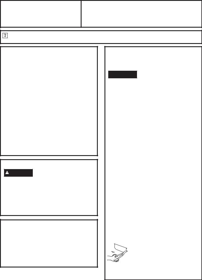
How to Remove Protective Shipping Film and Packaging Tape
Carefully grasp a corner of the protective shipping film |
To assure no damage is done to the finish of the |
with your fingers and slowly peel it from the appliance |
product, the safest way to remove the adhesive from |
surface. Do not use any sharp items to remove the film. |
packaging tape on new appliances is an application of |
Remove all of the film before using the appliance for the |
a household liquid dishwashing detergent. Apply with a |
first time. |
soft cloth and allow to soak. |
|
NOTE: The adhesive must be removed from all parts. |
READ AND SAVE THESE INSTRUCTIONS
4 |
49-80589-8 |
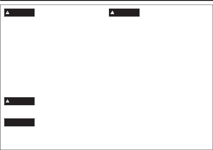
Controls
Throughout this manual, features and appearance may vary from your model.
Control Knobs (on some models) |
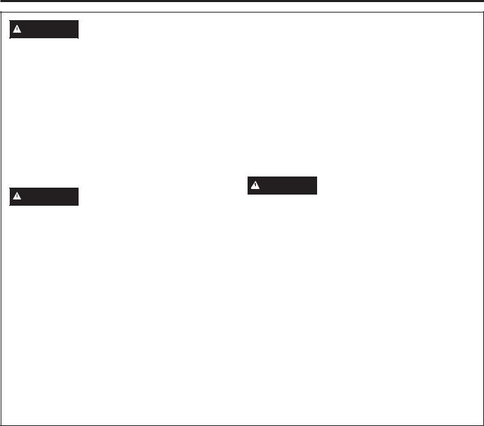
Switch Pad Controls (on some models) |
|
OFF |
OFF |
LO |
HI |
ON |
|
MED |
NITE |
|
1 |
2 |
|
OFF |
OFF |
|
HI |
ON |
|
MED |
NITE |
|
LO |
|
(AV447 models only)
12
1.FAN Control: Turn to HI, MED or LO as needed.
Continuous use of the fan system while cooking helps keep the kitchen comfortable and less humid. It also reduces cooking odors and soiling moisture that create a frequent need for cleaning.
2. LIGHT Control: Turn to ON while cooking or to NITE for use as a night light.
ON |
HI |
|
OFF |
OFF |
LO |
12
1.LIGHT Control: Press the pad at the top to turn
the light ON.
2. Fan Settings Buttons: Press the pad at the top to turn the fan on HI and at the bottom to turn it on LO. The center position is OFF.
Continuous use of the fan system while cooking helps keep the kitchen comfortable and less humid. It also reduces cooking odors and soiling moisture that create a frequent need for cleaning.
<![endif]>Controls HOOD: THE USING
49-80589-8 |
5 |
<![endif]>CARE AND CLEANING: Filters / Surfaces
Filters
Be sure electrical power is off and all surfaces are cool before cleaning or servicing any part of the vent hood.
Reusable Metal Grease Filter—Ducted Installations Only
The efficiency of your hood depends on a clean filter. Frequency of cleaning depends on hood use and the type of cooking you do. However, the grease filter should be cleaned at least once a month.
To remove:
Pull down on the center of the front edge of the filter. The filter will then slip out of the retaining tabs on the back.
To replace:
Slip the back edge of the filter into the retaining tabs and push the front edge up until it snaps into place.
To clean:
Soak and then agitate it in a hot water and detergent solution. Light brushing can be used to remove embedded dirt. Rinse, shake and let it dry before replacing.
NEVER OPERATE THE HOOD WITHOUT THE FILTER IN PLACE.
With careful handling, the metal filter will last for years. If a new replacement filter becomes necessary, order the part from your dealer. Order genuine GE Appliances part number WB02X8391.
Grease filter
Charcoal Filter—Recirculating Installations Only
The charcoal filter cannot be cleaned. It must be replaced. Order filter no. WB02X10700. Replacement filters can be ordered from your GE Appliances supplier.
If the hood is not vented to the outside, the air will be recirculated through a disposable charcoal filter that helps remove smoke and odors.
The charcoal filter should be replaced after 6 to 12 months (depending on hood usage).
To remove:
Pull down on the center of the front edge of the filter. The filter will then slip out of the retaining tabs on the back.
To replace:
Slip the back edge of the filter into the retaining tabs and push the front edge up until it snaps into place.
Replaceable charcoal filter
NOTE: DO NOT rinse, or put charcoal filters in an automatic dishwasher.
Surfaces
Stainless Steel Surfaces (on some models)
Do not use a steel-wool pad; it will scratch the surface.
To clean the stainless steel surface, use warm sudsy water or a stainless steel cleaner or polish. Always wipe the surface in the direction of the grain. Follow the cleaner instructions for cleaning the stainless steel surface.
To inquire about purchasing stainless steel appliance cleaner or polish, or to find the location of a dealer nearest you, please call our toll-free number:
National Parts Center 800.626.2002 GEApplianceParts.com
Painted Surfaces (on some models)
Do not use steel-wool pads or other abrasive cleaners. They will scratch the surface.
Clean grease-laden surfaces of the hood frequently. To clean the hood surface, use a hot, damp cloth with a mild detergent suitable for painted surfaces. About one tablespoon of ammonia may be added to the water. Use a clean, hot, damp cloth to remove soap. Dry with a dry, clean cloth.
NOTE: When cleaning, take care not to come in contact with filters and other non-enameled surfaces.
 CAUTION When cleaning the hood surfaces, be certain that you do not touch the light bulb with moist hands or cloth. A warm or hot light bulb may break if touched with a moist surface. Always let the light bulb cool completely before cleaning around it.
6 |
49-80589-8 |
Light
 CAUTION Let the light bulb cool completely before removing. A warm or hot bulb may break if touched with a moist cloth or hand.
Remove the bulb and replace it with a type A15 incandescent light bulb with an ordinary screw base, not more than 60 Watts, or a type A17 or T2 Compact
Fluorescent (CFL) light bulb with an ordinary screw base, not more than 13 Watts. NOTE: Use only incandescent bulbs in models RN328, JN327, JN328 and JV338.
IMPORTANT: For installation, handling and disposal precautions, refer to the fluorescent bulb packaging literature.
To remove the light cover (on some models):
Ŷ 3UHVV WKH VLGHV ZLWK WZR ILQJHUV XQWLO WKH VLGH SURQJV are released.
Ŷ /LIW WKH OLJKW FRYHU DQG VOLGH LW WRZDUG \RX LQ RQH motion.
Light cover
To replace the light cover:
Ŷ ,QVHUW WKH SURQJ ORFDWHG DW WKH HQG RI WKH FRYHU LQWR the top opening.
Ŷ *HQWO\ SXVK WKH FRYHU XS DQG SUHVV WKH VLGHV WR ILW the side prongs into the side openings.
Ŷ 5HOHDVH DQG WKH FRYHU ZLOO ORFN LQ SRVLWLRQ
When using an energy saving bulb in your GE
Appliances hood make sure you use either:
GE Long Life Energy Smart™
Spiral® T2
Product Code: 85383
Description: FLE13HT2/2/SW/CD
or
GE Long Life Energy Smart™ A17
Product Code: 47486
Description: FLE11/2/A17XL/CD
Available at gelighting.com
<![endif]>Light CLEANING: AND CARE
49-80589-8 |
7 |
<![endif]>INSTALLATION INSTRUCTIONS
InstallationInstructions Range Hood
“If you have questions, call GE Appliances at 800.GE.CARES (800.432.2737) or visit our website at: GEAppliances.com”
BEFORE YOU BEGIN
Read these instructions completely and carefully.
• IMPORTANT — Save these instructions for local inspector’s use.
• IMPORTANT — Observe all governing codes and ordinances.
•Note to Installer – Be sure to leave these instructions with the Consumer.
•Note to Consumer – Keep these instructions for future reference.
•Skill level – Installation of this vent hood requires basic mechanical and electrical skills.
•Proper installation is the responsibility of the installer.
•Product failure due to improper installation is not covered under the Warranty.
FOR YOUR SAFETY:
 WARNING Before beginning the installation, switch power off at service panel and lock the service disconnecting means to prevent power from being switched on accidentally. When the service disconnecting means cannot be locked, securely fasten a prominent warning device, such as a tag, to the service panel.
OPTIONAL POWER CORD KIT JXHC1
An optional Power Cord Connection Kit, model JXHC1, is available at extra cost from your GE Appliances supplier for installation using a standard 3-prong, grounded wall outlet. Follow the Installation Instructions packed with the kit to connect the power cord to the range hood.
DUCTWORK REQUIREMENTS
NOTE: Read the ductwork sections only if you do not have existing ductwork. If you have existing ductwork, skip to the “Damage” section and proceed.
 WARNING TO REDUCE THE RISK OF FIRE AND TO PROPERLY EXHAUST AIR, BE SURE TO DUCT AIR OUTSIDE—DO NOT VENT EXHAUST AIR INTO SPACES WITHIN WALLS OR CEILINGS OR INTO ATTICS, CRAWL SPACES OR GARAGES.
The venting system must exhaust to the outside.
This hood can be vented vertically through upper cabinets or horizontally through an outside wall. Ductwork is not included.
Exhaust connection:
The hood exhaust has been designed to mate with
VWDQGDUG » Ǝ [ Ǝ UHFWDQJXODU GXFWLQJ RU Ǝ GLDPHWHU round ducting.
,I D Ǝ URXQG GXFW LV UHTXLUHG D UHFWDQJXODU WR URXQG transition adaptor must be used*. Do not use less than D Ǝ diameter duct.
Duct length:
It is important that ducting be installed using the most direct route and with as few elbows as possible. This ensures clear venting of exhaust and helps prevent blockages. Also, make sure dampers swing freely and nothing is blocking the ducts. When applicable, install any makeup (replacement) air system in
accordance with local building code requirements. Visit GEAppliances.com for available makeup air solutions.
•Plan the route for venting exhaust to the outdoors. To maximize the ventilation performance of the vent system:
1.Minimize the duct run length and number of transitions and elbows.
2.Maintain a constant duct size.
3.Seal all joints with duct tape to prevent any leaks.
4.Do not use any type of flexible ducting.
•Install a wall cap or roof cap with damper at the exterior opening. Purchase the wall or roof cap and any transition and length of duct needed in advance.
*IMPORTANT: If a rectangular-to-round transition adaptor is used, the bottom

 corners of the damper will have to be cut to fit, using the tin snips, in order to allow free movement of the damper. Equivalent lengths of duct pieces are based on actual tests and reflect requirements for good venting performance with any hood.
8 |
49-80589-8 |
Installation Instructions
DAMAGE – SHIPMENT/
INSTALLATION
•If the unit is damaged in shipment, return the unit to the store in which it was bought for repair or replacement.
•If the unit is damaged by the customer, repair or replacement is the responsibility of the customer.
•If the unit is damaged by the installer (if other than the customer), repair or replacement must be made by arrangement between customer and installer.
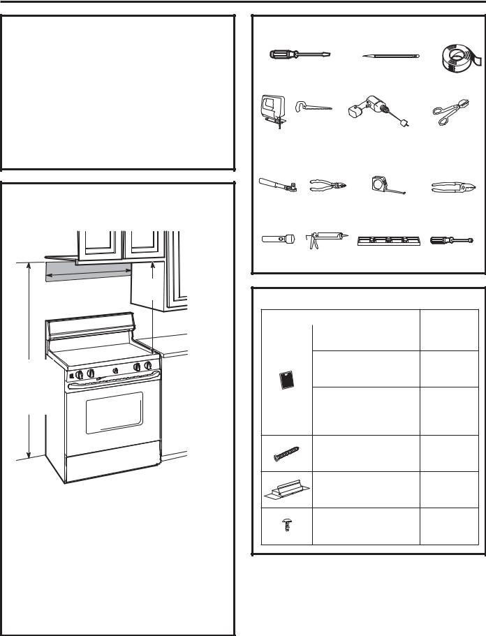
MOUNTING SPACE
s or |
36s |
24s, 30 |
|
to match cooktop |
|
width |
|
Bottom edge of cabinet needs to be 30s or more from the cooking  surface
30s min.
66s or more from the floor to the top of the hood
NOTES:
•Hood width may be greater than the width of the range or cooktop, but it may not be smaller.
•Ensure the range or cooktop is installed per manufacturer’s installation instructions.
•If you are going to vent your range hood to the outside, see the “Ducting Requirements” section for exhaust duct preparation.
•The hoods are designed to fit 12” deep cabinets. When installed onto 15” deep cabinets, a filler panel accessory is available: Order JXS50SS for 30” wide hoods or JXS56SS for 36” wide hoods.
TOOLS YOU WILL NEED |
|
||
Flat-blade and Phillips |
Pencil |
Duct tape |
|
screwdrivers |
|
||
Saw (saber or |
Electric drill |
Metal snips |
|
keyhole) |
|
(in some |
|
|
|
|
applications) |
1/4s |
Pliers |
Tape measure |
Wire |
pivoting |
|
|
stripper |
hex socket |
|
|
|
Flashlight |
Caulking |
Level |
1/4s Nutdriver |
PARTS INCLUDED
PART |
|
QUANTITY |
|
Grease Filter only |
1 |
|
(JV338) |
|
|
|
Charcoal Filter only
(JN327, JN328 and 1 RN328)
Grease Filter and
Charcoal Filter 2
(JV24X, JV347, JV348,
JV367 and AV447)
Mounting Screws
(8 - 18" x 3/4" Phillips 4 pan head)
Exhaust Adaptor
(for 3 1/4" x 10" rect. 1 venting)
Exhaust Adaptor Screw
(8 - 18" x 3/8" Phillips 1 pan head or hex head)
<![endif]>INSTRUCTIONS INSTALLATION
49-80589-8 |
9 |
<![endif]>INSTALLATION INSTRUCTIONS
10
Installation Instructions
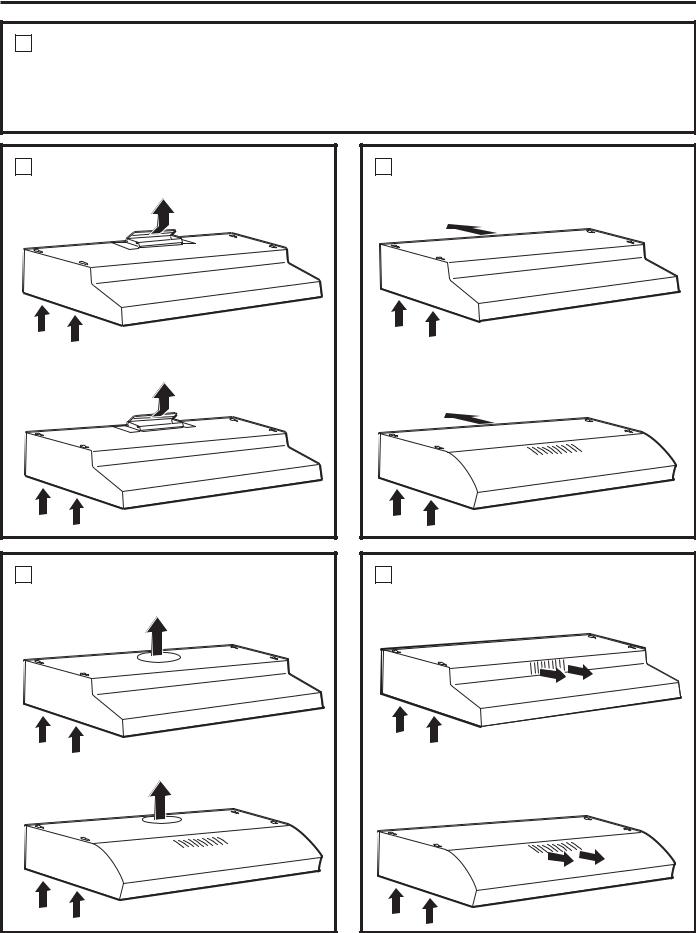
1 CHOOSE VENT OPTION
Determine the vent option that your installation |
IMPORTANT: If the hood is to be installed in a |
will require and that is available for your model |
recirculating, non-vented, ductless manner, do not |
from the below choices. |
knock out any vent openings in the hood. Only an |
|
electrical access hole will be knocked out of the hood. |
A Outside top exhaust |
(Vertical duct–3-1/4" x 10" Rectangular) |
JV338 |
JV247 |
JV248 |
JV347 |
JV348 |
JV367 |
AV447 |
B Outside top exhaust |
(Vertical duct–7" Round) |
JV338 |
JV247 |
JV248 |
JV347 |
JV348 |
JV367 |
AV447 |
COutside rear exhaust (Horizontal duct–3-1/4" x 10"
Rectangular)
JV338
JV247
JV248
JV347
JV348
JV367
AV447
D Recirculating (non-vented/ductless) |
JN327 |
JN328 |
RN328 |
JV247 |
JV248 |
JV347 |
JV348 |
JV367 |
AV447 |
49-80589-8 |

Installation Instructions
2REMOVE EXHAUST ADAPTOR
,I H[KDXVWLQJ YHQWLQJ XVLQJ WKH Ǝ [
Ǝ UHFWDQJXODU GXFW RSWLRQDO IRU-9
JV248, JV338, JV347, JV348, JV367 and AV447 models only:
Remove the exhaust adaptor from the inside of the hood. Set it aside along with its mounting screws.
31»4s x 10s
 rectangular exhaust
adaptor and screws
3 REMOVE FILTER
Remove the shipping tape holding the metal grease filter in place. Pull down on the center of the front edge of the filter. The filter will then slip out of the retaining tabs on the back.
Metal grease filter
4REVERSE THE BAFFLE FOR DUCTED INSTALLATIONS ONLY (JV247, JV248, JV347, JV348, JV367
and AV447 models)
If the hood is to be recirculated, skip to the next step. Remove the baffle from the top of the hood. Reinstall the baffle so the short side marked “VENTED” is visible. The long side of the baffle should be inside the hood.
“VENTED” is visible
49-80589-8
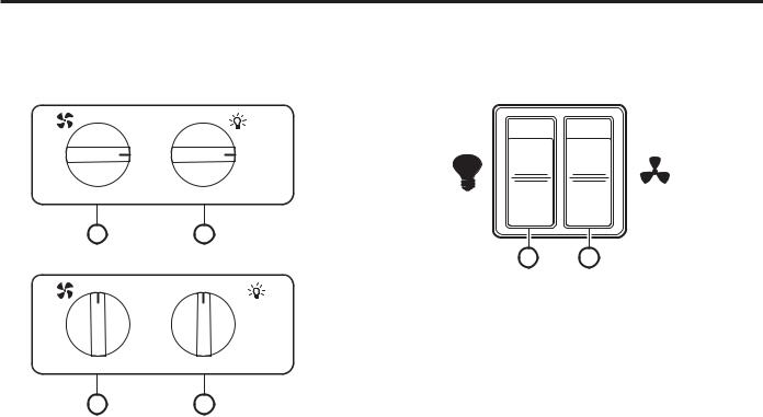
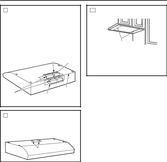
5 REMOVE WIRING COVER
Remove the wiring cover from inside the hood. Set the cover and its mounting screws aside.
Wiring cover
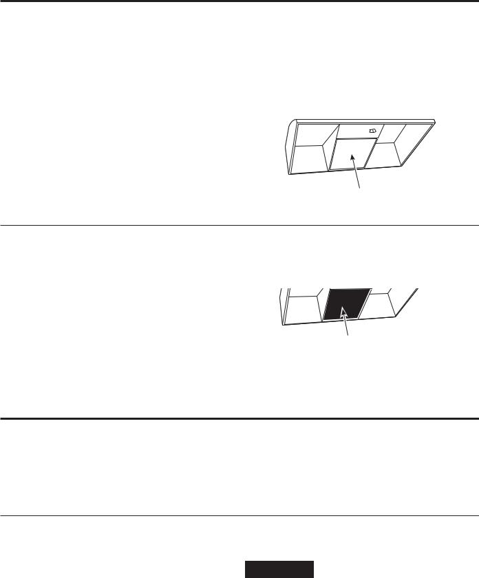
6 REMOVE WIRING KNOCKOUT
Remove either the top or the back wiring knockout as needed and install an approved strain relief clamp.
Top Back knockout knockout
Strain relief |
Strain relief |
clamp |
|
clamp |
|
7 REMOVE DUCT KNOCKOUT
If recirculating, non-vented ductless (JN327, JN328 and RN328, and optional for JV247, JV248, JV347, JV348, JV367 and AV447 models only), skip to Step 11 D and proceed.
Using a flat-blade screwdriver, remove the appropriate duct knockout from the top or back of the hood.
31»4s x 10s Rectangular |
7s Round vertical |
discharge. Remove |
|
vertical discharge. |
circular duct knockout only. |
Remove top rectangular |
|
duct knockout only. |
|
31»4s x 10s Rectangular horizontal discharge. Remove rear rectangular duct knockout only.
<![endif]>INSTRUCTIONS INSTALLATION
11
<![endif]>INSTALLATION INSTRUCTIONS
Installation Instructions
8FOR 3-1-4" X 10" RECTANGULAR DUCTED DISCHARGE INSTALLATIONS
ONLY:
Attach exhaust adaptor/damper over the appropriate knockout opening (for vertical or horizontal, depending on installation) with two exhaust adaptor screws. Make sure damper pivot is nearest to top/back edge of hood. Remove tape from damper flap.
Exhaust adaptor/damper
(vertical discharge position)
Tape
Top/back edge
|
Pivot |
Exhaust adaptor/damper |
|
(depending on |
|
|
installation) |
(horizontal discharge |
|
|
position) |
9 |
FOR 7" ROUND VERTICAL |
|
|
DUCTED DISCHARGE |
|
|
INSTALLATIONS ONLY: |
|
|
Bend up the duct alignment ears in preparation |
|
|
IRU ODWHU DWWDFKPHQW RI WKH Ǝ GXFW |
|
|
|
Attachment ear tabs |
10FOR RECESSED-BOTTOM CABINETS ONLY
Wood shims (minimum thickness 3/8s
If the cabinets have front, side or back trim,
PDNH ZRRG VKLPV D PLQLPXP RI Ǝ WKLFN and cut to fit the width of the inner recessed cabinet bottom. Attach them to the cabinet bottom recess on both sides. See Step 11 for marking locations.
12 |
49-80589-8 |
 Loading...