


 Loading...
GE Healthcare
Dash 3000/4000/5000™ Patient Monitor
Service Manual
Software Version 6.5 or later
AC Battery
Power
Charging Status
A  B
B 
Graph
NBP Go/Stop
Zero All
Trim Knob
Silence Alarm/
Admit
Dash 3000/4000/5000 English
2023909-008 (CD)
2023896-100 (paper)
© 2008, 2009 General Electric Company All Rights Reserved

NOTE: The information in this manual only applies to Dash 3000/4000/5000 patient monitors with software version 6.5 or later. It does not apply to earlier software versions. Due to continuing product innovation, specifications in this manual are subject to change without notice.
NOTE: The assembly drawings in this manual only support patient monitors with the SD0 product code. Patient monitors with the SD0 product code are only compatible with software version 6.5 or later.
NOTE: For technical documentation purposes, the abbreviation GE is used for the legal entity name, GE Medical Systems
Information Technologies.
Listed below are GE Medical Systems Information Technologies trademarks. All other trademarks contained herein are the property of their respective owners.
DASH, DINAMAP, EAGLE, MULTI-LINK, MUSE, SAM, SOLAR, TRIM KNOB, and UNITY NETWORK are trademarks of GE Medical Systems Information Technologies registered in the United States Patent and Trademark Office.
12SL, CENTRALSCOPE, INTELLIRATE, MENTOR, and SUPERSTAT are trademarks of GE Medical Systems Information Technologies.
T-2 |
Dash 3000/4000/5000 |
2000966-456D |
|
|
19 October 2009 |

1
2
Contents
Introduction . . . . . . . . . . . . . . . . . . . . . . . . . . . . . . . . . . . . 1-1
Manual information . . . . . . . . . . . . . . . . . . . . . . . . . . . . . . . . . . . . . . . . . . . . . . . . . . 1-2
Revision history . . . . . . . . . . . . . . . . . . . . . . . . . . . . . . . . . . . . . . . . . . . . . . . . . . . 1-2 Manual purpose . . . . . . . . . . . . . . . . . . . . . . . . . . . . . . . . . . . . . . . . . . . . . . . . . . . 1-2 Intended audience . . . . . . . . . . . . . . . . . . . . . . . . . . . . . . . . . . . . . . . . . . . . . . . . . 1-2 Ordering manuals . . . . . . . . . . . . . . . . . . . . . . . . . . . . . . . . . . . . . . . . . . . . . . . . . 1-2
Safety information . . . . . . . . . . . . . . . . . . . . . . . . . . . . . . . . . . . . . . . . . . . . . . . . . . . 1-3
Responsibility of the manufacturer . . . . . . . . . . . . . . . . . . . . . . . . . . . . . . . . . . . . . 1-3 General . . . . . . . . . . . . . . . . . . . . . . . . . . . . . . . . . . . . . . . . . . . . . . . . . . . . . . . . . 1-3 Warnings, cautions, and notes . . . . . . . . . . . . . . . . . . . . . . . . . . . . . . . . . . . . . . . . 1-4
Equipment symbols . . . . . . . . . . . . . . . . . . . . . . . . . . . . . . . . . . . . . . . . . . . . . . . . . . 1-5
Service information . . . . . . . . . . . . . . . . . . . . . . . . . . . . . . . . . . . . . . . . . . . . . . . . . . 1-8
Service requirements . . . . . . . . . . . . . . . . . . . . . . . . . . . . . . . . . . . . . . . . . . . . . . . 1-8 Equipment identification . . . . . . . . . . . . . . . . . . . . . . . . . . . . . . . . . . . . . . . . . . . . . 1-8
Equipment overview . . . . . . . . . . . . . . . . . . . . . . . . . . . . . 2-1
Components . . . . . . . . . . . . . . . . . . . . . . . . . . . . . . . . . . . . . . . . . . . . . . . . . . . . . . . . 2-2
Monitoring system . . . . . . . . . . . . . . . . . . . . . . . . . . . . . . . . . . . . . . . . . . . . . . . . . 2-2 Patient monitor . . . . . . . . . . . . . . . . . . . . . . . . . . . . . . . . . . . . . . . . . . . . . . . . . . . . 2-2 Controls and indicators . . . . . . . . . . . . . . . . . . . . . . . . . . . . . . . . . . . . . . . . . . . . . 2-5 Exchangeable or compatible battery packs . . . . . . . . . . . . . . . . . . . . . . . . . . . . . . 2-9 Optional components . . . . . . . . . . . . . . . . . . . . . . . . . . . . . . . . . . . . . . . . . . . . . . 2-10 Optional remote control . . . . . . . . . . . . . . . . . . . . . . . . . . . . . . . . . . . . . . . . . . . . 2-13
Software packages and software options . . . . . . . . . . . . . . . . . . . . . . . . . . . . . . . 2-14
Software packages . . . . . . . . . . . . . . . . . . . . . . . . . . . . . . . . . . . . . . . . . . . . . . . 2-14 Software options . . . . . . . . . . . . . . . . . . . . . . . . . . . . . . . . . . . . . . . . . . . . . . . . . 2-14
Ethernet communication . . . . . . . . . . . . . . . . . . . . . . . . . . . . . . . . . . . . . . . . . . . . . 2-15
About Ethernet . . . . . . . . . . . . . . . . . . . . . . . . . . . . . . . . . . . . . . . . . . . . . . . . . . . 2-15 Twisted pair . . . . . . . . . . . . . . . . . . . . . . . . . . . . . . . . . . . . . . . . . . . . . . . . . . . . . 2-15 Network Terms . . . . . . . . . . . . . . . . . . . . . . . . . . . . . . . . . . . . . . . . . . . . . . . . . . . 2-16
Theory of operation . . . . . . . . . . . . . . . . . . . . . . . . . . . . . . . . . . . . . . . . . . . . . . . . . 2-17
Components . . . . . . . . . . . . . . . . . . . . . . . . . . . . . . . . . . . . . . . . . . . . . . . . . . . . . 2-17 Overall patient monitor block diagram . . . . . . . . . . . . . . . . . . . . . . . . . . . . . . . . . 2-17 Power supply . . . . . . . . . . . . . . . . . . . . . . . . . . . . . . . . . . . . . . . . . . . . . . . . . . . . 2-18 Data Acquisition System (DAS) . . . . . . . . . . . . . . . . . . . . . . . . . . . . . . . . . . . . . . 2-18
2000966-456D |
Dash 3000/4000/5000 |
i |

3
4
Processor/power management subsystem . . . . . . . . . . . . . . . . . . . . . . . . . . . . . 2-27 Lithium-Ion battery power . . . . . . . . . . . . . . . . . . . . . . . . . . . . . . . . . . . . . . . . . . 2-35 Speaker . . . . . . . . . . . . . . . . . . . . . . . . . . . . . . . . . . . . . . . . . . . . . . . . . . . . . . . . 2-40 Handle subassembly . . . . . . . . . . . . . . . . . . . . . . . . . . . . . . . . . . . . . . . . . . . . . . 2-40 Interfaces . . . . . . . . . . . . . . . . . . . . . . . . . . . . . . . . . . . . . . . . . . . . . . . . . . . . . . . 2-40 Storage and backup . . . . . . . . . . . . . . . . . . . . . . . . . . . . . . . . . . . . . . . . . . . . . . . 2-42 Optional thermal printer . . . . . . . . . . . . . . . . . . . . . . . . . . . . . . . . . . . . . . . . . . . . 2-43
Installation . . . . . . . . . . . . . . . . . . . . . . . . . . . . . . . . . . . . . 3-1
Installation overview . . . . . . . . . . . . . . . . . . . . . . . . . . . . . . . . . . . . . . . . . . . . . . . . . 3-2 Inspection . . . . . . . . . . . . . . . . . . . . . . . . . . . . . . . . . . . . . . . . . . . . . . . . . . . . . . . . . . 3-3 Before you begin... . . . . . . . . . . . . . . . . . . . . . . . . . . . . . . . . . . . . . . . . . . . . . . . . . . 3-4
Connections . . . . . . . . . . . . . . . . . . . . . . . . . . . . . . . . . . . . . . . . . . . . . . . . . . . . . . . . 3-5
Back panel connections . . . . . . . . . . . . . . . . . . . . . . . . . . . . . . . . . . . . . . . . . . . . . 3-5
Power up . . . . . . . . . . . . . . . . . . . . . . . . . . . . . . . . . . . . . . . . . . . . . . . . . . . . . . . . 3-7
Configure . . . . . . . . . . . . . . . . . . . . . . . . . . . . . . . . . . . . . . . . . . . . . . . . . . . . . . . . 3-7
Dash installation checkout procedure . . . . . . . . . . . . . . . . . . . . . . . . . . . . . . . . . . . 3-8
Configuration . . . . . . . . . . . . . . . . . . . . . . . . . . . . . . . . . . . 4-1
Before you begin... . . . . . . . . . . . . . . . . . . . . . . . . . . . . . . . . . . . . . . . . . . . . . . . . . . 4-2
Service menus . . . . . . . . . . . . . . . . . . . . . . . . . . . . . . . . . . . . . . . . . . . . . . . . . . . . . . 4-3
Boot Loader Service Menu . . . . . . . . . . . . . . . . . . . . . . . . . . . . . . . . . . . . . . . . . . 4-4 Main menu service mode . . . . . . . . . . . . . . . . . . . . . . . . . . . . . . . . . . . . . . . . . . . . 4-5
Procedures . . . . . . . . . . . . . . . . . . . . . . . . . . . . . . . . . . . . . . . . . . . . . . . . . . . . . . . . . |
4-9 |
Set print locations . . . . . . . . . . . . . . . . . . . . . . . . . . . . . . . . . . . . . . . . . . . . . . . . . . |
4-10 |
Service Mode settings . . . . . . . . . . . . . . . . . . . . . . . . . . . . . . . . . . . . . . . . . . . . . . . |
4-11 |
Set Unit Name . . . . . . . . . . . . . . . . . . . . . . . . . . . . . . . . . . . . . . . . . . . . . . . . . . . |
4-11 |
Set Bed Number . . . . . . . . . . . . . . . . . . . . . . . . . . . . . . . . . . . . . . . . . . . . . . . . . |
4-11 |
Patient-Monitor Type . . . . . . . . . . . . . . . . . . . . . . . . . . . . . . . . . . . . . . . . . . . . . . |
4-11 |
Admit Menu . . . . . . . . . . . . . . . . . . . . . . . . . . . . . . . . . . . . . . . . . . . . . . . . . . . . . |
4-13 |
Confirm or configure wireless LAN . . . . . . . . . . . . . . . . . . . . . . . . . . . . . . . . . . . |
4-14 |
Boot Code settings . . . . . . . . . . . . . . . . . . . . . . . . . . . . . . . . . . . . . . . . . . . . . . . . . 4-16
Set Defib Sync Voltage and pulse width . . . . . . . . . . . . . . . . . . . . . . . . . . . . . . . 4-16 Set Line Frequency . . . . . . . . . . . . . . . . . . . . . . . . . . . . . . . . . . . . . . . . . . . . . . . 4-16 Set CIC and QS protocol . . . . . . . . . . . . . . . . . . . . . . . . . . . . . . . . . . . . . . . . . . . 4-17 Set MUSE system protocol . . . . . . . . . . . . . . . . . . . . . . . . . . . . . . . . . . . . . . . . . 4-17
ii |
Dash 3000/4000/5000 |
2000966-456D |

Transcutaneous Pace Blank Length . . . . . . . . . . . . . . . . . . . . . . . . . . . . . . . . . . 4-17 Set Country Selection . . . . . . . . . . . . . . . . . . . . . . . . . . . . . . . . . . . . . . . . . . . . . 4-18 Set Language . . . . . . . . . . . . . . . . . . . . . . . . . . . . . . . . . . . . . . . . . . . . . . . . . . . . 4-18 Enable or disable AFIB Identification . . . . . . . . . . . . . . . . . . . . . . . . . . . . . . . . . . 4-19 Enable or disable IntelliRate . . . . . . . . . . . . . . . . . . . . . . . . . . . . . . . . . . . . . . . . 4-19 Analog Out Buzz . . . . . . . . . . . . . . . . . . . . . . . . . . . . . . . . . . . . . . . . . . . . . . . . . 4-20 Completion . . . . . . . . . . . . . . . . . . . . . . . . . . . . . . . . . . . . . . . . . . . . . . . . . . . . . . 4-20
|
Advanced user procedures . . . . . . . . . . . . . . . . . . . . . . . . . . . . . . . . . . . . . . . . . . . |
4-21 |
|
Procedures . . . . . . . . . . . . . . . . . . . . . . . . . . . . . . . . . . . . . . . . . . . . . . . . . . . . . . |
4-21 |
|
Set time and date . . . . . . . . . . . . . . . . . . . . . . . . . . . . . . . . . . . . . . . . . . . . . . . . . |
4-21 |
|
Transfer monitor defaults . . . . . . . . . . . . . . . . . . . . . . . . . . . . . . . . . . . . . . . . . . . |
4-22 |
5 |
Preventive maintenance . . . . . . . . . . . . . . . . . . . . . . . . . . |
5-1 |
|
Maintenance schedule . . . . . . . . . . . . . . . . . . . . . . . . . . . . . . . . . . . . . . . . . . . . . . . . |
5-2 |
|
Visual inspection . . . . . . . . . . . . . . . . . . . . . . . . . . . . . . . . . . . . . . . . . . . . . . . . . . . . |
5-3 |
|
Cleaning and disinfecting the patient monitor . . . . . . . . . . . . . . . . . . . . . . . . . . . . |
5-3 |
|
Procedure . . . . . . . . . . . . . . . . . . . . . . . . . . . . . . . . . . . . . . . . . . . . . . . . . . . . . . |
. 5-3 |
|
Cautions . . . . . . . . . . . . . . . . . . . . . . . . . . . . . . . . . . . . . . . . . . . . . . . . . . . . . . . . |
. 5-4 |
|
Impact or results of improper cleaning products and processes . . . . . . . . . . . . . |
. 5-5 |
|
Cleaning products to avoid . . . . . . . . . . . . . . . . . . . . . . . . . . . . . . . . . . . . . . . . . |
. 5-5 |
|
Storage . . . . . . . . . . . . . . . . . . . . . . . . . . . . . . . . . . . . . . . . . . . . . . . . . . . . . . . . |
. 5-5 |
|
Clean the print head . . . . . . . . . . . . . . . . . . . . . . . . . . . . . . . . . . . . . . . . . . . . . . . |
. 5-6 |
|
Cleaning, disinfecting and storing GE ECG cables and leadwires . . . . . . . . . . . . |
5-7 |
|
Cleaning and disinfecting . . . . . . . . . . . . . . . . . . . . . . . . . . . . . . . . . . . . . . . . . . . |
. 5-7 |
|
Sterilization . . . . . . . . . . . . . . . . . . . . . . . . . . . . . . . . . . . . . . . . . . . . . . . . . . . . . |
. 5-8 |
|
Cautions . . . . . . . . . . . . . . . . . . . . . . . . . . . . . . . . . . . . . . . . . . . . . . . . . . . . . . . . |
. 5-8 |
|
Storage . . . . . . . . . . . . . . . . . . . . . . . . . . . . . . . . . . . . . . . . . . . . . . . . . . . . . . . . |
. 5-8 |
|
Improper cleaning products and processes impact or results . . . . . . . . . . . . . . . |
. 5-8 |
|
Cleaning products to avoid . . . . . . . . . . . . . . . . . . . . . . . . . . . . . . . . . . . . . . . . . |
. 5-9 |
|
Cleaning other applied parts . . . . . . . . . . . . . . . . . . . . . . . . . . . . . . . . . . . . . . . . . . |
5-9 |
|
Battery maintenance . . . . . . . . . . . . . . . . . . . . . . . . . . . . . . . . . . . . . . . . . . . . . . . . |
5-10 |
|
How to charge the battery . . . . . . . . . . . . . . . . . . . . . . . . . . . . . . . . . . . . . . . . . . |
5-10 |
|
How to condition the battery . . . . . . . . . . . . . . . . . . . . . . . . . . . . . . . . . . . . . . . . |
5-10 |
|
How to store the battery . . . . . . . . . . . . . . . . . . . . . . . . . . . . . . . . . . . . . . . . . . . . |
5-12 |
|
How to wake up the battery . . . . . . . . . . . . . . . . . . . . . . . . . . . . . . . . . . . . . . . . . |
5-12 |
|
How to replace the batteries . . . . . . . . . . . . . . . . . . . . . . . . . . . . . . . . . . . . . . . . |
5-14 |
|
Rechargeable battery recycling . . . . . . . . . . . . . . . . . . . . . . . . . . . . . . . . . . . . . . |
5-14 |
|
About the Cadex SMart Two+ charger . . . . . . . . . . . . . . . . . . . . . . . . . . . . . . . . . |
5-15 |
|
Clear the stored patient data memory . . . . . . . . . . . . . . . . . . . . . . . . . . . . . . . . . . |
5-16 |
2000966-456D |
Dash 3000/4000/5000 |
iii |

6
7
Troubleshooting . . . . . . . . . . . . . . . . . . . . . . . . . . . . . . . . |
6-1 |
Fault analysis . . . . . . . . . . . . . . . . . . . . . . . . . . . . . . . . . . . . . . . . . . . . . . . . . . . . . . . 6-2
Overview . . . . . . . . . . . . . . . . . . . . . . . . . . . . . . . . . . . . . . . . . . . . . . . . . . . . . . . . 6-2 Required tools or equipment . . . . . . . . . . . . . . . . . . . . . . . . . . . . . . . . . . . . . . . . . 6-2 Problems . . . . . . . . . . . . . . . . . . . . . . . . . . . . . . . . . . . . . . . . . . . . . . . . . . . . . . . . 6-2 Acquisition PCB symptoms . . . . . . . . . . . . . . . . . . . . . . . . . . . . . . . . . . . . . . . . . . 6-4 Processor PCB symptoms . . . . . . . . . . . . . . . . . . . . . . . . . . . . . . . . . . . . . . . . . . . 6-4
Error messages . . . . . . . . . . . . . . . . . . . . . . . . . . . . . . . . . . . . . . . . . . . . . . . . . . . . . 6-5
Battery alarms and messages . . . . . . . . . . . . . . . . . . . . . . . . . . . . . . . . . . . . . . . . . 6-7
Battery messages displayed in the ECG waveform area . . . . . . . . . . . . . . . . . . . . 6-7 Battery messages displayed in the Battery Status information window . . . . . . . . . 6-8 Battery Messages Displayed in the Battery Fuel Gauge Icon . . . . . . . . . . . . . . . . 6-8
Writer or printer . . . . . . . . . . . . . . . . . . . . . . . . . . . . . . . . . . . . . . . . . . . . . . . . . . . . . 6-9
External . . . . . . . . . . . . . . . . . . . . . . . . . . . . . . . . . . . . . . . . . . . . . . . . . . . . . . . . . 6-9 Internal . . . . . . . . . . . . . . . . . . . . . . . . . . . . . . . . . . . . . . . . . . . . . . . . . . . . . . . . . . 6-9
No waveform at central station . . . . . . . . . . . . . . . . . . . . . . . . . . . . . . . . . . . . . . . |
6-10 |
Monitor defaults transfer . . . . . . . . . . . . . . . . . . . . . . . . . . . . . . . . . . . . . . . . . . . . |
6-11 |
Storing monitor defaults . . . . . . . . . . . . . . . . . . . . . . . . . . . . . . . . . . . . . . . . . . . . |
6-11 |
Copying stored monitor defaults . . . . . . . . . . . . . . . . . . . . . . . . . . . . . . . . . . . . . |
6-11 |
Change internet address . . . . . . . . . . . . . . . . . . . . . . . . . . . . . . . . . . . . . . . . . . . . . 6-12
Review errors . . . . . . . . . . . . . . . . . . . . . . . . . . . . . . . . . . . . . . . . . . . . . . . . . . . . . . 6-13
View output or input errors . . . . . . . . . . . . . . . . . . . . . . . . . . . . . . . . . . . . . . . . . . 6-13 Useful error data . . . . . . . . . . . . . . . . . . . . . . . . . . . . . . . . . . . . . . . . . . . . . . . . . 6-14
Get error logs . . . . . . . . . . . . . . . . . . . . . . . . . . . . . . . . . . . . . . . . . . . . . . . . . . . . . . 6-16
Get logs via PC using netUpdate . . . . . . . . . . . . . . . . . . . . . . . . . . . . . . . . . . . . . 6-16 Get logs via CIC . . . . . . . . . . . . . . . . . . . . . . . . . . . . . . . . . . . . . . . . . . . . . . . . . . 6-21 Get logs via Centralscope . . . . . . . . . . . . . . . . . . . . . . . . . . . . . . . . . . . . . . . . . . 6-21
Wireless LAN . . . . . . . . . . . . . . . . . . . . . . . . . . . . . . . . . . . . . . . . . . . . . . . . . . . . . . 6-24
Access Service Mode . . . . . . . . . . . . . . . . . . . . . . . . . . . . . . . . . . . . . . . . . . . . . 6-24 Identify the wireless technology . . . . . . . . . . . . . . . . . . . . . . . . . . . . . . . . . . . . . . 6-24 802.11b . . . . . . . . . . . . . . . . . . . . . . . . . . . . . . . . . . . . . . . . . . . . . . . . . . . . . . . . 6-26 802.11 . . . . . . . . . . . . . . . . . . . . . . . . . . . . . . . . . . . . . . . . . . . . . . . . . . . . . . . . . 6-29
Field replaceable units . . . . . . . . . . . . . . . . . . . . . . . . . . . 7-1
Ordering field replaceable units . . . . . . . . . . . . . . . . . . . . . . . . . . . . . . . . . . . . . . . . 7-2 Field replaceable units . . . . . . . . . . . . . . . . . . . . . . . . . . . . . . . . . . . . . . . . . . . . . . . 7-3
iv |
Dash 3000/4000/5000 |
2000966-456D |

|
Disassembly guidelines . . . . . . . . . . . . . . . . . . . . . . . . . . . . . . . . . . . . . . . . . . . . . . |
7-7 |
|
Tools required . . . . . . . . . . . . . . . . . . . . . . . . . . . . . . . . . . . . . . . . . . . . . . . . . . . |
. 7-7 |
|
Before disassembly . . . . . . . . . . . . . . . . . . . . . . . . . . . . . . . . . . . . . . . . . . . . . . . |
. 7-7 |
|
Hardware precautions . . . . . . . . . . . . . . . . . . . . . . . . . . . . . . . . . . . . . . . . . . . . . |
. 7-8 |
|
Electrostatic discharge (ESD) precautions . . . . . . . . . . . . . . . . . . . . . . . . . . . . . |
. 7-8 |
|
Remove or replace handle assembly . . . . . . . . . . . . . . . . . . . . . . . . . . . . . . . . . . . . |
7-9 |
|
Remove or replace display assembly . . . . . . . . . . . . . . . . . . . . . . . . . . . . . . . . . . |
7-12 |
|
Replace display flex assembly . . . . . . . . . . . . . . . . . . . . . . . . . . . . . . . . . . . . . . . . |
7-18 |
|
Replace display assembly parts . . . . . . . . . . . . . . . . . . . . . . . . . . . . . . . . . . . . . . . |
7-20 |
|
Open display assembly . . . . . . . . . . . . . . . . . . . . . . . . . . . . . . . . . . . . . . . . . . . . |
7-21 |
|
Replace Dash 4000/5000 alarm light . . . . . . . . . . . . . . . . . . . . . . . . . . . . . . . . . . |
7-22 |
|
Replace display inverter . . . . . . . . . . . . . . . . . . . . . . . . . . . . . . . . . . . . . . . . . . . . |
7-23 |
|
Replace keypad assembly or Trim Knob control . . . . . . . . . . . . . . . . . . . . . . . . . |
7-24 |
|
Replace display components without LCD . . . . . . . . . . . . . . . . . . . . . . . . . . . . . |
7-25 |
|
Replace main unit parts . . . . . . . . . . . . . . . . . . . . . . . . . . . . . . . . . . . . . . . . . . . . . |
7-28 |
|
Replace DAS assembly . . . . . . . . . . . . . . . . . . . . . . . . . . . . . . . . . . . . . . . . . . . . |
7-28 |
|
Replace wireless card . . . . . . . . . . . . . . . . . . . . . . . . . . . . . . . . . . . . . . . . . . . . . |
7-32 |
|
Replace NBP pump assembly . . . . . . . . . . . . . . . . . . . . . . . . . . . . . . . . . . . . . . . |
7-33 |
|
Replace writer assembly or writer flex . . . . . . . . . . . . . . . . . . . . . . . . . . . . . . . . . |
7-34 |
|
Replace speaker assembly . . . . . . . . . . . . . . . . . . . . . . . . . . . . . . . . . . . . . . . . . |
7-35 |
|
Replace CPU/battery housing assembly . . . . . . . . . . . . . . . . . . . . . . . . . . . . . . . |
7-37 |
|
Replace power supply assembly . . . . . . . . . . . . . . . . . . . . . . . . . . . . . . . . . . . . . |
7-40 |
|
Replace battery door . . . . . . . . . . . . . . . . . . . . . . . . . . . . . . . . . . . . . . . . . . . . . . . . |
7-42 |
|
Replace foot . . . . . . . . . . . . . . . . . . . . . . . . . . . . . . . . . . . . . . . . . . . . . . . . . . . . . . . |
7-43 |
|
Replace writer cover . . . . . . . . . . . . . . . . . . . . . . . . . . . . . . . . . . . . . . . . . . . . . . . . |
7-44 |
|
Recommended checkout . . . . . . . . . . . . . . . . . . . . . . . . . . . . . . . . . . . . . . . . . . . . |
7-45 |
8 |
Functional and electrical safety checks . . . . . . . . . . . . . |
8-1 |
|
Overview . . . . . . . . . . . . . . . . . . . . . . . . . . . . . . . . . . . . . . . . . . . . . . . . . . . . . . . . . . . |
8-2 |
|
Manufacturer recommendations . . . . . . . . . . . . . . . . . . . . . . . . . . . . . . . . . . . . . |
. 8-2 |
|
Frequency . . . . . . . . . . . . . . . . . . . . . . . . . . . . . . . . . . . . . . . . . . . . . . . . . . . . . . |
. 8-2 |
|
Test equipment . . . . . . . . . . . . . . . . . . . . . . . . . . . . . . . . . . . . . . . . . . . . . . . . . . |
. 8-2 |
|
Functional Checkout procedures . . . . . . . . . . . . . . . . . . . . . . . . . . . . . . . . . . . . . |
. 8-3 |
|
Electrical safety tests . . . . . . . . . . . . . . . . . . . . . . . . . . . . . . . . . . . . . . . . . . . . . . . . |
8-4 |
|
General . . . . . . . . . . . . . . . . . . . . . . . . . . . . . . . . . . . . . . . . . . . . . . . . . . . . . . . . |
. 8-4 |
|
Recommendations . . . . . . . . . . . . . . . . . . . . . . . . . . . . . . . . . . . . . . . . . . . . . . . . |
. 8-4 |
|
Power outlet test . . . . . . . . . . . . . . . . . . . . . . . . . . . . . . . . . . . . . . . . . . . . . . . . . |
. 8-5 |
|
Power cord and plug . . . . . . . . . . . . . . . . . . . . . . . . . . . . . . . . . . . . . . . . . . . . . . |
. 8-5 |
|
Ground (earth) integrity . . . . . . . . . . . . . . . . . . . . . . . . . . . . . . . . . . . . . . . . . . . . |
. 8-6 |
2000966-456D |
Dash 3000/4000/5000 |
v |

Ground (earth) wire leakage current tests . . . . . . . . . . . . . . . . . . . . . . . . . . . . . . . 8-8 Enclosure (Touch) leakage current test . . . . . . . . . . . . . . . . . . . . . . . . . . . . . . . . . 8-9 Patient (source) leakage current test . . . . . . . . . . . . . . . . . . . . . . . . . . . . . . . . . . 8-12 Patient (sink) leakage current test (mains voltage on the applied part) . . . . . . . . 8-14
BISx (option) current leakage tests . . . . . . . . . . . . . . . . . . . . . . . . . . . . . . . . . . . . 8-16
BISx patient (source) leakage current test . . . . . . . . . . . . . . . . . . . . . . . . . . . . . . 8-16 BISx patient (sink) leakage current test . . . . . . . . . . . . . . . . . . . . . . . . . . . . . . . . 8-18 Test completion . . . . . . . . . . . . . . . . . . . . . . . . . . . . . . . . . . . . . . . . . . . . . . . . . . 8-19
Functional Checkout procedures . . . . . . . . . . . . . . . . . . . . . . . . . . . . . . . . . . . . . . 8-20
Frequency . . . . . . . . . . . . . . . . . . . . . . . . . . . . . . . . . . . . . . . . . . . . . . . . . . . . . . 8-20 Identify enabled patient parameters and software options . . . . . . . . . . . . . . . . . 8-20 Patient monitor power-up tests . . . . . . . . . . . . . . . . . . . . . . . . . . . . . . . . . . . . . . 8-21 ECG tests . . . . . . . . . . . . . . . . . . . . . . . . . . . . . . . . . . . . . . . . . . . . . . . . . . . . . . . 8-22 Respiration tests . . . . . . . . . . . . . . . . . . . . . . . . . . . . . . . . . . . . . . . . . . . . . . . . . 8-25 Temperature tests . . . . . . . . . . . . . . . . . . . . . . . . . . . . . . . . . . . . . . . . . . . . . . . . 8-26 Cardiac output tests (option) . . . . . . . . . . . . . . . . . . . . . . . . . . . . . . . . . . . . . . . . 8-27 Invasive blood pressure tests (option) . . . . . . . . . . . . . . . . . . . . . . . . . . . . . . . . . 8-27 Pulse oximetry tests for GE Ohmeda SPO2 oximeter . . . . . . . . . . . . . . . . . . . . . 8-31 Pulse oximetry tests for Masimo SET SPO2 . . . . . . . . . . . . . . . . . . . . . . . . . . . . 8-33 Pulse oximetry tests for Nellcor OxiMax SPO2 . . . . . . . . . . . . . . . . . . . . . . . . . . 8-35 Noninvasive blood pressure tests . . . . . . . . . . . . . . . . . . . . . . . . . . . . . . . . . . . . 8-37 NBP calibration . . . . . . . . . . . . . . . . . . . . . . . . . . . . . . . . . . . . . . . . . . . . . . . . . . 8-39 Analog output and defibrillator synchronization tests . . . . . . . . . . . . . . . . . . . . . . 8-42 End-tidal CO2 test (option) . . . . . . . . . . . . . . . . . . . . . . . . . . . . . . . . . . . . . . . . . . 8-46 Battery tests . . . . . . . . . . . . . . . . . . . . . . . . . . . . . . . . . . . . . . . . . . . . . . . . . . . . . 8-46 Graph or print tests (option) . . . . . . . . . . . . . . . . . . . . . . . . . . . . . . . . . . . . . . . . . 8-46 Display test . . . . . . . . . . . . . . . . . . . . . . . . . . . . . . . . . . . . . . . . . . . . . . . . . . . . . 8-47 Speaker test . . . . . . . . . . . . . . . . . . . . . . . . . . . . . . . . . . . . . . . . . . . . . . . . . . . . . 8-47 Network test (option) . . . . . . . . . . . . . . . . . . . . . . . . . . . . . . . . . . . . . . . . . . . . . . 8-48 Remote control test (option) . . . . . . . . . . . . . . . . . . . . . . . . . . . . . . . . . . . . . . . . . 8-48 BISx test (option) . . . . . . . . . . . . . . . . . . . . . . . . . . . . . . . . . . . . . . . . . . . . . . . . . 8-49 Wireless LAN test (option) . . . . . . . . . . . . . . . . . . . . . . . . . . . . . . . . . . . . . . . . . . 8-51 Dash Port 2 docking station test (option) . . . . . . . . . . . . . . . . . . . . . . . . . . . . . . . 8-53 TRAM-rac 2A module housing peripheral device test (option) . . . . . . . . . . . . . . 8-53 ICG Module test (option) . . . . . . . . . . . . . . . . . . . . . . . . . . . . . . . . . . . . . . . . . . . 8-53
Checkout procedures completion . . . . . . . . . . . . . . . . . . . . . . . . . . . . . . . . . . . . . |
8-54 |
A Electromagnetic compatibility (EMC) . . . . . . . . . . . . . . . . . |
A-1 |
Electromagnetic Compatibility (EMC) . . . . . . . . . . . . . . . . . . . . . . . . . . . . . . . . . . . A-2
Guidance and Manufacturer’s Declaration – Electromagnetic Emissions . . . . . . .A-2 Guidance and manufacturer’s declaration – electromagnetic immunity . . . . . . . .A-3 Guidance and Manufacturer’s Declaration – Electromagnetic Immunity . . . . . . . .A-4 Recommended separation distances . . . . . . . . . . . . . . . . . . . . . . . . . . . . . . . . . . .A-5 Compliant cables and accessories . . . . . . . . . . . . . . . . . . . . . . . . . . . . . . . . . . . .A-6
vi |
Dash 3000/4000/5000 |
2000966-456D |

B Network troubleshooting . . . . . . . . . . . . . . . . . . . . . . . . . . .B-1
Network traffic . . . . . . . . . . . . . . . . . . . . . . . . . . . . . . . . . . . . . . . . . . . . . . . . . . . . . . B-2
Traffic types . . . . . . . . . . . . . . . . . . . . . . . . . . . . . . . . . . . . . . . . . . . . . . . . . . . . . .B-2 Flow . . . . . . . . . . . . . . . . . . . . . . . . . . . . . . . . . . . . . . . . . . . . . . . . . . . . . . . . . . . .B-2
Problem: No waveforms or parameters are displayed at the CIC Pro center . . . B-3
C Checklist . . . . . . . . . . . . . . . . . . . . . . . . . . . . . . . . . . . . . . . .C-1
Checklist . . . . . . . . . . . . . . . . . . . . . . . . . . . . . . . . . . . . . . . . . . . . . . . . . . . . . . . . . . . C-2
2000966-456D |
Dash 3000/4000/5000 |
vii |

viii |
Dash 3000/4000/5000 |
2000966-456D |
1 Introduction
2000966-456D |
Dash 3000/4000/5000 |
1-1 |

Introduction: Manual information
Manual information
Revision history
Each page of this manual has the document part number and revision letter at the bottom of the page. The revision letter identifies the document’s update level. The
revision history of this document is summarized below.
Revision |
Comment |
|
|
A |
Initial release of this manual. |
|
|
B |
Updated electrical safety tests and software release content. |
|
|
C |
Updated Appendix B. |
|
|
D |
Added Appendix for network troubleshooting. |
|
|
Manual purpose
This manual supplies technical information for service representatives and technical personnel so they can maintain the equipment to the assembly level. Use it as a guide for maintenance and electrical repairs considered field repairable. Where necessary the manual identifies additional sources of relevant information and technical assistance.
See the operator’s manual for the instructions necessary to operate the equipment safely in accordance with its function and intended use.
Intended audience
This manual is intended for service representatives and technical personnel who maintain, troubleshoot, or repair this equipment.
Ordering manuals
A paper copy of this manual will be provided upon request. Contact your local GE representative and request the part number on the first page of the manual.
1-2 |
Dash 3000/4000/5000 |
2000966-456D |

Introduction: Safety information
Safety information
Responsibility of the manufacturer
GE is responsible for the effects of safety, reliability, and performance only if:
Assembly operations, extensions, readjustments, modifications, or repairs are carried out by persons authorized by GE.
The electrical installation of the relevant room complies with the requirements of the appropriate regulations.
The equipment is used in accordance with the instructions for use.
General
This device is intended for use under the direct supervision of a licensed health care practitioner.
This device is not intended for home use.
Federal law restricts this device to be sold by or on the order of a physician.
Contact GE for information before connecting any devices to the equipment that are not recommended in this manual.
Parts and accessories used must meet the requirements of the applicable IEC 60601 series safety standards, and/or the system configuration must meet the requirements of the IEC 60601-1-1 medical electrical systems standard.
Periodically, and whenever the integrity of the device is in doubt, test all functions.
The use of accessory equipment not complying with the equivalent safety requirements of this equipment may lead to a reduced level of safety of the resulting system. Consideration relating to the choice shall include:
use of the accessory in the patient vicinity; and
evidence that the safety certification of the accessory has been performed in accordance to the appropriate IEC 60601-1 and/or IEC 60601-1-1 harmonized national standard.
If the installation of the equipment, in the USA, will use 240V rather than 120V, the source must be a center-tapped, 240V, single-phase circuit.
2000966-456D |
Dash 3000/4000/5000 |
1-3 |

Introduction: Safety information
Warnings, cautions, and notes
The terms danger, warning, and caution are used throughout this manual to point out hazards and to designate a degree or level or seriousness. Familiarize yourself with their definitions and significance.
Hazard is defined as a source of potential injury to a person.
DANGER indicates an imminent hazard which, if not avoided, will result in death or serious injury.
WARNING indicates a potential hazard or unsafe practice which, if not avoided, could result in death or serious injury.
CAUTION indicates a potential hazard or unsafe practice which, if not avoided, could result in minor personal injury or product/property damage.
NOTE provides application tips or other useful information to assure that you get the most from your equipment.
1-4 |
Dash 3000/4000/5000 |
2000966-456D |
Introduction: Equipment symbols
Equipment symbols
NOTE: Some symbols may not appear on all equipment.
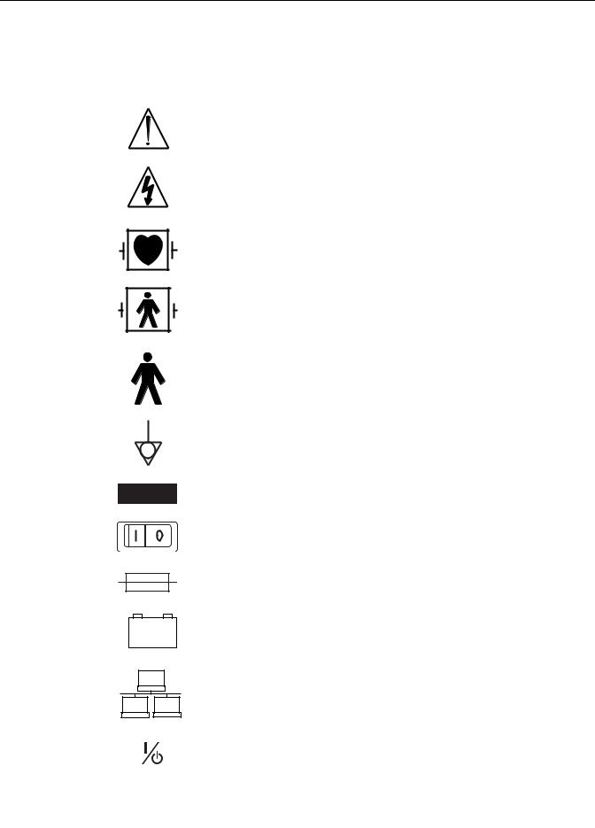
ATTENTION: Consult accompanying documents before using the equipment.
In Europe, this symbol means dangerous or high voltage. In the United States, this symbol represents the caution notice below:
To reduce the risk of electric shock, do not remove cover (or back). Refer servicing to qualified personnel.
Defibrillator-proof type CF equipment; type CF equipment is specifically designed for applications where a conductive connection directly to the heart is established. The paddles indicate the equipment is defibrillator proof.
Defibrillator-proof type BF equipment; type BF equipment is suitable for intentional external and internal application to the patient, excluding direct cardiac application. Type BF equipment is type B equipment with an F-type isolated (floating) part. The paddles indicate the equipment is defibrillator proof.
Type B equipment; type B equipment is suitable for intentional external and internal application to the patient, excluding direct cardiac application.
Equipotential Stud: A ground wire from another device can be tied here to ensure the devices share a common reference.
Alternating current (AC)
Power; I = ON; O= OFF
Fuse
Battery
Indicates the Ethernet connection for the patient monitor.
POWER (Dash 3000/4000)
2000966-456D |
Dash 3000/4000/5000 |
1-5 |
Introduction: Equipment symbols
4P41
2005-08
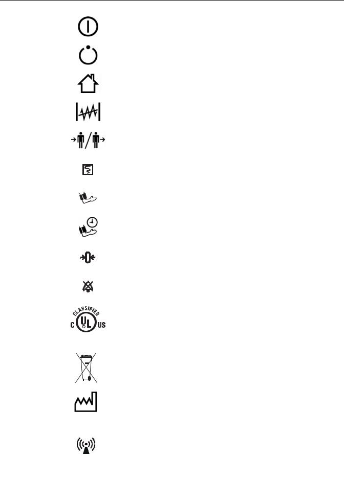
Power (Dash 5000)
Standby (Dash 5000)
Main Display (Dash 5000)
Trend (Dash 5000)
Admit/Discharge (Dash 5000)
Print (Graph Go/Stop on older Dash 3000/4000)
NBP Go/Stop (on older Dash 3000/4000)
NBP Auto (Dash 5000)
Zero All
Silence Alarm/Admit
Medical Equipment
With respect to electric shock, fire and mechanical hazards only in accordance with UL 60601-1, CAN/CSA C22.2 NO. 601, IEC 60601-1, IEC 60601-2-27, IEC 60601-2-30, IEC 60601-2-34, and IEC 60601-2-49.
This symbol indicates that the waste of electrical and electronic equipment must not be disposed as unsorted municipal waste and must be collected separately. Please contact an authorized representative of the manufacturer for information concerning the decommissioning of your equipment.
This symbol indicates the date of manufacture of this device. The first four digits identify the year and the last two digits identify the month.
Non-ionizing electromagnetic radiation: To indicate elevated, potentially dangerous, levels of non-ionizing radiation. Note - In case of application in a warning sign the rules according to ISO 3864-1 shall be adhered to.
IEC 60878 note: See safety sign ISO 7010 - W005 “Warning, non-ionizing radiation”.
1-6 |
Dash 3000/4000/5000 |
2000966-456D |
Introduction: Equipment symbols
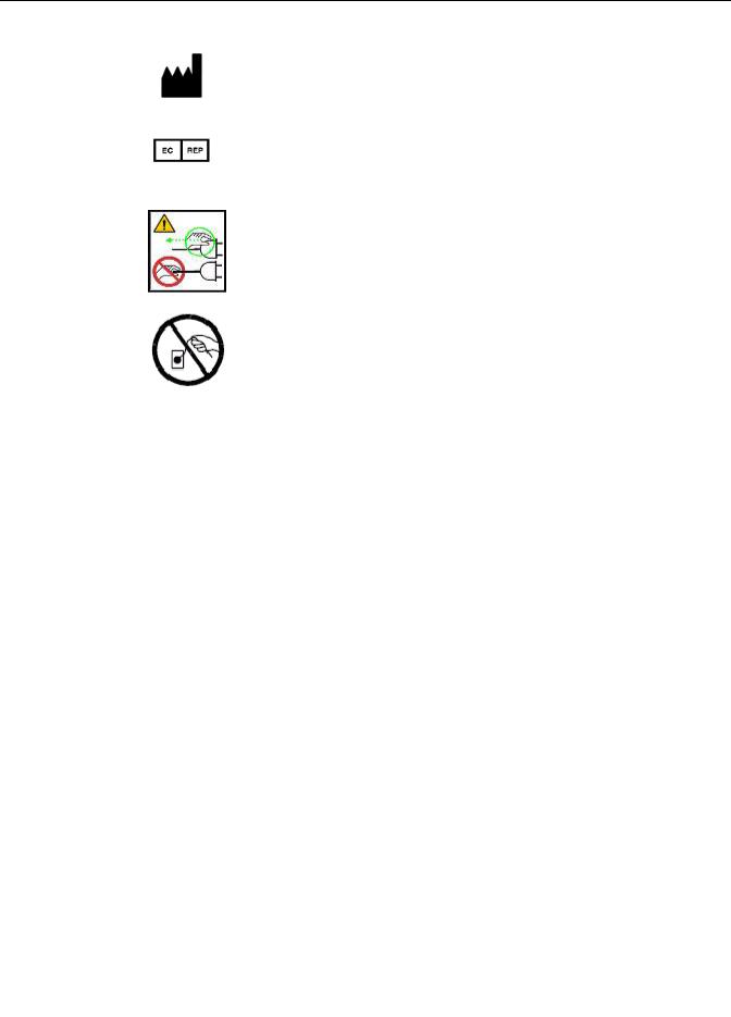
Manufacturer name and address.
European authorized representative.
CAUTION — Safety ground precaution. Remove power cord from the mains source by grasping the plug. Do not pull on the cable.
2000966-456D |
Dash 3000/4000/5000 |
1-7 |
Introduction: Service information
Service information
Service requirements
Follow the service requirements listed below.
Refer equipment servicing to GE-authorized service personnel only.
Any unauthorized attempt to repair equipment under warranty voids that warranty.
It is the user’s responsibility to report the need for service to GE or to one of their authorized agents.
Failure on the part of the responsible individual, hospital, or institution using this equipment to implement a satisfactory maintenance schedule may cause undue equipment failure and possible health hazards.
Regular maintenance, irrespective of usage, is essential to ensure that the equipment will always be functional when required.
Equipment identification
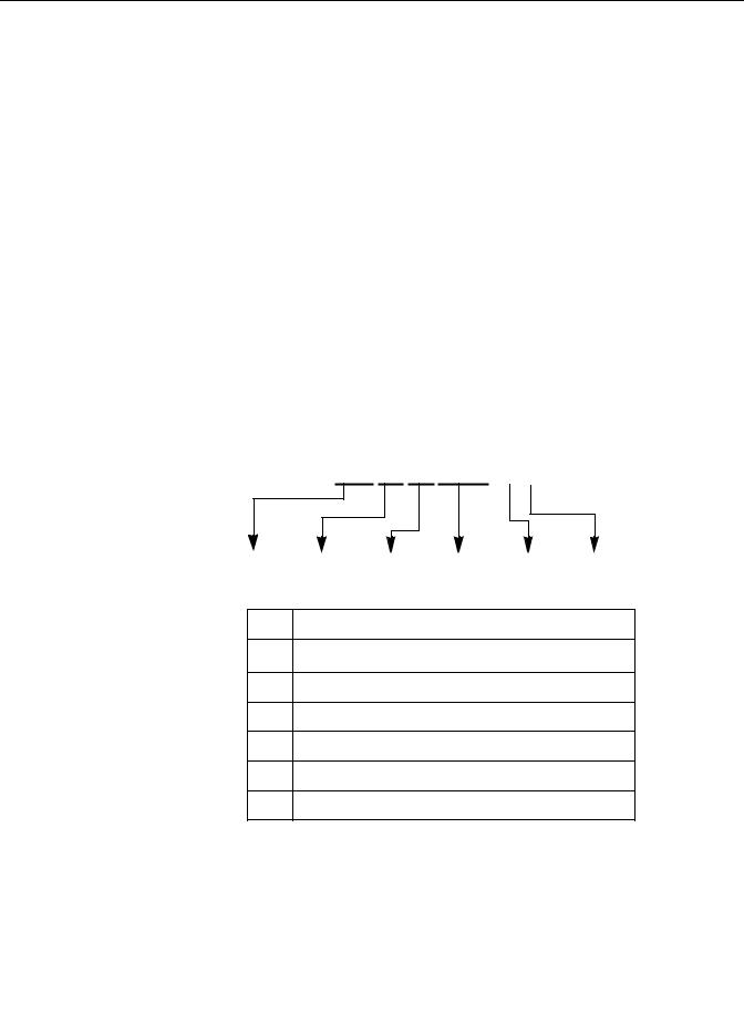
Every GE device has a unique serial number for identification. A sample of the information found on a serial number label is shown below.
### ## ## #### # #
A B C D E F
Description
Aproduct code1
Byear manufactured
Cfiscal week manufactured
Dproduction sequence number
Emanufacturing site
Fmiscellaneous characteristic
1.The current Dash patient monitor product code is SD0.
NOTE
Dash 3000/4000/5000 patient monitors with the SD0 product code are only compatible with software version 6.5 or later.
1-8 |
Dash 3000/4000/5000 |
2000966-456D |

2 Equipment overview
2000966-456D |
Dash 3000/4000/5000 |
2-1 |
Equipment overview: Components
Components
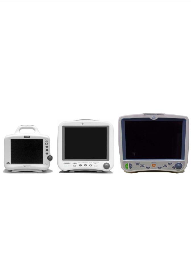
Monitoring system
The Dash patient monitor can function as a portable monitoring device with a builtin writer, or as a flexible care monitoring device connected to the optional Unity Network™ via Ethernet. If using the wireless card or Ethernet connection, optional components are a Clinical Information Center (CIC Pro™) and a Centralscope™ central station.
Patient monitor
This device is designed to monitor a fixed set of parameters including ECG, noninvasive blood pressure, impedance respiration, SpO2, and temperature. Invasive pressure, BISx, and EtCO2 are optional features. Additional specialized features include cardiac output, cardiac calculations, pulmonary calculations, dose calculations, PA wedge (PA wedge is only available with the invasive pressure option), ICG module interface, and SAM™ module interface.
AC Battery
Power
Charging Status
Graph
NBP Go/Stop
Zero All
Trim Knob
Silence Alarm/
Admit
001C 051D 003A
Dash 3000 monitor Dash 4000 monitor Dash 5000 monitor
NOTE
For compatibility information, contact Technical Support.
2-2 |
Dash 3000/4000/5000 |
2000966-456D |
Equipment overview: Components
Right side view
All of the patient cable connectors are located on the right side of the patient monitor. A Trim Knob™ control provides single control operation of virtually all patient monitor functions.
Patient cable
 connectors
002A
Left side view
On the left of the patient monitor, you can find the built-in writer and the battery compartment.
A
B
925B
2000966-456D |
Dash 3000/4000/5000 |
2-3 |
Equipment overview: Components
|
Name |
Description |
|
|
|
|
|
A |
Built-in writer |
The built-in, 4 channel writer is located in the |
|
(optional) |
center of the left side of the monitor. |
||
|
|||
|
|
|
|
B |
Battery compartment |
The battery packs are located in this compartment. |
|
|
The battery compartment may be a single plastic |
||
|
|
door or two silicone doors. |
|
|
|
|
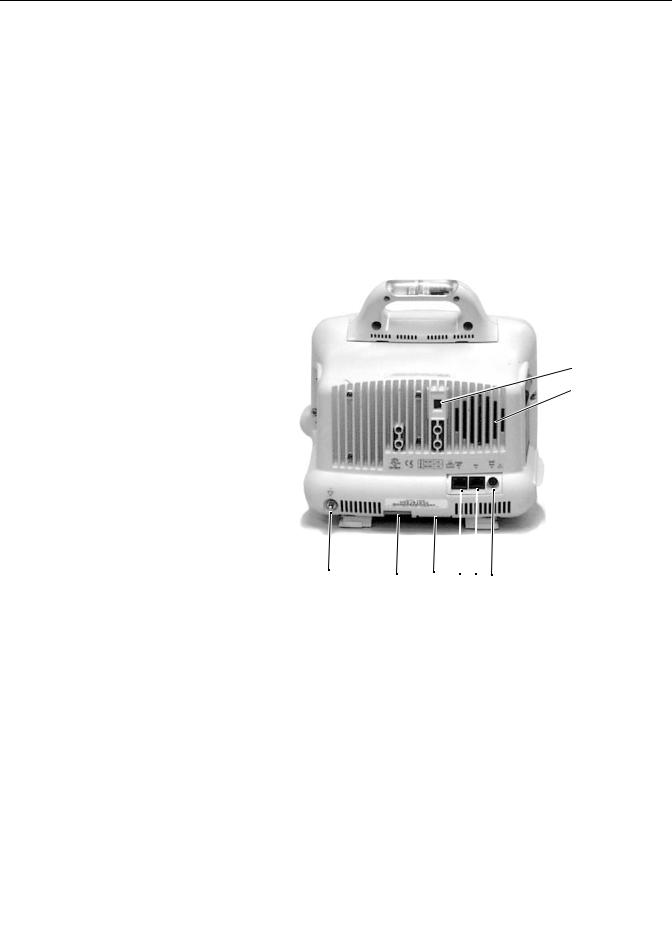
Back view
All ports for equipment and network are on the back of the patient monitor.
A
 B
B
004A
H G F E D C
|
Name |
Description |
|
|
|
A |
line voltage selector |
This selector is factory set to match the line voltage |
|
rating for your country. |
|
|
|
|
|
|
|
B |
audible alarm enunciator |
The internal speaker provides sound for audible alarms. |
|
For better sound quality do not block speaker. |
|
|
|
|
|
|
|
|
Defib Sync port |
Provides ECG analog output signals to user-supplied |
C |
|
equipment. A 5-volt, 2-millisecond artificial pacer spike |
|
is added to the analog output when PACE is on and |
|
|
|
|
|
|
detection occurs. |
|
|
|
D |
Aux port |
Used for TRAM-rac 2A, BISx and other compatible |
|
auxiliary devices. |
|
|
|
|
|
|
|
E |
Ethernet port |
Used to connect a monitor to the Unity Network for |
|
patient monitoring or for software installation. |
|
|
|
|
|
|
|
2-4 |
Dash 3000/4000/5000 |
2000966-456D |
Equipment overview: Components
|
Name |
Description |
|
|
|
|
|
F |
peripheral expansion |
Used for connecting to a Dash™ Port docking station or |
|
port |
other compatible auxiliary devices. |
||
|
|||
|
|
|
|
G |
AC power |
Used for connecting an AC power cable. |
|
|
|
|
|
|
equipotential terminal |
For measurements in or near the heart we recommend |
|
H |
|
connecting the monitor to the potential equalization |
|
|
system. Use the green and yellow potential equalization |
||
|
|
||
|
|
cable and connect it to this pin. |
|
|
|
|
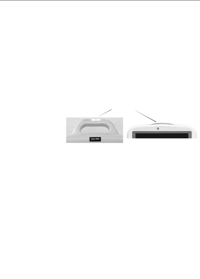
Optional alarm light indicator
An optional alarm light indicator may be built into the handle of the Dash 3000 patient monitor or into the display bezel of the Dash 4000/5000 patient monitor. When activated, the LED indicator flashes red for Crisis patient status alarms and yellow for Warning patient status and system alarms.
Alarm light indicator
536A |
052B |
Dash 3000 monitor |
Dash 4000 and Dash 5000 monitors |
Controls and indicators
The user interface consists of a flat panel display and the keypad assembly that includes a Trim Knob control, function keys, and LED indicators.
Flat panel display
The active-matrix color liquid crystal display (LCD) is assembled into a shock absorbing isolator that fits within the patient monitor’s front bezel to protect the display from mechanical shock during use.
The acrylic optical filter protects the display panel from impact and enhances visibility with its non-glare surface coating on the viewing side of the filter. It also has a scratch-resistance surface coating.
Trim Knob control
The Trim Knob control is a 24-position rotary control with a push selection switch.
2000966-456D |
Dash 3000/4000/5000 |
2-5 |

Equipment overview: Components
Function or power keys
Dash 3000/4000 patient monitors
Power, Print, NBP Go/Stop, Zero All, Silence Alarm/Admit.
Dash 5000 patient monitor
Power, Standby, Admit/Discharge, NBP Go/Stop, NBP Auto, Print, Silence
Alarm, Zero All, Trend, Main Display.
Power key
The patient monitor is powered at all times when it is plugged into AC power. When the patient monitor is not plugged in to AC power, press this key to turn on and turn off the patient monitor.
When AC power is present, this key toggles the operational mode of the patient monitor between normal operation and stand-by mode. In standby mode patient monitoring discontinues. Only the charging function continues and the charging status indicators operate as described below.
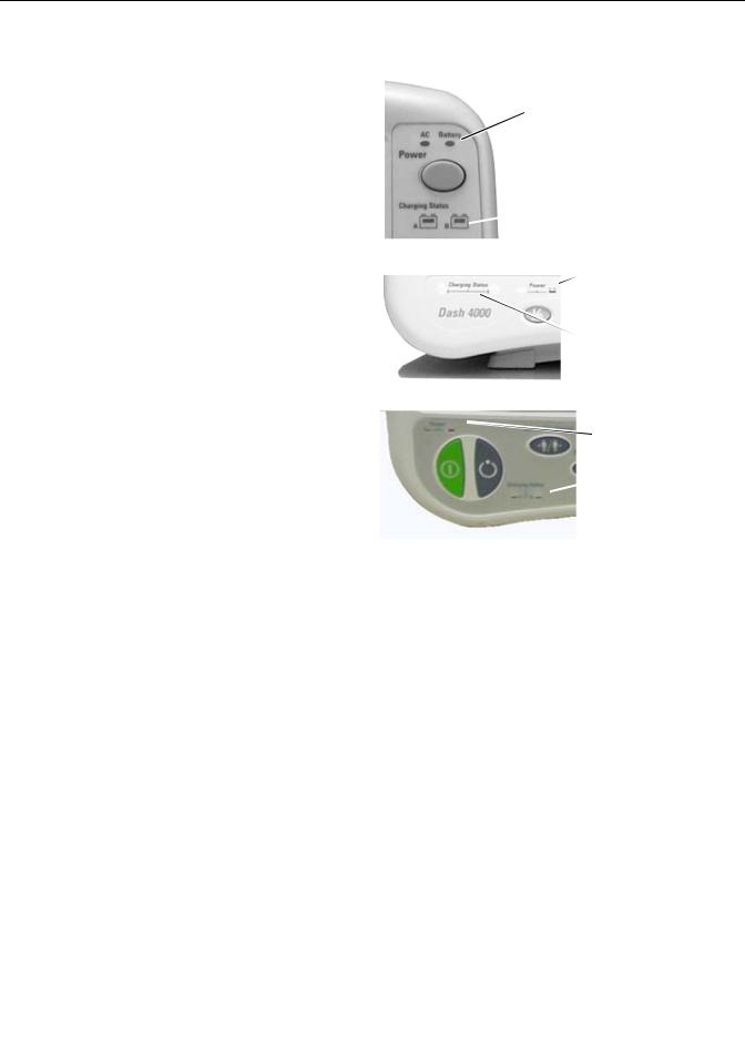
Indicators
While the patient monitor powers up or changes between normal mode and standby mode, all four front panel indicators illuminate.
AC power indicator
The indicator lights green when AC mains power is applied to the patient monitor (including when the patient monitor is in the standby mode). The indicator does not illuminate when the patient monitor has no AC mains power.
Battery power indicator
The indicator lights yellow when the patient monitor is operating on battery power.
The indicator does not illuminate when the patient monitor has no battery power.
2-6 |
Dash 3000/4000/5000 |
2000966-456D |
Equipment overview: Components
Battery indicators are located on the front panel of the patient monitor. They indicate when battery power is used and the battery charging status.
Battery power indicators
Dash 3000
Charge status indicators
009A
Battery power indicators
Dash 4000 |
Charge status |
|
indicators |
053A
Battery power indicators
Dash 5000 |
Charge status |
indicators |
868A
Charging status indicators
An icon for each battery indicates its charging status. The battery icon lights yellow when the respective battery is being charged. If both batteries are present and require charging, then both icons illuminate even though they will be charged sequentially. The battery icon lights green when the respective battery is fully charged.
When the patient monitor is operating under battery power the battery icons are not illuminated. The icons are also not illuminated when the respective battery is either not being charged, not installed, or has failed.
The following table explains what the charging status indicators mean.
NOTE
No specific indicator distinguishes a failed battery pack condition from a condition where the battery is not installed or is not being charged. Go to the Service Menu for Battery Status. Refer to “Battery alarms and messages” on
2000966-456D |
Dash 3000/4000/5000 |
2-7 |

Equipment overview: Components
page 6-7 for further information.
LED color |
Explanation |
|
|
Yellow |
Two battery icons, labeled Charging Status A and B, illuminate yellow |
|
when the respective battery is being charged. If both batteries are present |
|
and require charging, then both icons illuminate yellow even though they |
|
charge sequentially. |
|
|
Green |
The icon lights green when the respective battery is fully charged. |
|
|
No light |
The icon does not illuminate under the following conditions: |
|
The respective battery is not installed. |
|
The patient monitor is operating on battery power. |
|
A failure condition has been detected for the respective battery. |
|
|
Battery status indicators
The battery status indicators are located inside the battery compartment. One green LED indicator is located above each of the two battery slots and lights green when the patient monitor is receiving power solely from the respective battery. The indicators do not illuminate when the patient monitor is not battery powered.
Neither indicator lights when the patient monitor is operating from both batteries simultaneously (e.g., in a very low battery charge condition when both batteries are joined together in order to sustain operation of the patient monitor).
2-8 |
Dash 3000/4000/5000 |
2000966-456D |
Equipment overview: Components
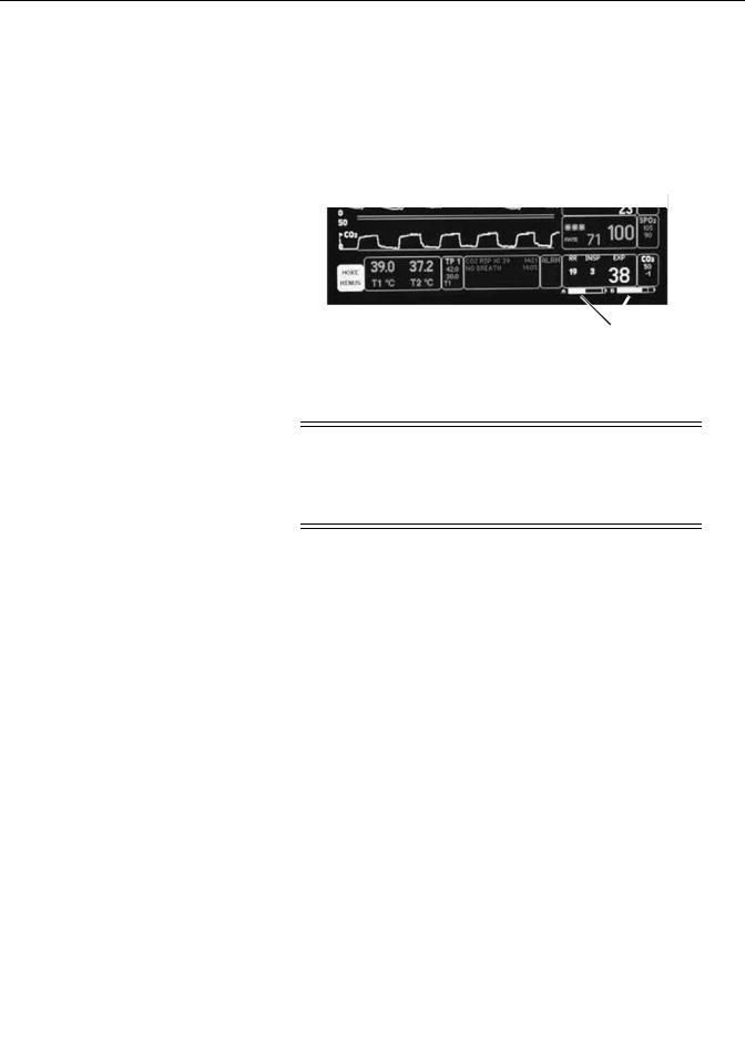
Battery capacity gauge
On-screen capacity gauges indicate the battery's current state of health and charge status. A battery capacity gauge for each battery present displays below the parameter blocks in the lower right corner of the display. The capacity gauge indicates the remaining charge capacity (usable energy left) for each battery.
The capacity gauges fill in from left to right proportional to the battery charge level. The solid portion represents the full charge capacity of the battery as a percentage of its design capacity.
809A
Battery capacity gauges
Exchangeable or compatible battery packs
WARNING
EXPLOSION OR FIRE - Using non-recommended batteries could result in injury/burns to patients and users. Only use batteries recommended or manufactured by GE. The warranty can be voided if non-recommended batteries are used.
Dash patient monitors running software versions 5.4 or later only recognize and charge GE recommended batteries. Non-recommended batteries will run, but not charge, the Dash patient monitor. If battery is labeled GE Approved, the battery is compatible.
NOTE
Incompatible batteries display an “ERROR” message in the Battery Capacity
Gauge on the bottom right corner of the patient monitor screen.
Verify compatibility of an unmarked battery as follows.
1.Install a battery pack in the patient monitor.
2.Using the Trim Knob control, access the Service Mode menu starting from the Main Menu. Select MORE MENUS > MONITOR SETUP > SERVICE MODE.
3.Enter password using the Trim Knob control to select the day and month from patient monitor screen with leading zeros. (e.g. July 4 = 0407).
4.Select BATTERY SERVICE.
5.Verify that the MANUFACTURER NAME does not display INCOMPAT, NME, or UNKNOWN for the battery corresponding to BATTERY A or
BATTERY B slot.
2000966-456D |
Dash 3000/4000/5000 |
2-9 |
Equipment overview: Components
Optional components
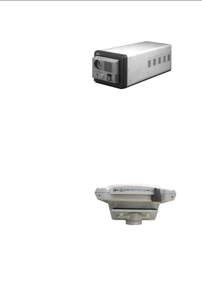
TRAM-rac 2A module housing
The TRAM-rac 2A module housing currently supports the SAM and ICG modules.
797B
An integral power supply is used to run the TRAM-rac 2A and support the needed voltages.
Dash Port 2 docking station
The docking station is a quick mount/dismount base for a Dash patient monitor. It gives the patient monitor easy connect or disconnect access to AC power, Unity Network™, a remote display, and auxiliary devices.
See the Dash Port 2 Docking Station Operating Instructions and the Dash Port 2
Docking Station Service Manual for additional information.
NOTE
When a Dash patient monitor is connected to the docking station, only the docking station’s Ethernet port is active. The Dash patient monitor’s network port remains inactive until the patient monitor is disconnected from the docking station.
823B
An optional remote display can be connected to the system for viewing on a larger monitor, or in a separate room. The remote display requires:
Dash Port 2 docking station,
Dash 3000/4000 patient monitor software version 5 or later, or
Dash patient monitor software version 6 with Dash Port 2 software version 2.0, and
Must be within 150 feet of the Dash patient monitor.
2-10 |
Dash 3000/4000/5000 |
2000966-456D |

Equipment overview: Components
ICG module
The ICG module (impedance cardiography) measures and processes patient hemodynamic data.
825A
BISx
Available in software version 6 or later, BISx measures the effect of anesthetics and sedatives on the brain.
935A
2000966-456D |
Dash 3000/4000/5000 |
2-11 |
Equipment overview: Components
Wireless connection
The flexibility of the optional GE Unity Network is increased by using the wireless network. The wireless connection allows the user to roam from one access point to another, maintaining a strong seamless connection to the Unity Network. GE offers 802.11 and 802.11b wireless options.
The patient monitor, with its optional built-in wireless card, functionally performs the same as a patient monitor connected directly to the optional Unity Network. It can be viewed at the central station and by other GE monitors on the network (e.g., Dash 3000/4000/5000, Eagle™ 4000, and Solar™ patient monitors). Patient monitors with a wireless connection can send and receive patient data via the access points to the Unity Network.
NOTE
It is recommended that wireless patient monitors that are moved from room to room have their patient monitor type configured as Rover or Rover/Combo monitoring.
To extend the Unity Network to a hospital’s 802.11b wireless network, a proper installation and configuration needs to be performed. To maintain continuous wireless patient monitoring, refer to the wireless LAN Configuration Guide and contact GE for consultation in integrating the Unity Network to a 802.11b wireless network.
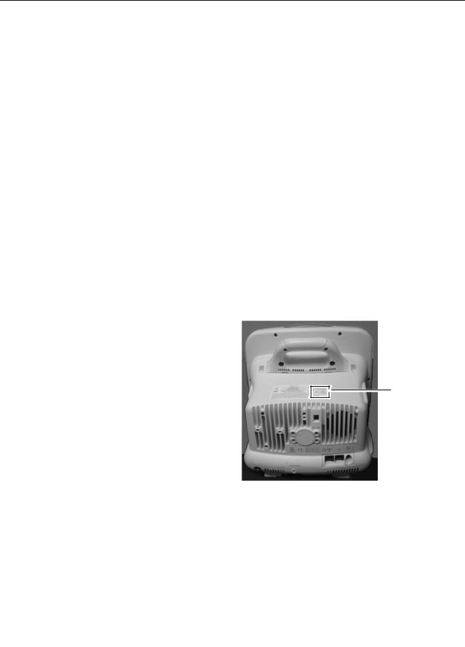
To identify a patient monitor with the wireless option, look for the wireless LAN label.
Wireless
LAN label
940A
2-12 |
Dash 3000/4000/5000 |
2000966-456D |
Loading...