


GE AEM25, AEM18, AEW25, AEW18, AEH25 User Manual 2
...Air Conditioners
Room
ge.com
Safety Instructions . . . . . . . . . . .2, 3
Operating Instructions
Additional Controls . . . . . . . . . . . . .7
Control Knob Models . . . . . . . . . . .6
Normal Operating Sounds . . . . . . .7
Touch Pad Models . . . . . . . . . . . .4, 5
Care and Cleaning
Air Filter . . . . . . . . . . . . . . . . . . . . . .8
Grille and Case . . . . . . . . . . . . . . . . .8
Outdoor Coils . . . . . . . . . . . . . . . . . .8
Installation Instructions
Through-the-Wall
Installation—Optional . . . . . . . . . .15
Window Installation . . . . . . . . . .9–14
Troubleshooting Tips . . . . . . . . . .16
Consumer Support
Consumer Support . . . . .Back Cover Ownership Registration for Customers in Canada only . . . .17, 18 Warranty for Customers
in Canada . . . . . . . . . . . . . . . . . . . .20 Warranty for Customers
in the U.S.A. . . . . . . . . . . . . . . . . . .19
*ENERGY STAR® labeled product
Owner’s Manual and
Installation Instructions
AEE23
AEH18*
AEH25*
AEM18*
AEM25*
AEQ24
AEW18*
AEW25*
Climatiseur
Manuel d’utilisation et instructions d’installation
La section française commence à la page 21
Acondicionador
de aire
Manual del propietario y instrucciones de instalación
La sección en español empieza en la página 41
As an ENERGY STAR® partner, GE has determined that this product meets the ENERGY STAR® guidelines for energy efficiency.
Write the model and serial numbers here:
Model # __________________________
Serial # __________________________
Find these numbers on a label on the side of the air conditioner.
In Canada, contact us at:
49-7610 12-08 JR
www.GEAppliances.ca
Safety Instructions |
|
Operating |
Instructions |
Care and Cleaning |
|
Installation |
Instructions |
Troubleshooting Tips |
|
Consumer Support |
|
IMPORTANT SAFETY INFORMATION.
READ ALL INSTRUCTIONS BEFORE USING.
 WARNING!
For your safety, the information in this manual must be followed to minimize the risk of fire, electric shock or personal injury.
SAFETY PRECAUTIONS
■Use this appliance only for its intended purpose as described in this Owner’s Manual.
■This air conditioner must be properly installed in accordance with the Installation Instructions before it is used.
■Never unplug your air conditioner by pulling on the power cord. Always grip plug firmly and pull straight out from the receptacle.
■Replace immediately all electric service cords that have become frayed or otherwise damaged. A damaged power supply cord must be replaced with a new power supply cord obtained from the manufacturer and not repaired. Do not use a cord that shows cracks or abrasion damage along its length or at either the plug or connector end.
■If the receptacle does not match the plug, the receptacle must be changed out by a qualified electrician.
■Turn the unit OFF and unplug your air conditioner before making any repairs or cleaning.
NOTE: We strongly recommend that any servicing be performed by a qualified individual.
■For your safety…do not store or use combustible materials, gasoline or other flammable vapors or liquids in the vicinity of this or any other appliance.
■All air conditioners contain refrigerants, which under federal law must be removed prior to product disposal. If you are getting rid of an old product with refrigerants, check with the company handling disposal about what to do.
HOW TO CONNECT ELECTRICITY
Do not, under any circumstances, cut or remove the third (ground) prong from the power cord. For personal safety, this appliance must be properly grounded.
DO NOT use an adapter plug with this appliance.
The power cord of this appliance is equipped with a 3-prong (grounding) plug which mates with a standard 3-prong (grounding) wall outlet to minimize the possibility of electric shock hazard from this appliance.
Power cord includes a current interrupter device. A test and reset button is provided on the plug case. The device should be tested on a periodic basis by first pressing the TEST button and then the RESET button while plugged into the outlet. If the TEST button does not trip
or if the RESET button will not stay engaged, discontinue use of the air conditioner and contact a qualified service technician.
Have the wall outlet and circuit checked by a qualified electrician to make sure the outlet is properly grounded.
Where a 2-prong wall outlet is encountered,
it is your personal responsibility and obligation to have it replaced with a properly grounded 3-prong wall outlet.
The air conditioner should always be plugged into its own individual electrical outlet which has a voltage rating that matches the rating plate.
This provides the best performance and also prevents overloading house wiring circuits which could cause a fire hazard from overheated wires.
See the Installation Instructions, Electrical Requirements section for specific electrical connection requirements.
2
ge.com
 WARNING!
EXTENSION CORDS
 CAUTION:
DO NOT use an extension cord with any of the 230/208 volt models.
READ AND FOLLOW THIS SAFETY INFORMATION CAREFULLY.
SAVE THESE INSTRUCTIONS
3
Instructions Safety |
||
|
|
|
Instructions |
Operating |
|
|
||
Cleaning and Care |
||
|
|
|
Instructions |
Installation |
|
|
||
Tips Troubleshooting |
||
|
||
Support Consumer |
||
|
|
|
Safety Instructions |
||
|
|
|
Operating |
Instructions |
|
|
||
Care and Cleaning |
||
|
|
|
Installation |
Instructions |
|
|
||
Troubleshooting Tips |
||
|
||
Consumer Support |
||
|
|
|
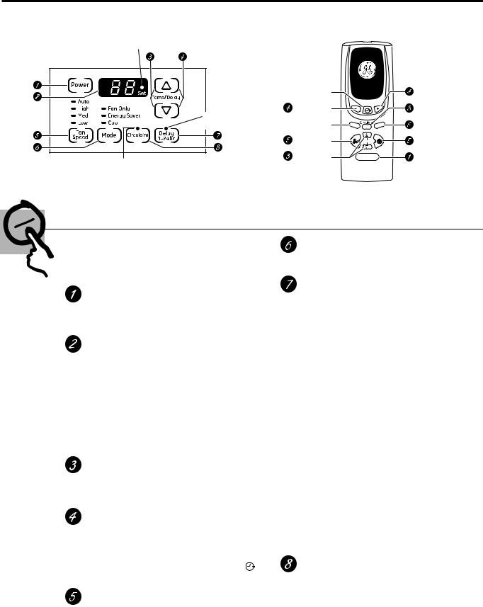
About the controls on the air conditioner—models with touch pads.
Lights next to the touch pads on the air conditioner control panel indicate the selected settings.
The display always shows the room |
Light indicates the unit |
is in the temperature or |
|
temperature except when setting the |
delay time Set mode. |
Set temperature or the Delay timer. |
|
Light indicates the delay timer is set.
Light indicates
Circulaire is on.
Air Conditioner Controls
 Delay 1–24hr
Delay timer Decrease  Mode select
Fan speed 
Decrease
Temperature |
set Increase |
and Decrease |
|
|
Delay |
|
M |
ode |
|
o |
|
Aut |
||
|
|
Fan |
|
|
- |
F |
a |
n |
|
||
a |
|
|
n |
F |
|
|
+ |
Temp
Power
Remote Control
Delay timer Increase
Circulaire
Auto Fan on/off
Fan speed Increase
Unit power on/off
Controls
The air conditioner controls are located behind the control panel door. Press to open and close the door.
NOTE: The remote control will work with the control panel door open or closed.
Power Pad
Turns air conditioner on and off. When turned on, the display will show the room temperature.
Display
Shows the room temperature or time remaining on the Delay timer. Shows the Set temperature while setting the temperature in Cool or Energy Saver modes. The Set light will turn on while setting.
NOTE: The display will change to show the room temperature after settings have been made. To recall the Set temperature, press the
Temp Increase ▲ or Decrease ▼ pads.
Temp Increase ▲ /Decrease ▼ Pads
Use to set temperature when in Cool or Energy Saver mode. The Set light will turn on while setting.
Delay Timer Increase ▲ (+) /Decrease ▼ (–)
Pads
Mode Pad
Use to set the air conditioner to Cool, Energy Saver or Fan Only mode.
Delay Pads
Delay ON—When the air conditioner is off, it can be set to automatically come on in 1 to 24 hours at its previous mode and fan settings.
Delay OFF—When the air conditioner is on, it can be set to automatically turn off in 1 to 24 hours.
How to set:
Press the Delay 1–24hr pad on the unit or
the pad on the remote control. Each touch of the Increase ▲ / Decrease ▼ pads on the unit or the Increase + / Decrease – pads on the remote control will set the timer in 1-hour intervals. The Set light will turn on while setting.
To review the remaining time on the Delay 1–24hr timer, press the Delay 1–24hr pad on the unit or the pad on the remote control. Use the Increase ▲ / Decrease ▼ pads on the unit or the Increase + / Decrease – pads on the remote control to set a new time if desired.
Each touch of the Increase ▲ / Decrease ▼ |
To cancel the timer, press the Delay 1–24hr pad |
|
pads on the unit or the Increase + / Decrease – |
until the light on the Delay 1–24hr pad goes off. |
|
pads on the remote control will set the delay |
CIRCULAIRE Pad |
|
time when using the Delay 1–24hr timer ( ). |
||
Turn on to provide continuous side-to-side |
||
The Set light will turn on while setting. |
||
air circulation. |
||
|
Fan Speed Pads
Use to set the fan speed to Low, Med, High or Auto on the unit. NOTE: On the remote control, use the fan speed Increase + / Decrease – pads to set the fan speeds to Low, Med or High. Use the Auto pad to turn Auto
fan on.
4
For fixed side-to-side air direction, turn on until the desired air direction is obtained, then turn it off.

ge.com
Do Not Operate in Freezing Outdoor Conditions
This cool-only air conditioner was not designed for freezing outdoor conditions. It must not be used in freezing outdoor conditions.
Cool Mode
Use the Cool mode at Low, Med, High or Auto Fan Speed for cooling. Use the Temperature Increase ▲ / Decrease ▼ pads to set the desired temperature between 64°F and 86°F in 1°F increments.
An electronic thermostat is used to maintain the room temperature. The compressor will cycle on and off to keep the room at the set level of comfort. Set the thermostat at a lower number and the indoor air will become cooler. Set the thermostat at a higher number and the indoor air will become warmer.
NOTE: If the air conditioner is off and is then turned on while set to a Cool setting or if turned from a fan setting to a Cool setting, it may take approximately 3 minutes for the compressor to start and cooling to begin.
Cooling Descriptions
For Normal Cooling—Select the Cool mode and
High or Med fan with a middle set temperature.
For Maximum Cooling—Select the Cool mode and High fan with a lower set temperature.
For Quieter & Nighttime Cooling—Select the
Cool mode and Low fan with a middle set temperature.
Energy Saver Mode
Controls the fan.
ON—The fan will cycle on and off with the compressor. This results in wider variations of room temperature and humidity. Normally used when the room is unoccupied. NOTE: The fan may continue to run for a short time after the compressor cycles off.
OFF—The fan runs all the time, while the compressor cycles on and off.
Fan Only Mode
Use the Fan Only Mode at Low, Med or High fan speed to provide air circulation and filtering without cooling. Since fan only settings do not provide cooling, a Set temperature cannot be entered. The room temperature will appear in the display.
NOTE: Auto Fan Speed cannot be used when in the
Fan Only Mode.
Auto Fan Speed
Set to Auto fan speed for the fan speed to automatically set to the speed needed to provide optimum comfort settings with the set temperature.
If the room needs more cooling, the fan speed will automatically increase. If the room needs less cooling, the fan speed will automatically decrease.
NOTE: Auto Fan Speed cannot be used when in the
Fan Only Mode.
Power Outage Recovery Feature
In the case of a power outage or interruption, the |
feature was set, it will resume countdown. You may |
unit will automatically re-start in the settings last |
need to set a new time if desired. |
used after the power is restored. If the Delay 1–24hr |
|
|
|
Remote Control
■To ensure proper operation, aim the remote control at the signal receiver on the air conditioner.
■The remote control signal has a range of up to 20 feet.
■Make sure nothing is between the air conditioner and the remote control that could block the signal.
■Make sure batteries are fresh and installed
correctly as indicated on the remote control. 5
Instructions Safety |
||
|
|
|
Instructions |
Operating |
|
|
||
Cleaning and Care |
||
|
|
|
Instructions |
Installation |
|
|
||
Tips Troubleshooting |
||
|
||
Support Consumer |
||
|
|
|
Safety Instructions |
||
|
|
|
Operating |
Instructions |
|
|
||
Care and Cleaning |
||
|
|
|
Installation |
Instructions |
|
|
||
Troubleshooting Tips |
||
|
||
Consumer Support |
||
|
|
|
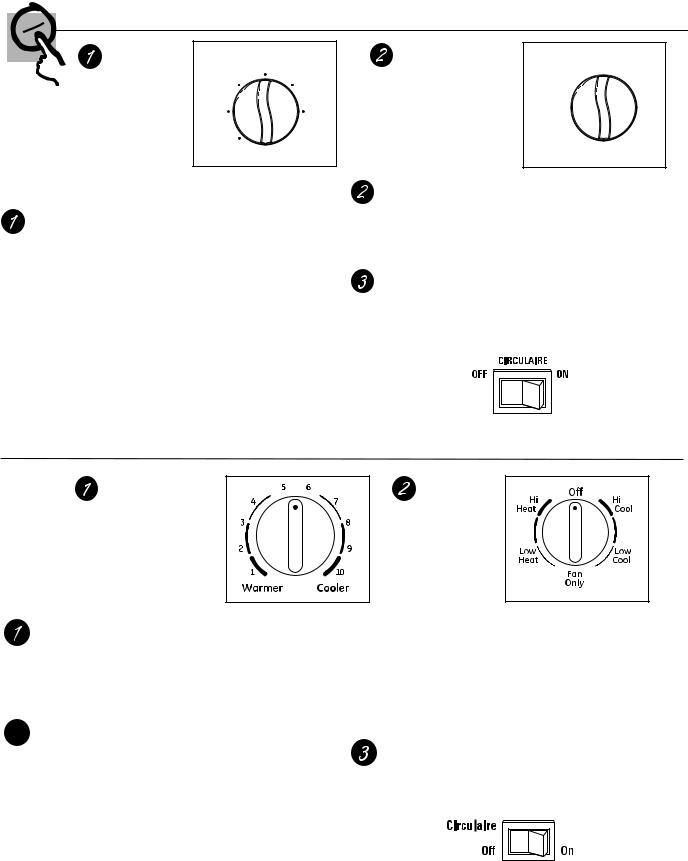
About the controls on the air conditioner—models with control knobs.
Features and appearance will vary.
Controls
MODE |
MODE |
|
TEMPERATURE |
|
|
CONTROL |
OFF |
High |
CONTROL |
Coolest 7 |
TEMP |
High |
1 |
||||
(on some models) |
Cool |
Fan |
(on some models) |
|
|
|
|
|
|
||
|
Med |
Low |
|
6 |
2 |
|
Cool |
Fan |
|
|
|
|
Low |
|
|
5 |
3 |
|
|
|
|
4 |
|
|
Cool |
|
|
|
|
|
|
|
|
|
The air conditioner controls are located behind the control panel door. Press to open and close the door.
Mode Control
High Cool, Med Cool and Low Cool provide cooling with different fan speeds.
Fan settings provide air circulation and filtering without cooling.
NOTE: If you move the mode control from a cool setting to OFF or to a fan setting, wait at least 3 minutes before switching back to a cool setting.
Cooling Descriptions
For Normal Cooling—Select High Cool or Med Cool with the TEMPERATURE control at midpoint.
For Maximum Cooling—Select High Cool with the TEMPERATURE control at the highest number available on your knob.
For Quieter & Nighttime Cooling—Select Low Cool with the TEMPERATURE control at midpoint.
TEMP Control
The TEMP control is used to maintain the room temperature. The compressor will cycle on and off to keep the room at the same level of comfort. When you turn the knob to a higher number, the indoor air will become cooler. Turn the knob to a lower number and the indoor air will become warmer.
CIRCULAIRE
For continuous side-to-side air circulation, set the Circulaire switch to ON.
For fixed side-to-side air direction, set the Circulaire switch to ON until the desired air direction is obtained, then move it to OFF.
TEMPERATURE CONTROL
(on some models)
Temp Control
The temp control is used to maintain the room temperature. The compressor will cycle on and off to keep the room at the same level of comfort. Turn the knob clockwise to Cooler (blue) and indoor air will become cooler. Turn knob counterclockwise to Warmer (red) and the indoor air will become warmer.
 Mode Control
Hi Cool and Low Cool provide cooling with different fan speeds. Hi Heat and Low Heat provide heating with different fan speeds.
Fan Only setting provides air circulation and filtering without cooling or heating.
NOTE: If you move the mode control from a cool setting to Off, a fan setting or a heat setting, wait at least 3 minutes before switching back to a cool setting.
Cooling Descriptions
For Normal Cooling—Select Hi Cool or Low Cool with the temp control at midpoint.
For Maximum Cooling—Select Hi Cool with the temp control turned clockwise as far as possible.
For Quieter & Nighttime Cooling—Select Low Cool with the temp control at midpoint.
MODE CONTROL
(on some models)
Heating Descriptions
For Normal Heating—Select Hi Heat or Low Heat with the temp control at midpoint.
For Maximum Heating—Select Hi Heat with the temp control turned counterclockwise as far as possible.
For Quieter & Nighttime Heating—Select Low Heat with the temp control at midpoint.
Circulaire
For continuous side-to-side air circulation, set the Circulaire switch to On.
For fixed side-to-side air direction, set the Circulaire switch to On until the desired air direction is obtained, then move it to Off.
Additional controls. |
ge.com |
Vent Control
The vent control is located above the control panels.
When set at CLOSE, only the air inside the room will be circulated and conditioned. When set at OPEN, some outside air is let into the room.
To open the vent, push the lever to the right.
To close it, push it to the left.
Air Direction—Up and Down
Fingertip pressure on the horizontal louvers adjusts the air direction up or down.
Control Panel Door
Press to open and close the door.
NOTE: The remote control (on some models) will work with the control panel door open or closed.
Normal operating sounds.
■You may hear a pinging noise caused by water being picked up and thrown against the
condenser on rainy days or when the humidity is high. This design feature helps remove moisture and improve efficiency.
■You may hear the thermostat click when the compressor cycles on and off.
■Water will collect in the base pan during
high humidity or on rainy days. The water may overflow and drip from the outdoor side of the unit.
■The fan may run even when the compressor does not.
7
Instructions Safety |
||
|
|
|
Instructions |
Operating |
|
|
||
Cleaning and Care |
||
|
|
|
Instructions |
Installation |
|
|
||
Tips Troubleshooting |
||
|
||
Support Consumer |
||
|
|
|
Safety Instructions |
||
|
|
|
Operating |
Instructions |
|
|
||
Care and Cleaning |
||
|
|
|
Installation |
Instructions |
|
|
||
Troubleshooting Tips |
||
|
||
Consumer Support |
||
|
|
|
Care and cleaning of the air conditioner.
Grille and Case
Turn the air conditioner off and remove the |
To clean, use water and a mild detergent. Do not |
plug from the wall outlet before cleaning. |
use bleach or abrasives. |
Outdoor Coils
The coils on the outdoor side of the air conditioner should be checked regularly. If they are clogged with dirt or soot, they may be professionally cleaned.
Air Filter
The air filter behind the front grille should be checked and cleaned at least every 30 days or more often if necessary.
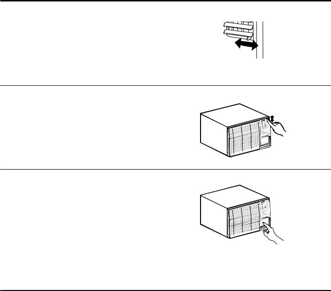
To remove:
1 |
Open the inlet grille upward by pulling out the |
|
bottom of the inlet grille. |
||
|
||
|
Using the tab, pull up slightly on the filter |
|
2 |
||
to release it and pull it down. |
||
|
Clean the filter with warm, soapy water. Rinse and
let the filter dry before replacing it. Do not clean
the filter in a dishwasher.  CAUTION:DO NOT operate the air conditioner without a filter because dirt and lint will clog it and reduce performance.
Grille Frame Removal (if necessary for coil cleaning)
Remove the air filter. See the Air Filter section above.
If present, remove the grille frame attachment screw.
Grasp the lower corners of the grille frame while pressing in on the case side tabs with your finger tips. Pull out to release and lift it up.
NOTE: Do not pull the bottom edge toward you more than 3″ or you may damage the tabs of the grille.
How to Insert the Batteries in the Remote Control
1
2
3
8
Remove the battery cover by sliding it according to the arrow direction.
Insert new batteries, making sure that the (+) and (–) of battery are installed correctly.
Reattach the cover by sliding it back into position.
NOTES:
■Use 2 “AAA” (1.5 volt) alkaline batteries. Do not use rechargeable batteries.
■Remove the batteries from the remote control if the system is not going to be used for a long time.
Installation |
Air Conditioner |
Instructions |
|
Questions? Call 800.GE.CARES (800.432.2737) or visit our Website at: ge.com
In Canada, call 1.800.561.3344 or visit www.GEAppliances.ca
 BEFORE YOU BEGIN
Read these instructions completely and carefully.
• IMPORTANT — Save these
instructions for local inspector’s use.
• IMPORTANT — Observe all governing codes and ordinances.
•Note to Installer – Be sure to leave these instructions with the Consumer.
•Note to Consumer – Keep these instructions for future reference.
•Skill level – Installation of this appliance requires basic mechanical skills.
•Completion time – Approximately 1 hour
•We recommend that two people install this product.
•Proper installation is the responsibility of the installer.
•Product failure due to improper installation is not covered under the Warranty.
•You MUST use all supplied parts and use proper installation procedures as described in these instructions when installing this air conditioner.
 ELECTRICAL REQUIREMENTS
The 3-prong grounding plug minimizes the possibility of electric shock hazard. If the wall outlet you plan to use is only a 2-prong outlet, it is your responsibility to have it replaced with a properly grounded 3-prong wall outlet.
Some models require 230/208-volt a.c., protected with a time delay fuse or circuit breaker.These models should be installed on their own single branch circuit for best performance and to prevent overloading house or apartment wiring circuits, which could cause a possible fire hazard from overheating wires.
 CAUTION:
Do not, under any circumstances, cut or remove the third (ground) prong from the power cord.
Do not change the plug on the power cord of this air conditioner.
Aluminum house wiring may present special problems—consult a qualified electrician.
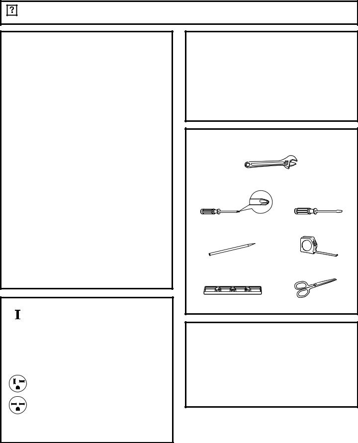
TOOLS YOU WILL NEED |
|
Adjustable wrench |
|
Phillips head screwdriver |
Flat-blade screwdriver |
Pencil |
Ruler or tape measure |
Level |
Scissors or knife |
Power cord includes a current interrupter device. A test and reset button is provided on the plug case.The device should be tested on a periodic basis by first pressing the TEST button and then the RESET button while plugged into the outlet. If the TEST button does not trip or
if the RESET button will not stay engaged, discontinue use of the air conditioner and contact a qualified service technician.
9
Window Installation Instructions
PARTS INCLUDED |
|
|
|
Window |
|
|
(Appearance may vary) |
|
|
|
|
||
|
|
|
|
|
sash seal |
|
Left |
|
|
|
|
|
|
accordion |
|
|
|
|
|
|
panel |
|
|
Foam top |
|
|
|
|
|
Top |
|
|
|
|
|
|
window gasket |
|
|
||
|
|
mounting |
|
|
|
|
|
|
rail |
|
|
|
|
|
|
|
|
|
|
Right |
|
|
|
|
|
accordion |
|
|
|
|
|
|
|
panel |
|
|
|
V-support (2) |
|
|
|
Window locking |
|
|
|
|
|
|
bracket (2) |
|
|
Bolt (2) and nuts (2) |
|
|
|
|
|
|
|
|
||
|
|
|
|
Top mounting rail |
|
|
|
|
|
|
|
seal strip |
|
Type A (6) |
Type B (4) |
Type C (7) |
Type D (6) |
Type E (4) |
Type F (2) |
|
|
|
|
10 |
|
|
|
Window Installation Instructions
1WINDOW REQUIREMENTS
•These instructions are for a standard double-hung window.You will need to modify them for other types of windows.
•The air conditioner can be installed without the accordion panels if needed to fit in a narrow window. See the window opening dimensions.
•All supporting parts must be secured to firm wood, masonry or metal.
•The electrical outlet must be within reach of the power cord.
18″ min.
30″ to 41″
(With accordion panels)
3ATTACH THE TOP MOUNTING RAIL SEAL STRIP
Remove the backing from the top mounting rail seal strip and attach the seal strip to the bottom of the top mounting rail, along the front edge.
Top mounting rail
Remove backing from seal strip
FRONT VIEW |
Top mounting rail |
||
|
|
|
|
|
|
|
|
|
|
|
|
Seal strip
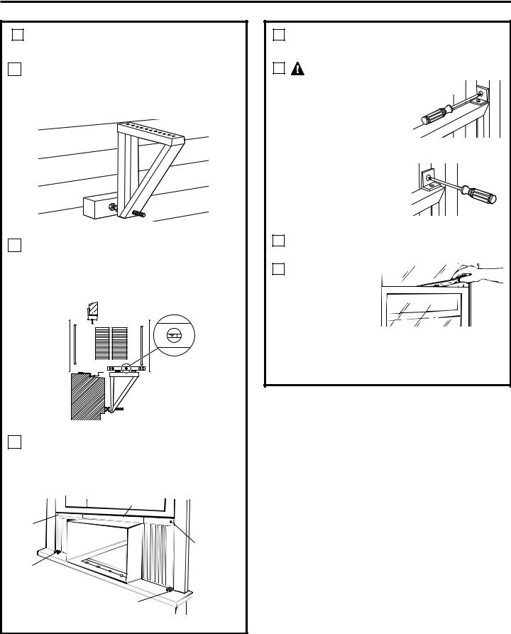
2 STORM WINDOW REQUIREMENTS
A storm window frame will not allow the air conditioner to tilt toward the outside, and will keep it from draining properly.
To adjust for this, attach a piece of wood to the stool.
WOOD PIECES WIDTH: 2″
LENGTH: Long enough to fit inside the window frame.
THICKNESS: To determine the thickness, place a piece of wood on the sill to make it 1/2″ higher than the top of the storm window frame or the vinyl frame.
Attach securely with nails or screws provided by the installer.
|
1/2″ higher |
|
|
than vinyl frame |
|
|
(on some windows) |
|
1/2″ higher |
Wood |
|
|
||
than storm |
|
|
window |
Sill |
|
frame |
||
|
||
Storm window |
Vinyl frame |
|
frame |
||
|
11
4REMOVE THE AIR CONDITIONER FROM THE CASE
ARemove the locking screw and locking bracket from the lower frame. Save to reinstall later.
BRemovelater. the ground screw and save to reinstall
Remove the ground screw and save to reinstall later
CSlide the air conditioner from the case by gripping the base pan handle and pulling forward while bracing the case.

Window Installation Instructions
5 PREPARE THE WINDOW
Cut the window sash seal to the proper length. Peel off the backing and attach the seal to the underside of the window sash.
6 PREPARE THE CASE
AInstall the top mounting rail with 4 type B screws from the inside of the case.
Top mounting rail
BInsert the frames for the accordion panels into the top mounting rail and the bottom frame guides. Attach the accordion panels to the side of the case using 3 type A screws on each side.
Note: When attaching the accordion panels, make sure to only screw the inner panels to the case sides.
Top mounting rail
Type A |
BACK |
|
screws |
||
|
||
|
Bottom mounting rail |
7INSTALL THE CASE IN THE WINDOW
ACarefully slide the case into the window and center the case. Lower the window behind the top mounting rail. Pull the bottom of the case forward so that the bottom mounting rail is tight against the back of the window sill. Mount the case to the window sill using 4 type E screws. Drill pilot holes, if necessary.
4 type E screws
Sill
BMake sure the bolts and nuts are all of the way in both the left and right V-supports.
Bolt and nut
CPosition the V-supports on the case bottom so that they will be near the outside wall. Attach a V-support to each side of the bottom of the case using type C screws,
3 on each side.
 V-support
12
Window Installation Instructions
7INSTALL THE CASE
IN THE WINDOW (cont.)
DUse a wood block (obtained locally) between the leveling bolts and the wall if the wall is weak or if the weight of the air conditioner falls between the studs in the wall.
EAdjust the leveling bolts and nuts against the outside wall so that the case has a slight tilt to the outside.Tighten nuts with an adjustable wrench. Use a level; no more than a 1/2 bubble will be the correct case slant to the outside.
FExtend the left and right accordion panels to the vertical window sashes. Drill pilot holes and attach the top and bottom corners with 4 type D screws.
Top mounting rail
Type D
screw Type D screw
Type D screw
Type D screw
8INSTALL SUPPORT BRACKETS AND FOAM TOP WINDOW GASKET
A |
CAUTION: |
|
|
To prevent broken glass |
Vinyl |
|
or damage to windows, |
|
|
on vinyl or other |
|
|
similarly constructed |
|
|
windows, attach the |
|
|
support bracket to the |
|
|
window side jam. |
|
|
Drill pilot holes and |
Wood |
|
attach the support |
|
|
brackets with two type |
|
|
D screws, one on each |
|
|
side. |
|
BCut the foam top window gasket to the window width.
C Stuff the foam between the glass and the window to
prevent air and
insects from getting into the room.
NOTE: If the gasket supplied does not fit your window, obtain appropriate material locally to provide a proper installation seal.
13
Window Installation Instructions
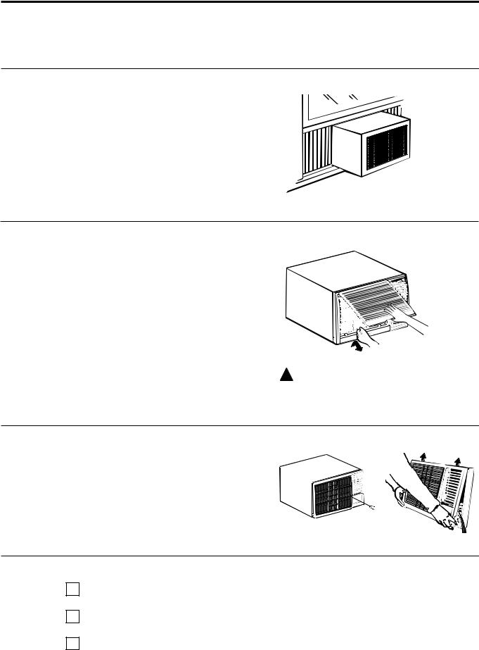
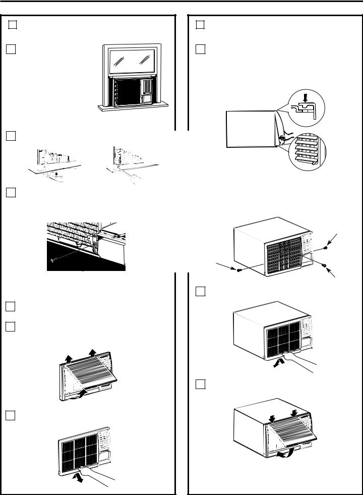
9INSTALL THE AIR CONDITIONER IN THE CASE
AMake sure the ground wire is off to the side
and slide the air conditioner into the case. Do not push on the controls or the finned coils. Make sure the air conditioner is
firmly seated.
BReinstall the locking bracket and screw removed earlier.
CReconnect the ground wire to the air conditioner using the screw removed earlier.
IMPORTANT:The ground wire must be reinstalled to ensure a proper ground.
9INSTALL THE AIR CONDITIONER IN THE CASE (cont.)
GPull the coiled power cord from its shipped position in the air discharge area. Attach the front grille frame to the case by inserting the tabs on the grille frame into the slots
on the front top of the case.
Guide the lever carefully through the grille frame as you push it in.
HPress the grille frame in around the power cord on the right side. Secure the grille with a type F (painted) screw on each side and a type C screw in the front.
Type F screw
D
E
F
Press the ground wire against the unit to prevent it from being pinched when installing the front grille
Remove the front grille from its box and remove the shipping tape.
Grasp the inlet grille at the bottom corners and pull it forward. Unhook it from its top hinges and set it aside.
Using the tab, pull up slightly on the filter to release it and pull it down and out.
Type F screw
Type C screw
I Reinstall the filter.
J Reinstall the inlet grille. Connect power.
Caulk or weather-strip any gaps or openings
to the outside to seal the installation.
14
Through-the-Wall Installation Instructions—Optional
The case may be installed through-the-wall in both existing and new construction.
Read completely, then follow step-by-step.
NOTE: Except for the V-support assemblies (included), obtain all materials locally for mounting the air conditioner through-the-wall.
1 IMPORTANT
Through-the-wall installation is not appropriate if any of the side or top louvers in the case will be obstructed by the wall.
All side and top louvers in the case must project on the outdoor side of the wall.
The room side of the case must project into the room far enough to maximize the balance of the unit.
The case must be installed level from side- to-side and with a slight tilt from front to rear. Use a level; no more than a 1/2 bubble will be the correct case slant to the outside.
Lintel angle is required to support bricks or blocks above opening.
Flashing is required and should extend the length of the opening to ensure no inside cavity leakage occurs.
ARemove the air conditioner from the case. For specific instruction, refer to the Window Installation Instructions.
BMake certain that a wall receptacle is available close to the hole location or make arrangements to install a receptacle.
CPlace the case in the wall opening and place wood support strips between the case bottom and the flashing on both sides of the bottom rail.They should be the same height as the bottom rail and the same length as the wall opening.
1 IMPORTANT (cont.)
DSecure with 14 wood screws anchored at least an inch into the wall support structure.
NOTE: Drill pilot holes, if necessary, for proper installation. If the frame is oversized, use shims to prevent case distortion.
EInstall the V-supports. See the INSTALL THE CASE IN THE WINDOW section in the Window Installation Instructions.
2 FINISH THE WALL OPENING
ACaulk all four sides on the outdoor side of the case to prevent moisture from getting through to the interior wall. Use of flashing (drip rail) will further prevent water from dripping inside the wall and down the outside of the building.
|
Plaster line |
|
Lintel angle |
|
|
Caulking |
Trim molding |
|
|
(if desired) |
|
OUTSIDE |
INSIDE |
|
|
||
Air louvers |
|
|
(top and |
Bottom rail |
|
sides must |
||
|
||
project on the |
|
|
outdoor side |
|
|
of the wall) |
|
Wood filler and caulking (above and below the flashing)
V-supports
Case Bottom Flashing bottom rail (Drip rail)
Flashing
(Drip rail)
Wood support strips
BPlace the air conditioner into the case.
For specific instruction, refer to the Window Installation Instructions.
15

Safety Instructions |
||
|
|
|
Operating |
Instructions |
|
|
||
Care and Cleaning |
||
|
|
|
Installation |
Instructions |
|
|
||
Troubleshooting Tips |
||
|
||
Consumer Support |
||
|
|
|
Troubleshooting Tips.
Problem |
|
Possible Causes |
What To Do |
|
|
|
|
Air conditioner |
|
The air conditioner |
• Make sure the air conditioner plug is pushed completely |
does not start |
|
is unplugged. |
into the outlet. |
|
|
|
|
|
|
The fuse is blown/circuit |
• Check the house fuse/circuit breaker box and replace |
|
|
breaker is tripped. |
the fuse or reset the breaker. |
|
|
|
|
|
|
Power failure. |
• The unit will automatically re-start in the settings last |
|
|
|
used after the power is restored. |
|
|
|
• There is a protective time delay (approximately 3 minutes) |
|
|
|
to prevent tripping of the compressor overload. For this |
|
|
|
reason, the unit may not start normal cooling for |
|
|
|
3 minutes after it is turned back on. |
|
|
|
|
|
|
The current interrupter |
• Press the RESET button located on the power cord plug. |
|
|
device is tripped. |
• If the RESET button will not stay engaged, discontinue |
|
|
|
use of the air conditioner and contact a qualified service |
|
|
|
technician. |
Air conditioner does not |
|
Airflow is restricted. |
• Make sure there are no curtains, blinds or furniture |
cool as it should |
|
|
blocking the front of the air conditioner. |
|
|
|
|
|
|
The temp control may not |
• On models with touch pads: In the Cool mode, press the |
|
|
be set correctly. |
Decrease ▼ pad. |
|
|
|
• On models with control knobs, turn the temperature |
|
|
|
knob to a higher number. |
|
|
|
|
|
|
The air filter is dirty. |
• Clean the filter at least every 30 days. See the |
|
|
|
Care and Cleaning section. |
|
|
|
|
|
|
The room may have been hot. |
• When the air conditioner is first turned on, you need to |
|
|
|
allow time for the room to cool down. |
|
|
|
|
|
|
Cold air is escaping. |
• Check for open furnace floor registers and cold air returns. |
|
|
|
• Set the air conditioner’s vent to the closed position. |
|
|
|
|
|
|
Cooling coils have iced up. |
• See “Air conditioner freezing up” below. |
|
|
|
|
Air conditioner |
|
Ice blocks the air flow and |
• On models with control knobs, set the mode control at |
freezing up |
|
stops the air conditioner |
High Fan or High Cool with the Temp at 1 or 2. |
|
|
from cooling the room. |
• On models with touch pads, set the controls at High Fan |
|
|
|
or High Cool and set the thermostat to a higher |
|
|
|
temperature. |
The remote control |
|
The batteries are inserted |
• Check the position of the batteries. They should be |
is not working |
|
incorrectly. |
inserted in the opposite (+) and (–) direction. |
|
|
|
|
|
|
The batteries may be dead. |
• Replace the batteries. |
|
|
|
|
Water drips outside |
|
Excessively hot and |
• This is normal. |
|
|
humid weather. |
|
|
|
|
|
Water drips indoors |
|
The air conditioner is not |
• For proper water disposal, make sure the air conditioner |
|
|
tilted to the outside. |
slants slightly from the case front to the rear. |
Water collects in |
|
Moisture is removed from |
• This is normal for a short period in areas with little |
base pan |
|
indoor air and drains into |
humidity; normal for a longer period in very humid areas. |
|
|
rear of a cabinet where a fan |
|
|
|
blows it against the outdoor |
|
|
|
condenser coil. |
|
Delay 1–24hr feature not |
|
A power outage or interruption |
• The unit will automatically re-start in the settings last used |
working properly |
|
occurred. |
after the power is restored. If the Delay 1–24hr feature was |
|
|
|
set, it will resume countdown. You may need to set a new |
|
|
|
time if desired. |
|
|
|
|
16

Please place in envelope and mail to:
Veuillez mettre dans une enveloppe et envoyez à :
OWNERSHIP REGISTRATION
P.O. BOX 1780
MISSISSAUGA, ONTARIO
L4Y 4G1
(FOR CANADIAN CONSUMERS ONLY)
17
18
 Loading...