


 Loading...
Gateway Series
G100 / G200 / G400 / G800
Administrator Manual
601-00020 |
Rev. B |

Digium, Inc.
445 Jan Davis Drive
Huntsville, AL 35806
United States
Main Number: +1 (256)-428-6000
Tech Support: +1 (256)-428-6161
U.S. Toll Free: +1 (877)-344-4861
Sales: +1 (256)-428-6262
www.digium.com
www.asterisk.org
www.asterisknow.org
© Digium, Inc. 2013 All rights reserved.
No part of this publication may be copied, distributed, transmitted, transcribed, stored in a retrieval system, or translated into any human or computer language without the prior written permission of Digium, Inc.
Digium, Inc. has made every effort to ensure that the instructions contained in this document are adequate and error free. The manufacturer will, if necessary, explain issues which may not be covered by this documentation. The manufacturer’s liability for any errors in the documents is limited to the correction of errors and the aforementioned advisory services.
This document has been prepared for use by professional and properly trained personnel, and the customer assumes full responsibility when using it.
Adobe and Acrobat are registered trademarks, and Acrobat Reader is a trademark of Adobe Systems Incorporated.
Asterisk, Digium, Switchvox, and AsteriskNOW are registered trademarks and Asterisk Business Edition, AsteriskGUI, and Asterisk Appliance are trademarks of Digium, Inc.
Any other trademarks mentioned in the document are the property of their respective owners.
Digium, Inc. |
Page 2 |

Compliance Information
Compliance information for this product is available at http://www.digium.com/compliance.
Digium, Inc. |
Page 3 |

Introduction to Gateway Series Documentation
This manual contains product information for the Gateway Series appliances. Be sure to refer to any supplementary documents or release notes that were shipped with your equipment. The manual is organized in the following manner:
Chapter/ |
Title |
Description |
|
Appendix |
|||
|
|
||
|
|
|
|
1 |
Overview |
Identifies the features of your unit. |
|
|
|
|
|
2 |
Unit Installation |
Provides instructions for installing the unit. |
|
|
|
|
|
3 |
Configuration |
Provides instructions on how to configure the unit. |
|
|
|
|
|
4 |
Troubleshooting |
Explains resolutions to common problems and |
|
|
|
frequently asked questions pertaining to unit |
|
|
|
installation and usage. |
|
|
|
|
|
A |
Pin Assignments |
Describes the states supported by the unit. |
|
|
|
|
|
B |
Specifications |
Details unit specifications. |
|
|
|
|
|
C |
Glossary and |
Defines terms related to this product. |
|
|
Acronyms |
|
|
|
|
|
Digium, Inc. |
Page 4 |

Symbol Definitions
Caution statements indicate a condition where damage to the unit or its configuration could occur if operational procedures are not followed. To reduce the risk of damage or injury, follow all steps or procedures as instructed.
The ESD symbol indicates electrostatic sensitive devices. Observe precautions for handling devices. Wear a properly grounded electrostatic discharge (ESD) wrist strap while handling the device.
The Electrical Hazard Symbol indicates a possibility of electrical shock when operating this unit in certain situations. To reduce the risk of damage or injury, follow all steps or procedures as instructed.
Digium, Inc. |
Page 5 |
Important Safety Instructions
Servicing.
Do not attempt to service this unit. There are no user-serviceable parts inside. Refer servicing to qualified service personnel.
Batteries.
The batteries in the unit are not user-serviceable. Refer servicing to qualified service personnel.
CAUTION - Risk of explosion if battery is replaced by an incorrect type. Batteries should be disposed of according to the local laws and regulations of your region.
ATTENTION - II y a danger d’explosion s’il y a remplacement incorrect de la batterie. Remplacer uniquement avec une batterie du même type ou d’un type equivalent recommandé par le constructeur.Mettre au rebut les batteries usages conformément aux instructions du fabricant.
Water and Moisture.
Do not spill liquids on this unit. Do not operate this equipment in a wet environment.
Heat.
Do not operate or store this product near heat sources such as radiators, air ducts, areas subject to direct, intense sunlight, or other products that produce heat.
Caution.
To reduce the risk of fire, use only No. 26 AWG or larger telecommunication wiring for network connections.
Static Electricity.
To reduce the risk of damaging the unit or your equipment, do not attempt to open the enclosure or gain access to areas where you are not instructed to do so. Refer servicing to qualified service personnel.
Save these instructions for future reference.
Digium, Inc. |
Page 6 |

TABLE OF CONTENTS
Chapter 1
Overview . . . . . . . . . . . . . . . . . . . . . . . . . . . . . . . . . . . . . . . . . . . . . . .11
Echo-Cancellation . . . . . . . . . . . . . . . . . . . . . . . . . . . . . . . . . . . . . .15
Chapter 2
Unit Installation . . . . . . . . . . . . . . . . . . . . . . . . . . . . . . . . . . . . . . . . . .16
Unpacking the Unit . . . . . . . . . . . . . . . . . . . . . . . . . . . . . . . . . . . . .17 Shipment Inspection . . . . . . . . . . . . . . . . . . . . . . . . . . . . . . . . . . . .18 Front Panel Identification . . . . . . . . . . . . . . . . . . . . . . . . . . . . . . . .19 Unit Identification . . . . . . . . . . . . . . . . . . . . . . . . . . . . . . . . . . . . . .23 Hardware Installation . . . . . . . . . . . . . . . . . . . . . . . . . . . . . . . . . . .24 Connecting to the Gateway Series . . . . . . . . . . . . . . . . . . . . . . . . .33
Chapter 3
Configuration . . . . . . . . . . . . . . . . . . . . . . . . . . . . . . . . . . . . . . . . . . . .45
Settings and Configuration . . . . . . . . . . . . . . . . . . . . . . . . . . . . . . .49
Logging and Reporting . . . . . . . . . . . . . . . . . . . . . . . . . . . . . . . . . .65
Status and Diagnostics . . . . . . . . . . . . . . . . . . . . . . . . . . . . . . . . . .66
Maintenance . . . . . . . . . . . . . . . . . . . . . . . . . . . . . . . . . . . . . . . . . .72
Chapter 4
Troubleshooting . . . . . . . . . . . . . . . . . . . . . . . . . . . . . . . . . . . . . . . . .77
Frequently Asked Questions . . . . . . . . . . . . . . . . . . . . . . . . . . . . . .80
Free Installation Support . . . . . . . . . . . . . . . . . . . . . . . . . . . . . . . . .84
Digium, Inc. |
Page 7 |

Table Of Contents
Appendix A
Pin Assignments . . . . . . . . . . . . . . . . . . . . . . . . . . . . . . . . . . . . . . . . .85
Appendix B
Specifications . . . . . . . . . . . . . . . . . . . . . . . . . . . . . . . . . . . . . . . . . . .87
Appendix C
Glossary and Acronyms . . . . . . . . . . . . . . . . . . . . . . . . . . . . . . . . . . .89
Digium, Inc. |
Page 8 |

List of Figures
Figure 1: TDM PBX to VoIP Scenario . . . . . . . . . . . . . . . . . . .13 Figure 2: VoIP PBX to TDM Scenario . . . . . . . . . . . . . . . . . . .13 Figure 3: TDM PBX to TDM and VoIP Scenario . . . . . . . . . . .14 Figure 4: G100 Single Port Appliance . . . . . . . . . . . . . . . . . . .19 Figure 5: G200 Dual Port Appliance . . . . . . . . . . . . . . . . . . . .20 Figure 6: G800 Octal Port Appliance . . . . . . . . . . . . . . . . . . . .21 Figure 7: Side-by-side Rack Mounting . . . . . . . . . . . . . . . . . . .29 Figure 8: Acceptable Wall Mount Orientation . . . . . . . . . . . . .30 Figure 9: IP Configuration Menu for G100 / G200 . . . . . . . . . .36 Figure 10: IP Configuration Menu for G400 / G800 . . . . . . . . . .40 Figure 11: Login Screen . . . . . . . . . . . . . . . . . . . . . . . . . . . . . . .46 Figure 12: Main Menu . . . . . . . . . . . . . . . . . . . . . . . . . . . . . . . .48
Digium, Inc. |
Page 9 |

List of Tables
Table 1: Gateway Series Models. . . . . . . . . . . . . . . . . . . . . . 23 Table A-1: Gigabit Ethernet Port Pinouts . . . . . . . . . . . . . . . . . .85 Table A-2: RJ45 T1/E1 Port Connector. . . . . . . . . . . . . . . . . . . .86
Digium, Inc. |
Page 10 |
Chapter 1
Overview
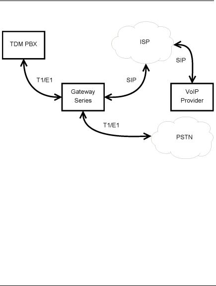
Digium's Gateway Series is a converged media gateway product line designed to interface between TDM (T1/E1) and IP networks (SIP). The Gateway Series connects legacy telephone systems to IP networks and seamlessly integrates VoIP PBXs with the PSTN. Powered by innovative hardware and software solutions, Digium’s Gateway Series are managed by a simple, intuitive web-based interface.
Digium, Inc. |
Page 11 |

Chapter 1: Overview
Supported Voice Modes:
PRI CPE and PRI NET (T1 / E1)
–National ISDN 1 / NI1
–National ISDN 2 / NI2
–EuroISDN
–4ESS (AT&T)
–5ESS (Lucent)
–DMS100
–Q.SIG
E&M (T1 only)
–Wink
–Feature Group B
–Feature Group D
FXO and FXS (T1 only)
–Ground Start
–Loop Start
–Loop Start with Disconnect Detect (Kewlstart)
SIP
Example scenarios utilizing the Gateway Series are illustrated in Figure 1, Figure 2, and Figure 3.
Digium, Inc. |
Page 12 |

Chapter 1: Overview
Figure 1: TDM PBX to VoIP Scenario
Figure 2: VoIP PBX to TDM Scenario
Digium, Inc. |
Page 13 |
Chapter 1: Overview
Figure 3: TDM PBX to TDM and VoIP Scenario
Digium, Inc. |
Page 14 |

Chapter 1: Overview
Echo-Cancellation
Administrators connecting their Gateway Series appliances to the PSTN or other devices are likely to be placing calls that will result, at some point, in an unbalanced 4-wire/2-wire hybrid. The result of this hybrid is the reflection of a near-end echo to the calling party. Elimination of this echo is the responsibility of echo cancellation.
The Gateway Series appliance utilizes hardware-based voice processors for echo cancellation and codec transcoding. Its hardware echo canceller is designed to handle up to 128ms of echo cancellation across all channels and provides a G.168 compliant echo cancellation solution.
If not explicitly disabled in the Gateway Series web GUI, the hardwarebased echo canceller will automatically operate and cancel all network echo within its tail range (1024 taps).
Digium, Inc. |
Page 15 |

Chapter 2
Unit Installation
This chapter provides the following information:
Unpacking the Unit on page 17
Shipment Inspection on page 18
Front Panel Identification on page 19
Unit Identification on page 23
Hardware Installation on page 24
Note: The Gateway Series appliance installation instructions are written so that they will apply to any model in the series. Examples and model specific information are included as needed.
Digium, Inc. |
Page 16 |

Chapter 2: Unit Installation
Unpacking the Unit
When you unpack your unit, carefully inspect it for any damage that may have occurred in shipment. If damage is suspected, file a claim with the carrier and contact the reseller from which the unit was purchased. If the unit was purchased directly from Digium, contact Digium Technical Support at +1 (256)-428-6161. Keep the original shipping container to use for future shipment or proof of damage during shipment.
Note: Only qualified service personnel should install the unit. Users should not attempt to perform this function themselves. The installer must ensure that the equipment is reliably earth grounded in accordance with the National Electrical Code.
Digium, Inc. |
Page 17 |

Chapter 2: Unit Installation
Shipment Inspection
The following items are included in shipment of a Gateway Series appliance:
Gateway Series appliance
Power cord with attached T1/E1 loopback plug
Mounting brackets (2 each)
Bracket mounting screws, #8-32 black truss head, Phillips, 3/16” length (6 each)
Side-by-side mounting screws, #6-32 pan head, Phillips, 3/16” length (3 each)
Side-by-side mounting shoulder washers (3 each)
Rubber feet (4 each)
Ground nut
Double-crimp ground ring terminal
Quickstart Guide
Note: After inspecting the shipment, Digium requires that the appliance be registered for support eligibility. Unregistered appliances are not eligible for Digium support. Please refer to Free Installation Support on page 84 for additional information on how to obtain assistance from Digium Technical Support.
Digium, Inc. |
Page 18 |
Chapter 2: Unit Installation
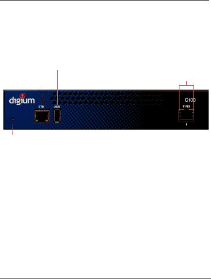
Front Panel Identification
This section describes the components on the front panel of the Gateway Series models.
USB
Recovery
T1/E1
Gigabit Status
Ethernet
Device |
|
|
|
|
|
|
|
|
|
|
|
|
|
|
|
|
|
|
|
|
|
|
|
Status |
Ethernet |
T1/E1 |
|||||
|
Status |
Port |
|||||
Figure 4: G100 Single Port Appliance
Digium, Inc. |
Page 19 |
Chapter 2: Unit Installation
USB
Recovery
T1/E1
Gigabit Status
Ethernet
Device |
|
|
|
|
|
|
|
|
|
|
|
|
|
|
|
|
|
|
|
|
Status |
Ethernet |
T1/E1 |
||||
|
Status |
Port |
||||
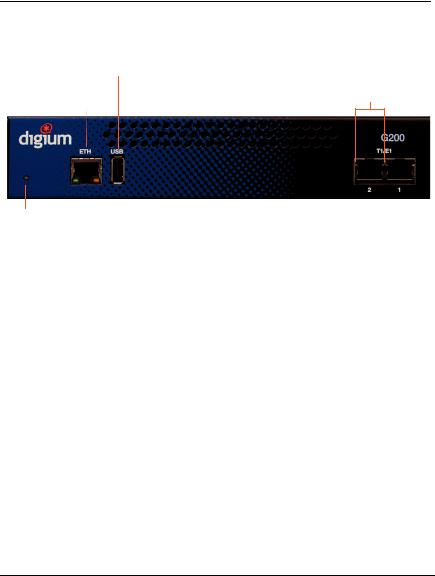
Figure 5: G200 Dual Port Appliance
Digium, Inc. |
Page 20 |
Chapter 2: Unit Installation
|
|
|
USB |
T1/E1 |
|
|
|
|
Recovery |
||
Reset |
Gigabit |
Status |
|||
Ethernet |
|
|
|||
|
|
|
|
||
|
|
|
|
|
|
|
|
|
|
|
|
|
|
|
|
|
|
|
|
|
|
|
|
Device |
|
|
|
|
|
Status |
Ethernet |
T1/E1 |
|||
|
Status |
Port |
|||
|
|
|
|||
Figure 6: G800 Octal Port Appliance
Device Status - This LED corresponds to the status of the Gateway Series appliance. See Frequently Asked Questions on page 80 for more information.
Gigabit Ethernet - The 10/100/1000BaseT Ethernet port(s) provides the ability to connect to an internal or external network using an RJ45 interface and supports Auto-MDIX. It is used to pass Ethernet pack etized voice and web management data between the Gateway Series and the network. See Gigabit Ethernet Port Pinouts on page 85 for more information.
Second Gigabit Ethernet (G400/G800 only) - The second 10/100/ 1000BaseT Ethernet port(s) provides the ability to connect to an inter nal or external network using an RJ45 interface and supports AutoMDIX. It is used to pass Ethernet packetized voice and web manage ment data between the Gateway Series and the network. See Gigabit Ethernet Port Pinouts on page 85 for more information.
Digium, Inc. |
Page 21 |

Chapter 2: Unit Installation
Ethernet Status - These LEDs correspond to the status of the Ethernet connection. See Frequently Asked Questions on page 80 for more information.
USB Recovery - This port can be used to perform a firmware recovery and configuration reset. See Firmware Recovery and Configuration Reset on page 78 for more information.
Warning! The USB Recovery port provides a limited amount of current which is sufficient only to power a USB flash drive. Do not connect any other type of device to this port. The USB flash drive should be fully USB 2.0 compliant.
T1/E1 Port(s) - These ports are used for connecting T1 or E1 cables. See RJ45 T1/E1 Port Connector on page 86 for more information.
T1/E1 Status - These LEDs correspond to the status of the T1/E1 ports. See Frequently Asked Questions on page 80 for more infor mation.
Reset Switch (G400/G800 only) - This recessed switch is used to restart the Gateway Series appliance or reset its GUI password. See
Frequently Asked Questions on page 80 for more information.
Digium, Inc. |
Page 22 |

Chapter 2: Unit Installation
Unit Identification
The defining characteristic of the Gateway Series models are the number of T1/E1 and Ethernet ports supported. See Table 1 for a list of the various models.
Table 1: Gateway Series Models
|
|
|
|
Model |
Type |
T1/E1 Ports |
Ethernet Ports |
|
|
|
|
|
|
|
|
G100 |
T1/E1 |
1 |
1 |
|
|
|
|
G200 |
T1/E1 |
2 |
1 |
|
|
|
|
G400 |
T1/E1 |
4 |
2 |
|
|
|
|
G800 |
T1/E1 |
8 |
2 |
|
|
|
|
Digium, Inc. |
Page 23 |
Chapter 2: Unit Installation
Hardware Installation
This section describes how to properly install the hardware for a Gateway Series appliance.
Caution
Only qualified service personnel should continue with hardware installation and configuration of the Gateway Series appliance. Users should not attempt to perform these functions themselves.
Caution
This equipment is intended for use in Restricted Access Areas only where equipotential bonding has been applied.
Grounding
The Gateway Series appliance must be properly earth grounded for safety reasons. If the unit is not properly earth grounded, the unit and/or other equipment connected to the unit could be damaged. If a Gateway Series appliance is damaged while it is improperly grounded, the warranty on the Gateway Series appliance is void.
A ground lug is located on the opposite side from the front panel of a Gateway Series appliance. Attach an appropriate length and gauge of wire to the double-crimp ground ring terminal. The wire length should be as short as possible, and gauge should be 18 AWG or greater. Stranded or solid wire is acceptable. Wire is not provided with the Gateway Series
Digium, Inc. |
Page 24 |

Chapter 2: Unit Installation
appliance. Double crimp the ground ring terminal to the wire. Next, slide the ground ring terminal over the ground lug. Then fasten the ground ring terminal to the ground lug using the ground nut. The ground nut must be turned clockwise to tighten it onto the ground lug. The opposite end of the wire that is connected to the ground ring terminal should be securily fastened to an unpainted metalic section of a properly earth grounded equipment rack. A connector for the opposite end of the wire is not provided with the Gateway Series appliance.
Note: Taking into consideration the requirements of all equipment connected to or sharing the rack, the equipment rack should be properly earth grounded. Refer to the manufacturer of the rack for instructions on how to properly earth ground the rack.
Important
Use only a grounded electrical outlet when connecting the Gateway Series appliance to a power source. If you do not know whether the outlet is grounded, consult with a qualified electrician.
Digium, Inc. |
Page 25 |
Chapter 2: Unit Installation
Mounting
The included hardware allows the Gateway Series appliance to be wall mounted, rack mounted side-by-side with another Gateway Series appliance, or placed flat on a level surface. If a single Gateway Series appliance is to be rack mounted, the optional long mounting bracket (not supplied, part number 3244-00042) must be used. The optional long mounting bracket can be ordered by contacting a Digium reseller or Digium directly.
Important
Reliable earth grounding of rack-mount equipment should be maintained. Particular attention should be given to provide connection other than direct connections to the branch circuit (e.g., use of power strips).
Important
Mounting of the Gateway Series appliance in a rack should be such that no hazardous condition is achieved due to uneven mechanical loading. Do not place heavy objects on top of the unit, or pull down on the mounted unit. Consider the mechanical loading of external cables. The weight of the cables can pull on the unit and create uneven loading. Secure heavy cables with external cable trays.
Important
If rack mounting, install the Gateway Series appliance in a rack so that the amount of airflow required for safe operation is not compromised.
Digium, Inc. |
Page 26 |

Chapter 2: Unit Installation
Important
If the Gateway Series appliance is installed in a system that is in turn installed in a closed or multi-unit rack assembly, the operating ambient temperature of the rack environment may be significantly greater than the room ambient. While the maximum safe operating temperature is 50°C, consideration should be given to installing the unit in an environment compatible with the maximum recommended ambient temperature of 45°C for long term reliability and maximum performance.
Single Unit Rack Mount:
In order to rack mount the Gateway Series appliance by itself, place one of the short mounting brackets on the front of one side of the Gateway Series appliance. Line up the holes from the mounting bracket to the threaded holes on the front side of the Gateway Series appliance. Two #8 black truss head screws should be inserted and turned clockwise to fasten the mounting bracket. Do not over-tighten. Repeat these steps when installing the optional long mounting bracket (not supplied, part number 3244-00042) on the other side of the Gateway Series appliance. Then use another 2 #8 black truss head screws on each mounting bracket to secure the Gateway Series appliance to a rack.
Digium, Inc. |
Page 27 |

Chapter 2: Unit Installation
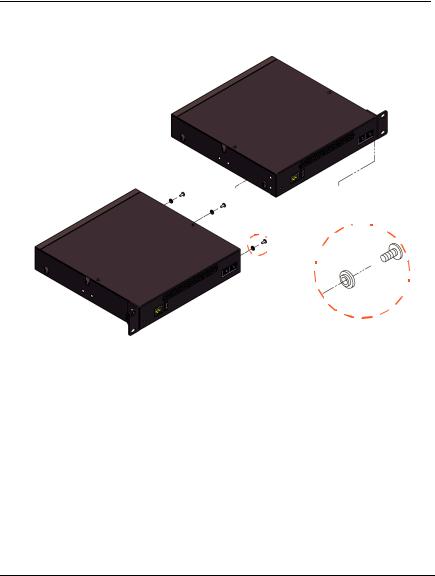
Side-by-side Rack Mount:
In order to rack mount the Gateway Series appliance side-by-side with another Gateway Series appliance, place one of the short mounting brackets on the front of the left side of the first Gateway Series appliance. Line up the holes from the mounting bracket to the threaded holes on the front of the left side of the first Gateway Series appliance. Two #8 black truss head screws should be inserted and turned clockwise to fasten the mounting bracket. Repeat these steps when installing a short mounting bracket on the front of the right side of the second Gateway Series appliance.
Each of the three #6 pan head screws should be inserted into a shoulder washer as shown in Figure 7 on page 29. Make sure the narrow side of the shoulder washer is away from the head of the screw. The three screws should then be inserted and turned clockwise to fasten to the side-by-side holes on the right side of the first Gateway Series appliance. Do not overtighten the screws or the shoulder washers could be damaged. Connect the first and second Gateway Series appliances together by putting the heads of three screws & shoulder washers into the three keyed insets. Then push down on the second Gateway Series appliance as shown in Figure 7. Make sure the units are flat against each other before pushing the second unit down. Otherwise the shoulder washers may be damaged. Use two truss head screws (not supplied) on each mounting bracket to secure both Gateway Series appliances to a rack.
Digium, Inc. |
Page 28 |
Chapter 2: Unit Installation
Figure 7: Side-by-side Rack Mounting
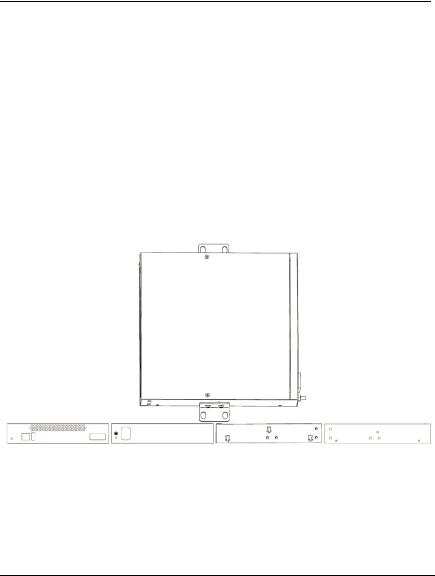
Wall Mount:
In order to wall mount the Gateway Series appliance, the short mounting brackets should be flipped and rotated, and fastened on the middle of the right and left sides of the Gateway Series appliance as shown in Figure 8 on page 30. The unit should be mounted at or below eye level to properly view the LEDs. In addition, the Gateway Series appliance should be properly oriented as shown in Figure 8. Orientations other than what is shown in Figure 8 are not acceptable.
Digium, Inc. |
Page 29 |
Chapter 2: Unit Installation
If the Gateway Series appliance is placed in the “right side down” orientation, the 2 remaining #8 black truss head mounting screws should be fully inserted into the screw holes near the front of the right side of the Gateway Series appliance. In addition, the three #6 pan head screws should be fully inserted into the side-by-side holes on the right side of the first Gateway Series appliance.
Note: The Gateway Series appliance must be properly grounded for safety reasons. If the unit is not properly grounded, damage could arise to the unit and/or other equipment connected to the unit.
Right side down
Front side |
Back side |
Left side |
Right side |
Figure 8: Acceptable Wall Mount Orientation
Digium, Inc. |
Page 30 |
Loading...