


VHF 300 Series Radio Installation Instructions
These installation instructions are for the following VHF radios and handsets:
North American Models |
International Models |
VHF 300 |
VHF 300i |
VHF 300 AIS |
VHF 300i AIS |
GHS™ 10 |
GHS 10i |
Throughout these instructions, both the VHF 300 and the VHF 300i will be referred to as the VHF 300 series radio, or “the radio”. The GHS 10 and the GHS 10i will be referred to as the GHS 10.
Compare the contents of this package with the packing list on the box. If any pieces are missing, contact your Garmin® dealer immediately.
Product Registration
Help us better support you by completing our online registration today. Go to http://my.garmin.com. Keep the original sales receipt, or a photocopy, in a safe place.
Contact Garmin
Contact Garmin Product Support if you have any questions while using your VHF 300 series radio. In the USA, go to www.garmin.com/support, or contact Garmin USA by phone at (913) 397.8200 or (800) 800.1020.
In the UK, contact Garmin (Europe) Ltd. by phone at 0808 2380000.
In Europe, go to www.garmin.com/support and click Contact Support for in-country support information, or contact Garmin (Europe) Ltd. by phone at +44 (0) 870.8501241.
Warnings and Safety Notices
Antenna Mounting and EME Exposure
The VHF 300 series radio generates and radiates radio frequency (RF) electromagnetic energy (EME). Failure to observe these guidelines may expose persons to RF radiation absorption exceeding the maximum permissible exposure (MPE).
Garmin declares an MPE radius of 59 in. (1.5 m) for this system, which was determined using 25 watts output to an omni-directional 9 dBi gain antenna. The antenna should be installed such that a distance of 59 in. (1.5 m) is maintained between the antenna and all persons.
WARNING: Radio operators with cardiac pacemakers, life-support machines, or electrical medical equipment should not be exposed to excessive radio-frequency fields.
 warning: Operate the device in accordance with the instructions supplied.
 Caution: Wear safety goggles and a dust mask when drilling, cutting, or sanding.
 notice: The device complies with internationally recognized standards covering human exposure to electromagnetic fields from radio devices.
 notice: Check with local authorities for any antenna or operational restrictions that may apply.
Notice: To prevent possible damage to your radio, the antenna must be connected to the radio before transmitting. This ensures that the power output to the antenna port dissipates properly when transmitting.
Needed Tools
•Drill and drill bits
•#2 Phillips screwdriver
•3 1/2 in. (90 mm) hole saw (for installing the active speaker)
•Waterproof, adhesive tape (such as rubber vulcanizing tape)
May 2010 |
190-01098-02 Rev. C |
Printed in China |

Installing your VHF 300 Series Radio
1.Select locations for the radio components.
2.Install the transceiver box (page 3).
3.Install the active speaker (page 4).
4.Install the GHS 10 (page 5).
Although these options are not necessary to use your radio, these instructions cover the following additional installation options.
•Connecting the GHS 10 to a passive speaker (page 5)
•Connecting the radio to a chartplotter or another GPS device (page 5)
•Connecting the radio to a hailer horn (page 7).
Selecting Locations for the VHF 300 Series Radio Components
Use the diagram to determine how to best organize the VHF 300 series radio components on your boat. Test to be sure the cables reach all components before permanently mounting any component.
Antenna connector 
GHS 10 station 1 |
|
|
This GHS 10 must |
|
|
be located in the |
|
|
wheelhouse or an |
VHF 300 transceiver box |
|
adjacent room per |
||
|
||
FCC law. |
|
GHS 10 cable |
NMEA 2000 drop |
extension |
cable (optional) |
(optional) |
|
|
VHF 300 power/data cable |
NMEA 2000 network (optional)
NMEA 0183 device (optional)
Hailer horn (optional)
|
|
Clip and tape |
10 A |
|
|
fuse |
|
|
|
bare wires |
Switch |
|
GHS 10 |
|
12 Vdc |
Passive |
cable |
|
|
speaker |
|
|
|
(not included) |
Active |
GHS 10 active |
|
speaker |
|
||
|
cable |
speaker |
|
|
Bulkhead pass-through |
|
GHS 10 |
plate |
GHS 10 |
|
GHS 10 with a passive speaker |
GHS 10 with an active speaker |
|
|
|
VHF 300 Series Layout Diagram |
Notes:
• Install the transceiver box in a dry, protected location.
|
VHF 300 Series Installation Instructions |
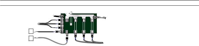
•Connect the transceiver box to a 12 Vdc battery through an accessible switch.
•Install the GHS 10 connected to station one on the transceiver box in the wheelhouse or an adjacent room per Federal Communications Commission (FCC) law.
•Ensure that you install each component of the VHF radio at least 20 in. (.5 m) from any compass. Test your compass to verify that it operates correctly when the radio is operating.
•Extension cables are available for the GHS 10 cable.
Installing the Transceiver Box
Install the transceiver box below deck on a bulkhead, in a location that is dry and protected from washdown. Ensure that the location is well ventilated and away from objects that generate heat. Ensure that the transceiver box is at least 20 in. (.5 m) from any compass to avoid interference.
Mounting the Transceiver Box
1.Ensure that the chosen location is dry, protected, and well-ventilated.
2.Use the template on page 11 to determine mounting holes.
3.Drill four 1/8 in. (3 mm) pilot holes.*
4.Mount the transceiver box using the included M4.2×25 screws. You can also use bolts, washers, and nuts (not included) to mount the transceiver box if the mounting surface allows.
Connecting the Transceiver Box to Power
Use the VHF 300 power/data cable to connect the transceiver box to a 12 Vdc battery through an external switch.
Notes:
• Use the VHF 300 Power Wiring-Assignment Table to identify the positive and negative wires.
•The replacement fuse on the power/data wiring harness is a 10 A, slow-blow fuse.
•If it is necessary to extend the power wires, use at least 16 AWG wire.
•If your boat has an electrical system, you might be able to wire the radio directly to an unused holder on your fuse block. If you use the fuse block, remove the in-line fuse holder supplied with the power/data cable.
Device |
Wire Color |
Function |
|
VHF 300 power/data |
Red |
Power—positive (+) |
|
cable |
|
|
|
Black |
Ground—negative (-) |
||
|
VHF 300 Power Wiring-Assignment Table
 Notice: Cover the connections with a waterproof, adhesive tape, such as rubber vulcanizing tape, to prevent water from seeping into the radio.
|
|
- |
|
+ |
|
+– |
|
|
|
|
|
Boat ground 10 A fuse
To 10.8-15.6 Vdc boat supply To VHF 300 power/data cable
Wiring the VHF 300 Through a Fuse Block
Connecting an Antenna to the Transceiver Box:
1.Mount the antenna on your boat according the instructions provided by the antenna manufacturer.
2.Connect the antenna to the antenna port on the transceiver box.
NOTE: The antenna port is on the opposite side of the transceiver box from the primary row of connectors pictured on page 4.
* A 1/8 in. (3 mm) pilot hole is nominal for plywood. Different dashboard materials my require a different size pilot hole.
VHF 300 Series Installation Instructions
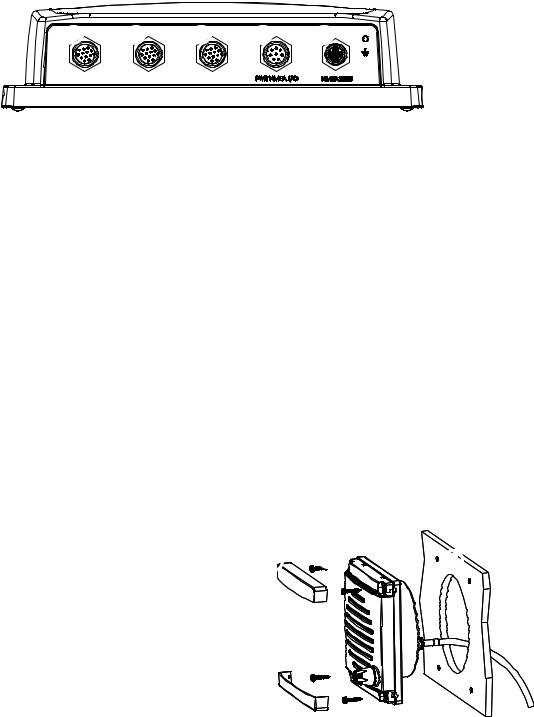
Identifying the VHF 300 Transceiver Box Connectors
Use the illustration to identify the connectors on the VHF 300 transceiver box.
VHF 300 Transceiver Box Connectors
GHS 10 expansion connector
HS-1—primary GHS 10 connector
the wheelhouse GHS 10 must connect to this port
VHF 300 power/data cable connector NMEA 2000 connector (optional) Antenna port (on back - not pictured)
Installing the GHS 10 and Speaker
The GHS 10 connects to the transceiver box and to either the Garmin GHS 10 active speaker (included) or a passive speaker (not included). When planning the GHS 10 installation, consider the following:
•Per FCC law, you must install the GHS 10 in the wheelhouse or an adjacent room.
•Install the GHS 10 and the active speaker at least 20 in. (.5 m) from any compass.
•Install the active speaker within 48 in. (1.2 m) of the location you mount the bulkhead pass-through plate.
•Consult the VHF 300 Series Layout Diagram on page 2 to determine how to connect the GHS 10 through a bulkhead to a speaker and to the transceiver box.
•If the cable is not long enough to reach the GHS 10 mounting location from the transceiver box, extension cables are available in lengths of 16 ft. (5 m) and 32 ft. (10 m). Install any extensions between the GHS 10 cable and the transceiver box according to the layout diagram on page 2.
•When you install the GHS 10 active speaker, if you use the GHS 10 cable to connect the active speaker to the transceiver box, do not connect a passive speaker to the GHS 10 cable. Clip and tape the passive speaker wires.
Installing the GHS 10 Active Speaker
1.Use the GHS 10 active speaker Flush Mount Template to mount the active speaker. The template is self-adhesive.
2.Remove the paper backing from the template and adhere it to the bulkhead in a suitable location.
3.Use a 3 1/2 in. (90 mm) hole saw to cut the opening as indicated on the template.
4.Place the speaker in the cutout.
5.Ensure that the mounting screw locations align with mark the locations of new pilot holes. 
6.Drill four 1/8 in. (3 mm) pilot holes* in the correct location.
7.Use the included M4.2×25 screws to mount the active speaker.
8.Snap the cover plates on the active speaker.
9.To install the active speaker wiring harness to the transceiver box, use the GHC 10 cable according to the layout diagram on page 2.
Cover plates (×2)M4.2×25 screws (×4)Active speaker
Bulkhead
Mounting the Active Speaker
•Do not connect a passive speaker to the GHC 10
cable you use with the active speaker. Clip and tape the two passive speaker wires.
•If the GHC 10 cable is not long enough to reach the transceiver box location, install an extension (not included) between the GHC 10 cable and the transceiver box as shown on the layout diagram on page 2.
10.To install the active speaker wiring harness though the bulkhead, follow the procedures on page 5.
* A 1/8 in. (3 mm) pilot hole is nominal for plywood. Different dashboard materials my require a different size pilot hole.
|
VHF 300 Series Installation Instructions |
 Loading...