


 Loading...
Garmin echoMAP 73sv, echoMAP 74dv, echoMAP 74sv, echoMAP 75sv, echoMAP 91sv Installation Instructions
...Transom-Mount Transducer Installation Instructions......................................................................... |
2 |
Instructions d'installation de la sonde avec montage sur tableau arrière........................................... |
5 |
Istruzioni di installazione del trasduttore di poppa............................................................................. |
8 |
Schwinger für die Heckspiegelmontage – Installationsanweisungen.............................................. |
11 |
Instrucciones de instalación del transductor de montaje en espejo de popa................................... |
14 |
Instruções de instalação do transdutor com suporte para painel de popa...................................... |
17 |
Installatie-instructies voor transducer met spiegelmontage............................................................. |
20 |
Installationsvejledning til agterspejlsmonteret transducer................................................................ |
23 |
Peräpeiliin kiinnitettävän kaikuanturin asennusohjeet..................................................................... |
26 |
Installeringsinstruksjoner for hekkmontert svinger........................................................................... |
29 |
Akterspegelmonterad givare – installationsinstruktioner.................................................................. |
32 |
Instrukcja instalacji przetwornika na pawęży................................................................................... |
35 |
Pokyny pro instalaci sonarové sondy připevněné k záďové stěně.................................................. |
38 |
Upute za montažu sonde na krmenom zrcalu................................................................................. |
41 |
.............................................................................................................. |
44 |
Garmin® and the Garmin logo are trademarks of Garmin Ltd. or its subsidiaries, registered in the USA and other countries. These trademarks may not be used without the express permission of Garmin.
November 2014 |
Printed in Taiwan |
190-01850-87_0A |
Transom-Mount Transducer
Installation Instructions
To obtain the best performance and to avoid damage to your boat, you must install the Garmin® transducer according to these instructions.
Read all installation instructions before proceeding with the installation. If you experience difficulty during the installation, contact Garmin Product Support.
Registering Your Device
Help us better support you by completing our online registration today.
•Go to http://my.garmin.com.
•Keep the original sales receipt, or a photocopy, in a safe place.
Contacting Garmin Product Support
•Go to www.garmin.com/support for in-country support information.
•In the USA, call 913-397-8200 or 1-800-800-1020.
•In the UK, call 0808 238 0000.
•In Europe, call +44 (0) 870 850 1241.
Important Safety Information
 WARNING
See the Important Safety and Product Information guide in the product box for product warnings and other important information.
You are responsible for the safe and prudent operation of your vessel. Sonar is a tool that enhances your awareness of the water beneath your boat. It does not relieve you of the responsibility of observing the water around your boat as you navigate.
 CAUTION
Failure to install and maintain this equipment in accordance with these instructions could result in damage or injury.
Always wear safety goggles, ear protection, and a dust mask when drilling, cutting, or sanding.
NOTICE
When drilling or cutting, always check what is on the opposite side of the surface.
This equipment must be installed by a qualified marine installer.
Loading the New Software on a Memory Card
You must copy the software update to a memory card.
1 Insert a memory card into the card slot on the computer. 2 Go to www.garmin.com/support/software/marine.html.
3Select Download next to “Garmin Marine Network with SD card”.
4 Read and agree to the terms.
5 Select Download.
6 If necessary, select Run or save and open the file.
7If necessary, select the drive associated with the memory card, and select Next > Finish.
Updating the Device Software
Before you can update the software, you must obtain a software-update memory card or load the latest software onto a memory card.
1 Turn on the chartplotter.
2After the home screen appears, insert the memory card into the card slot.
NOTE: In order for the software update instructions to appear, the device must be fully booted before the card is inserted.
3 Follow the on-screen instructions.
4Wait several minutes while the software update process completes.
The device returns to normal operation after the software update process is complete.
5Remove the memory card.
NOTE: If the memory card is removed before the device restarts fully, the software update is not complete.
Tools Needed
•Drill and drill bits
•Two 13 mm hex wrenches
•Number 2 Phillips screwdriver
•Masking tape
•Marine sealant
About the Transducer
The transducer transmits and receives sound waves through the water, and relays sound-wave information to your Garmin sonar device.
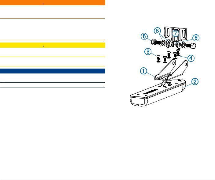
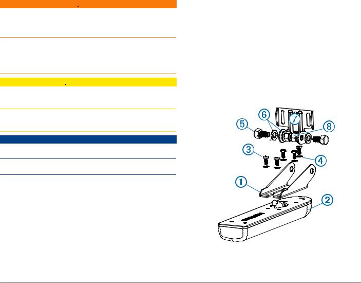
Assembling the Transducer
1 Attach the mount to the transducer with the included
À Á
8 mm M4 screws , and 4 mm star washers .
 Ã
2 Attach the mount to the bracket with the included 16 mm
Æ
M8 screws , M8 flat washers , and M8 lock nuts .
Ä Å Ç
Installing the Transducer on a Transom
Mounting Location Considerations
•The transducer should be mounted as close to the center of the boat as possible.
•The transducer should not be mounted behind strakes, struts, fittings, water intake or discharge ports, or anything that creates air bubbles or causes the water to become turbulent.
The transducer must be in clean (non-turbulent) water for optimal performance.
•The transducer should not be mounted in a location where it might be jarred when launching, hauling, or storing.
2

•On single-drive boats, the transducer must not be mounted in the path of the propeller.
The transducer can cause cavitation that can degrade the performance of the boat and damage the propeller.
•On twin-drive boats, the transducer should be mounted between the drives, if possible.
Installing the Transom-Mount Hardware
NOTICE
If you are mounting the bracket on fiberglass with screws, it is recommended to use a countersink bit to drill a clearance counterbore through only the top gel-coat layer. This will help to avoid any cracking in the gel-coat layer when the screws are tightened.
The cables connected to the transducer should not be cut, because cutting the transducer cables voids your warranty.
1 Position the transducer mount so the center of the bottom
À
of the transducer is level with the bottom edge of the transom and is parallel to the water line.
2 Align the transducer parallel to the water line , and mark the
Á
center location of the two outer holes and the center hole of the transducer mount.
3Wrap a piece of tape around a 4 mm (5/32 in.) bit at 15 mm (19/32 in.) from the point of the bit, to avoid drilling the pilot holes too deep.
4If you are installing the bracket on fiberglass, place a piece of tape over the pilot-hole location to reduce cracking of the gel coat.
5Using the 4 mm (5/32 in.) bit, drill the pilot holes approximately 15 mm (19/32 in.) deep at the marked locations.
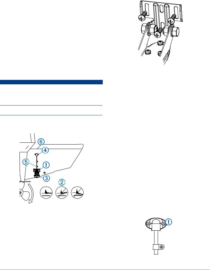
6Apply marine sealant to the included 20 mm screws, and attach the transducer assembly to the transom.
NOTE: A third screw in the lower center screw hole stabilizes the mount.
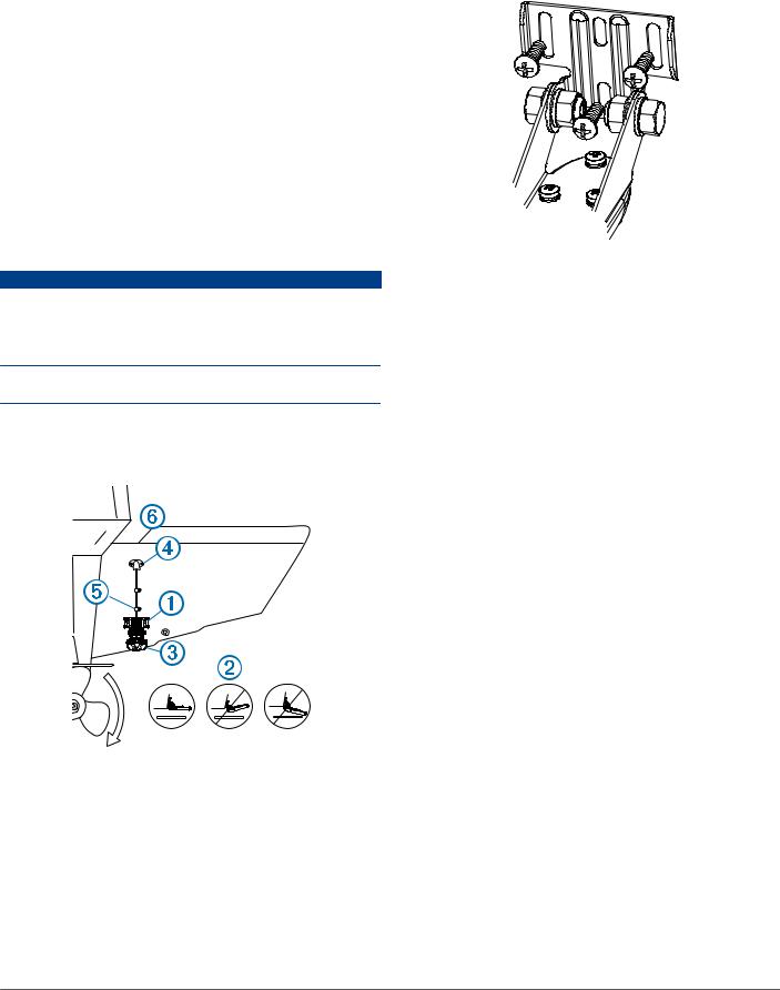
7 |
If you must route the cable through the transom, choose a |
|
pilot-hole location well above the waterline à and mark it. |
8 |
Place a cable clamp on the transducer cable Ä, |
|
approximately one third of the distance between the |
transducer and the top of the transom or the pilot hole.
9 Mark the pilot-hole location for the cable clamp, and using a 3.2 mm (1/8 in.) bit, drill a pilot hole approximately 10 mm (3/8 in.) deep.
10Apply marine sealant to the included 12 mm screw, and attach the cable clamp to the transom.
11Repeat steps 10–12 to install the other cable clamp approximately two thirds of the distance between the transducer and the top of the transom or the pilot hole.
12If you marked a pilot hole in step 9, use a 25 mm (1 in.) drill bit to drill a pass-through hole completely through the transom.
13Route the transducer cable to the sounder:
•If you are routing the cable using a pass-through hole, feed it through the hole you drilled in step 14, and install
the cable-entry cover .
Ã
• If you are not routing the cable using a pass-through hole, route the cable up and over the top of the transom .
Å
Avoid routing the cable close to electrical wires or other sources of electrical interference.
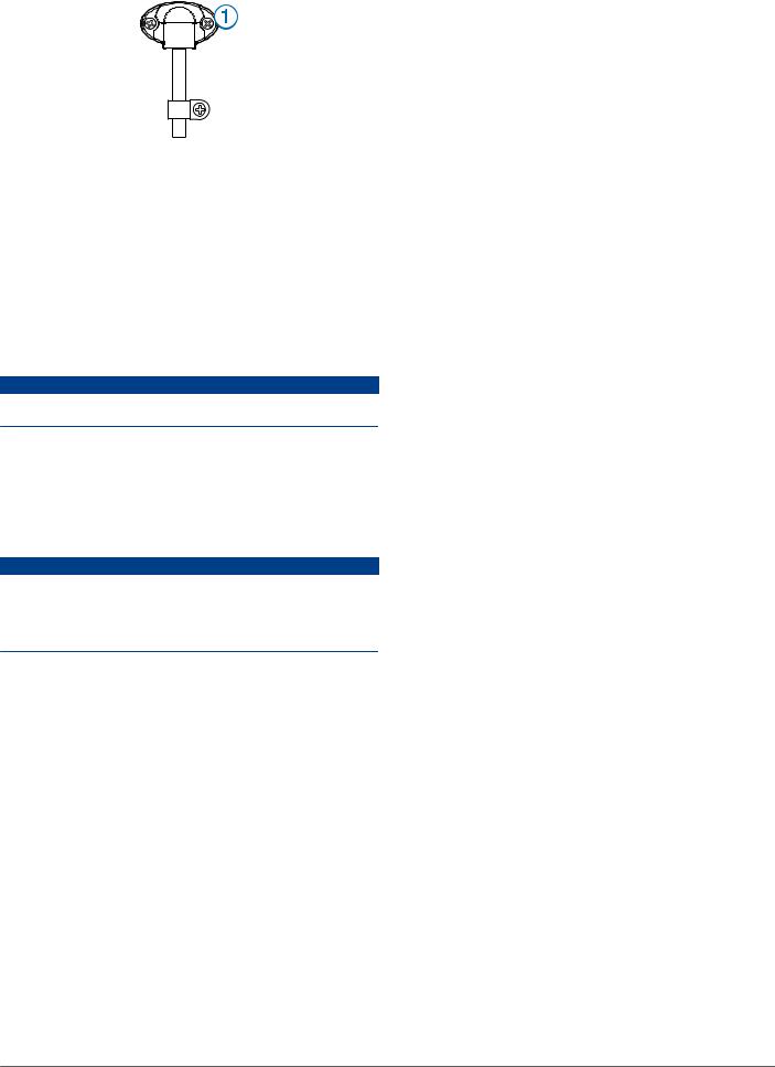
Installing the Cable-Entry Cover
If you routed the cable through the transom after you installed the transducer, you should install the cable-entry cover to keep water from entering your boat.
1 Place the cable-entry cover over the hole and the cable,
À
with the opening pointing downward, and mark the location of the two pilot holes.
2Remove the cable-entry cover, and, using a 3.2 mm (1/8 in.) bit, drill the pilot holes approximately 10 mm (3/8 in.) deep.
3Fill the pass-through hole with marine sealant so it covers the cable completely and there is excess sealant around the hole and the cable.
4Place the cable-entry cover over the hole and the cable, with the opening pointing downward.
3

5Apply marine sealant to the included 12 mm M4 screws, and attach the cable-entry cover to the transom.
6 Wipe away all excess marine sealant.
Testing the Installation
NOTICE
You should check your boat for leaks before you leave it in the water for an extended period of time.
Because water is necessary to carry the sonar signal, the transducer must be in the water to work properly. You cannot get a depth or distance reading when out of the water. When you place your boat in the water, check for leaks around any screw holes that were added below the water line.
Testing the Transom-Mount Transducer Installation
NOTICE
When adjusting the depth of the transducer, make the adjustments in small increments. Placing the transducer too deep can adversely affect the performance of the boat and put the transducer at risk of striking underwater objects.
Test the transom-mount transducer installation in open water free of obstacles. Pay attention to your surroundings as you test the transducer.
1 With the boat in the water, turn on the chartplotter.
2Drive the boat at a slow speed. If the chartplotter appears to be working properly, gradually increase speed while observing the chartplotter.
3If the sonar signal is suddenly lost or the bottom return is severely degraded, note the speed at which this occurs.
4Return the boat to the speed at which the signal was lost, and make moderate turns in both directions while observing the chartplotter.
5If the signal strength improves while turning, adjust the transducer so that it extends another 1/8 in. (3 mm) below the transom of the boat.
6 Repeat steps 2–4 until the degradation is eliminated.
7If the signal does not improve, move the transducer to a different location on the transom, and repeat the test.
4
Instructions d'installation de la sonde avec montage sur tableau arrière
Pour obtenir des performances optimales et éviter toute détérioration du bateau, installez la sonde Garmin selon les instructions suivantes.
Lisez toutes les instructions d'installation avant de procéder à l'installation. Si vous rencontrez des difficultés durant l'installation, contactez le service d'assistance produit de Garmin.
Enregistrement de l'appareil
Aidez-nous à mieux vous servir en remplissant dès aujourd'hui notre formulaire d'enregistrement en ligne.
•Rendez-vous sur le site http://my.garmin.com.
•Conservez en lieu sûr l'original de la facture ou une photocopie.
Contacter l'assistance produit Garmin
•Rendez-vous sur le site www.garmin.com/support pour obtenir une assistance par pays.
•Aux Etats-Unis, appelez le 913-397-8200 ou le 1-800-800-1020.
•Au Royaume-Uni, appelez le 0808 238 0000.
•En Europe, appelez le +44 (0) 870 850 1241.
Informations importantes relatives à la sécurité
 AVERTISSEMENT
Consultez le guide Informations importantes sur le produit et la sécurité inclus dans l'emballage du produit pour prendre connaissance des avertissements et autres informations importantes sur le produit.
Vous êtes responsable de l'utilisation sûre et prudente de votre bateau. Le sondeur est un outil qui vous permet de connaître la hauteur d'eau en dessous de votre bateau. Il ne vous dégage pas de votre responsabilité d'observation pendant la navigation.
 ATTENTION
Le non-respect de ces instructions lors de l'installation ou de l'utilisation de cet équipement peut provoquer des dommages ou des blessures.
Portez toujours des lunettes de protection, un équipement antibruit et un masque anti-poussière lorsque vous percez, coupez ou poncez.
AVIS
Lorsque vous percez ou coupez, commencez toujours par vérifier la nature de la face opposée de l'élément.
Cet équipement doit être installé par un électronicien qualifié pour l'installation de produits marine.
Chargement du nouveau logiciel sur une carte mémoire
Vous devez copier la mise à jour du logiciel sur une carte mémoire.
1Insérez une carte mémoire dans le lecteur de carte SD de l'ordinateur.
2 Visitez le site www.garmin.com/support/software/marine.html.
3Sélectionnez Télécharger en regard de « Garmin Marine Network with SD card ».
4 Lisez et approuvez les conditions.
5 Sélectionnez Télécharger.
6Si besoin, sélectionnez Exécuter ou enregistrez et ouvrez le fichier.
7Si besoin, sélectionnez le lecteur associé à la carte mémoire puis sélectionnez Suivant > Terminer.
Mise à jour du logiciel de l'appareil
Afin de pouvoir mettre à jour le logiciel, vous devez vous procurer une carte mémoire de mise à jour logicielle ou charger la dernière version du logiciel sur une carte mémoire.
1 Mettez le traceur sous tension.
2Lorsque l'écran d'accueil apparaît, insérez la carte mémoire dans le lecteur de carte mémoire.
REMARQUE : pour que les instructions de mise à jour du logiciel apparaissent, l'appareil doit avoir été complètement démarré avant que la carte ne soit insérée.
3 Suivez les instructions présentées à l'écran.
4Patientez quelques minutes le temps que la procédure de mise à jour du logiciel s'exécute.
L'appareil reprend son fonctionnement normal lorsque le processus de mise à jour du logiciel est terminé.
5Retirez la carte mémoire.
REMARQUE : si la carte mémoire est retirée avant que l'appareil ne redémarre complètement, la mise à jour du logiciel n'est pas terminée.
Outils requis
•Perceuse et forets
•Deux clés hexagonales de 13 mm
•Tournevis cruciforme numéro 2
•Ruban adhésif de protection
•Mastic d'étanchéité
A propos de la sonde
La sonde transmet et reçoit des ondes sonores à travers l'eau puis communique ces informations à votre sondeur Garmin.
Assemblage de la sonde
1 Fixez le support à la sonde avec les vis 8 mm M4 et
À Á Â les rondelles éventail 4 mm fournies.
Ã
2 Fixez le support au support de montage avec les vis
Æ
16 mm M8 , les rondelles plates M8 et les contre-écrous
Ä Å
M8 fournis .
Ç
5
Installation de la sonde sur tableau arrière
Remarques relatives à l'emplacement de montage
•Vous devez monter la sonde aussi près que possible du centre du bateau.
•L'emplacement de la sonde ne doit pas se trouver derrière des virures, haubans, appareillages, une prise d'eau, des orifices de refoulement ou tout autre élément susceptible de créer des bulles d'air ou de causer des turbulences dans l'eau.
Pour obtenir des performances optimales, la sonde doit être placée en eau calme (non turbulente).
•Ne montez pas la sonde dans un emplacement où elle pourrait être secouée en cas de mise à l'eau, de chargement ou de stockage.
•Sur les bateaux monomotorisés, la sonde ne doit pas être montée dans le sillage de l'hélice.
La sonde peut provoquer des cavitations, pouvant dégrader les performances du bateau et endommager l'hélice.
•Sur les bateaux bimotorisés, la sonde doit être montée entre les systèmes d'entraînement, si possible.
Installation du kit de montage sur tableau arrière
AVIS
Si vous montez le support de montage sur de la fibre de verre avec des vis, nous vous recommandons d'utiliser un foret de fraisage pour percer un trou à fond plat à travers le revêtement de la couche supérieure. De cette manière, vous ne risquez pas de fissurer le revêtement au moment du serrage des vis.
Les câbles connectés à la sonde ne doivent pas être coupés, car ceci annule votre garantie.
1 Placez le support de la sonde de sorte que le centre du
À
bas de la sonde soit à la même hauteur que le bord inférieur du tableau arrière et parallèle à la ligne de flottaison.
2 Placez la sonde parallèlement à la ligne de flottaison , puis
Á
marquez les emplacements centraux des deux trous externes et du trou central sur le support de la sonde.
3Enroulez un morceau d'adhésif autour de la mèche de 4 mm (5/32 po) à 15 mm (19/32 po) de la pointe de la mèche pour vous servir de repère.
4Si vous installez le support de montage sur de la fibre de verre, collez un morceau d'adhésif sur l'emplacement des trous d'implantation afin de réduire les risques de fissure du revêtement.
5A l'aide du foret de 4 mm (5/32 po), percez les trous d'implantation à environ 15 mm de profondeur (19/32 po), aux emplacements marqués.
6Appliquez un mastic d'étanchéité sur les vis 20 mm fournies, puis fixez la sonde au tableau arrière.
REMARQUE : une troisième vis dans le trou central inférieur vient stabiliser le support.
7Si vous devez faire passer le câble à travers le tableau arrière, choisissez un emplacement de trou d'implantation
largement au-dessus de la ligne de flottaison , puis
Ã
marquez-le.
8 Placez un collier de serrage sur le câble de sonde à
Ä
environ un tiers de la distance entre la sonde et le haut du tableau arrière ou le trou d'implantation.
9Marquez l'emplacement du trou d'implantation du collier de serrage et, à l'aide d'un foret de 3,2 mm (1/8 po), percez un trou d'implantation d'environ 10 mm (3/8 po) de profondeur.
10Appliquez un mastic d'étanchéité sur la vis 12 mm fournie, puis fixez le collier de serrage au tableau arrière.
11Répétez les étapes 10 à 12 pour installer l'autre collier de serrage à environ deux tiers de la distance entre la sonde et le haut du tableau arrière ou le trou d'implantation.
12Si vous avez marqué un trou d'implantation à l'étape 9, utilisez une mèche de 25 mm (1 po) pour percer un trou de passage à travers le tableau arrière.
13Acheminez le câble de sonde vers le sondeur :
•Si vous acheminez le câble à l'aide d'un trou de passage, faites-le passer par l'ouverture que vous avez percée à
l'étape 14, puis installez le passe-fil .
Ã
• Si vous n'acheminez pas le câble à l'aide d'un trou de passage, faites-le passer par dessus le tableau arrière .
Å
Evitez d'approcher le câble de câbles électriques ou de toute autre source d'interférence électrique.
Installation du passe-fil
Si vous avez fait passer le câble à travers le tableau arrière après avoir installé la sonde, vous devez installer le passe-fil pour empêcher l'eau de pénétrer dans votre bateau.
1 Placez le capot d'entrée du câble au-dessus du trou et du
À
câble, orientez l'ouverture vers le bas, puis marquez l'emplacement des deux trous d'implantation.
6

2Retirez le passe-fil et, à l'aide d'une mèche de 3,2 mm (1/8 po), percez les trous d'implantation à environ 10 mm (3/8 po) de profondeur.
3Colmatez le trou de passage avec du mastic d'étanchéité jusqu'à ce que le câble soit entièrement recouvert. Un excédent de mastic doit se trouver sur le pourtour du trou et sur le câble.
4Placez le passe-fil au-dessus du trou et du câble et orientez l'ouverture vers le bas.
5Appliquez un mastic d'étanchéité sur les vis M4 12 mm, puis fixez le passe-fil au tableau arrière.
6 Essuyez tout le résidu de mastic d'étanchéité.
Test de l'installation
AVIS
Il est recommandé de contrôler l'état de votre bateau et la présence éventuelle de fuites quand vous le laissez à quai pendant une période prolongée.
Comme l'eau est indispensable pour transporter le signal du sondeur, la sonde doit se trouver dans l'eau pour fonctionner correctement. Il est impossible d'obtenir des données de profondeur ou de distance si la sonde n'est pas immergée. Lorsque vous mettez votre bateau à l'eau, vérifiez qu'il n'y a pas de fuite autour des vis ajoutées sous la ligne de flottaison.
Test de l'installation de la sonde sur tableau arrière
AVIS
Lorsque vous réglez la profondeur de la sonde, procédez pas à pas. Si vous placez la sonde trop profondément, les performances du bateau pourraient en être affectées et la sonde risquerait de heurter des objets immergés.
Testez l'installation de la sonde sur tableau arrière dans des eaux calmes et dégagées. Tenez compte de votre environnement lors du test de la sonde.
1Lorsque votre bateau est à l'eau, mettez le traceur sous tension.
2Naviguez à vitesse réduite. Si le traceur semble fonctionner correctement, augmentez graduellement la vitesse tout en observant le traceur.
3Si le signal du sondeur est soudain perdu ou si les données de fond renvoyées se dégradent sévèrement, notez la vitesse à laquelle ces problèmes sont survenus.
4Revenez à la vitesse à laquelle le signal a été perdu, et tournez modérément dans l'une et l'autre direction tout en observant le traceur.
5Si la force du signal s'améliore à mesure que vous tournez, réglez la sonde afin qu'elle dépasse de 3 mm (1/8 po) supplémentaires sous le tableau arrière du bateau.
6Répétez les étapes 2 à 4 jusqu'à ce que la perte de signal soit résolue.
7Si le signal ne s'améliore pas, déplacez la sonde à un autre endroit du tableau arrière et répétez le test.
7
Istruzioni di installazione del trasduttore di poppa
Per ottenere le massime prestazioni ed evitare danni all'imbarcazione, installare il trasduttore Garmin attenendosi alle istruzioni riportate di seguito.
Prima di procedere all'installazione, leggere attentamente le istruzioni. In caso di difficoltà durante l'installazione, contattare il servizio di assistenza ai prodotti di Garmin.
Registrazione del dispositivo
Per un'assistenza completa, eseguire subito la registrazione online.
•Visitare il sito Web http://my.garmin.com.
•Conservare in un luogo sicuro la ricevuta di acquisto originale o una fotocopia.
Contattare il servizio di assistenza Garmin
•Per informazioni sull'assistenza nel Paese di residenza, visitare il sito Web www.garmin.com/support.
•Negli Stati Uniti, chiamare il numero 913-397-8200 o 1-800-800-1020.
•Nel Regno Unito, chiamare il numero 0808 238 0000.
•In Europa, chiamare il numero +44 (0) 870 850 1241.
Informazioni importanti sulla sicurezza
 ATTENZIONE
Per avvisi sul prodotto e altre informazioni importanti, consultare la guida Informazioni importanti sulla sicurezza e sul prodotto inclusa nella confezione.
Ogni utente è responsabile della navigazione sicura della propria imbarcazione. L'ecoscandaglio è uno strumento che consente all'utente di conoscere meglio le condizioni del fondale al di sotto dell'imbarcazione, ma non lo esime dalla responsabilità di osservare le condizioni dell'acqua intorno all'imbarcazione durante la navigazione.
 AVVISO
L'installazione e la manutenzione di questa apparecchiatura effettuate non in conformità a queste istruzioni possono causare danni o lesioni.
Durante le operazioni di foratura, taglio o carteggiatura, indossare degli occhiali protettivi, una maschera antipolvere e un'adeguata protezione per l'udito.
AVVERTENZA
Prima di effettuare fori o tagli verificare l'eventuale presenza di oggetti nel lato opposto della superficie da tagliare.
Questa apparecchiatura deve essere installata da un installatore di componenti nautici qualificato.
Caricamento del nuovo software su una scheda di memoria
È necessario copiare l'aggiornamento software su una scheda di memoria.
1Inserire una scheda di memoria nel relativo alloggiamento sul computer.
2Visitare il sito Web www.garmin.com/support/software/marine
.html.
3Selezionare Download accanto a "Garmin Marine Network con scheda SD".
4 Leggere e accettare i termini.
5 Selezionare Download.
6 Se necessario, selezionare Corsa o salvare e aprire il file.
7Se necessario, selezionare l'unità associata alla scheda di memoria, quindi selezionare Successivo > Fine.
Aggiornamento del software del dispositivo
Per poter aggiornare il software, è necessario ottenere una scheda di memoria per l'aggiornamento software o caricare il software aggiornato su una scheda di memoria.
1 Accendere il chartplotter.
2Una volta visualizzata la schermata principale, inserire la cartuccia d'aggiornamento del lettore cartografico.
NOTA: per poter visualizzare le istruzioni di aggiornamento del software, è necessario avviare il dispositivo completamente prima di inserire la scheda.
3 Seguire le istruzioni visualizzate sullo schermo.
4Attendere qualche minuto che il processo di aggiornamento software sia completato.
Il dispositivo torna al normale funzionamento una volta completato il processo di aggiornamento software.
5Rimuovere la scheda di memoria.
NOTA: se la cartuccia d'aggiornamento viene rimossa prima del riavvio completo del dispositivo, l'aggiornamento software non viene completato.
Strumenti necessari per l'installazione
•Trapano e punte da trapano
•Due chiavi esagonali da 13 mm
•Cacciavite Phillips numero 2
•Nastro adesivo di carta
•Sigillante marino
Info sul trasduttore
Il trasduttore trasmette e riceve le onde sonore nell'acqua per poi fornire le informazioni all'ecoscandaglio Garmin.
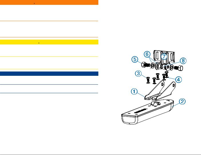
Assemblaggio del trasduttore
1 Collegare il supporto al trasduttore con le viti M4 da
ÀÁ
8 mm incluse e le rondelle a stella da 4 mm .
 Ã
2 Collegare il supporto alla staffa con le viti M8 da 16 mm
Æ
incluse , le rondelle a testa piatta M8 e i dadi di blocco
Ä Å
M8 .
Ç
8
Installazione del trasduttore su uno specchio di poppa
6Applicare del sigillante marino alle viti da 20 mm in dotazione, quindi fissare il gruppo del trasduttore allo specchio di poppa.
Note sulla posizione di installazione |
NOTA: una terza vite nel foro centrale inferiore stabilizza il |
• Installare il trasduttore il più vicino possibile al centro |
supporto. |
dell'imbarcazione. |
|
•Non installare il trasduttore in linea con prese a mare, pattini o qualsiasi altro elemento di disturbo che possa generare bolle d'aria.
Per prestazioni ottimali, il trasduttore deve essere posizionato in acqua pulita (non mossa).
•Non installare il trasduttore in posizioni in cui potrebbe subire degli urti durante le manovre in banchina o in navigazione.
•Sulle imbarcazioni monomotore, non installare il trasduttore a ridosso dell'elica.
Il trasduttore può causare la formazione di cavità che potrebbero compromettere le prestazioni dell'imbarcazione e danneggiare l'elica.
•Sulle imbarcazioni bimotore, se possibile, installare il trasduttore tra i due motori.
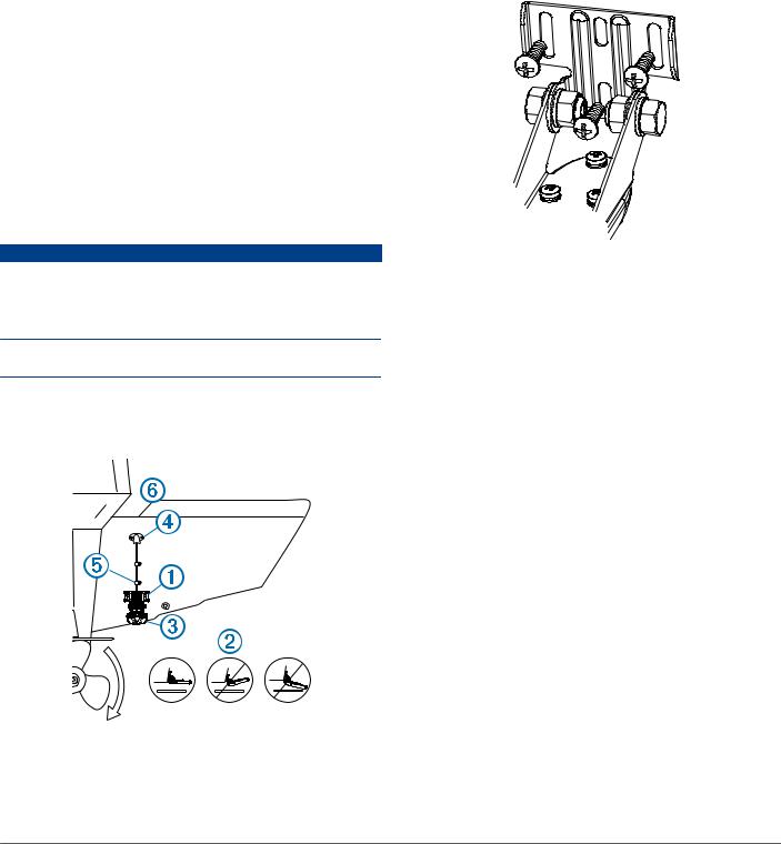
Installazione del trasduttore di poppa |
7 Per passare il cavo attraverso lo specchio di poppa, scegliere |
|
|
||
AVVERTENZA |
la posizione di un foro di riferimento sopra il livello dell'acqua |
|
Se si sta installando la staffa su fibra di vetro con delle viti, si |
à e contrassegnarla. |
|
consiglia di utilizzare una punta fresatrice per praticare una |
8 Posizionare un morsetto serracavo sul cavo del trasduttore Ä |
|
svasatura attraverso lo strato di resina. In questo modo è |
a circa un terzo della distanza tra il trasduttore e la parte |
|
possibile evitare crepe prodotte dal serraggio delle viti nello |
superiore dello specchio di poppa o del foro di riferimento. |
|
strato di resina. |
9 Contrassegnare la posizione dei fori di riferimento per il |
|
Non tagliare i cavi collegati al trasduttore. Diversamente la |
morsetto serracavo, quindi, con una punta da 3,2 mm |
|
garanzia non sarà più valida. |
(1/8 poll.), praticare un foro di riferimento di circa 10 mm |
|
1 Posizionare il supporto del trasduttore À in modo tale che la |
(3/8 poll.) di profondità. |
|
10Applicare del sigillante marino alla vite da 12 mm in |
||
parte centrale della parte inferiore del trasduttore sia in piano |
||
dotazione, quindi fissare il morsetto serracavo allo specchio |
||
rispetto al bordo inferiore dello specchio di poppa e parallela |
||
di poppa. |
||
al livello dell'acqua. |
||
11Ripetere i passi 10-12 per installare l'altro morsetto serracavo |
||
|
||
|
a circa due terzi della distanza tra il trasduttore e la parte |
|
|
superiore dello specchio di poppa o del foro di riferimento. |
|
|
12Se è stato contrassegnato un foro di riferimento nel passo 9, |
|
|
utilizzare una punta da trapano da 25 mm (1 poll.) per |
|
|
praticare un foro passante attraverso lo specchio di poppa. |
|
|
13Passare il cavo del trasduttore sull'eco: |
|
|
• Se il cavo viene fatto passare attraverso il foro passante, |
|
|
inserirlo dal foro praticato al passo 14, quindi installare il |
|
|
coperchio di ingresso cavo Ã. |
|
|
• Se il cavo non viene fatto passare attraverso il foro |
|
|
passante, passarlo verso l'alto, sulla parte superiore dello |
|
|
specchio di poppa Å. |
|
|
Evitare di posizionare il cavo accanto ad altri fili elettrici o |
|
|
possibili fonti di interferenza elettrica. |
|
|
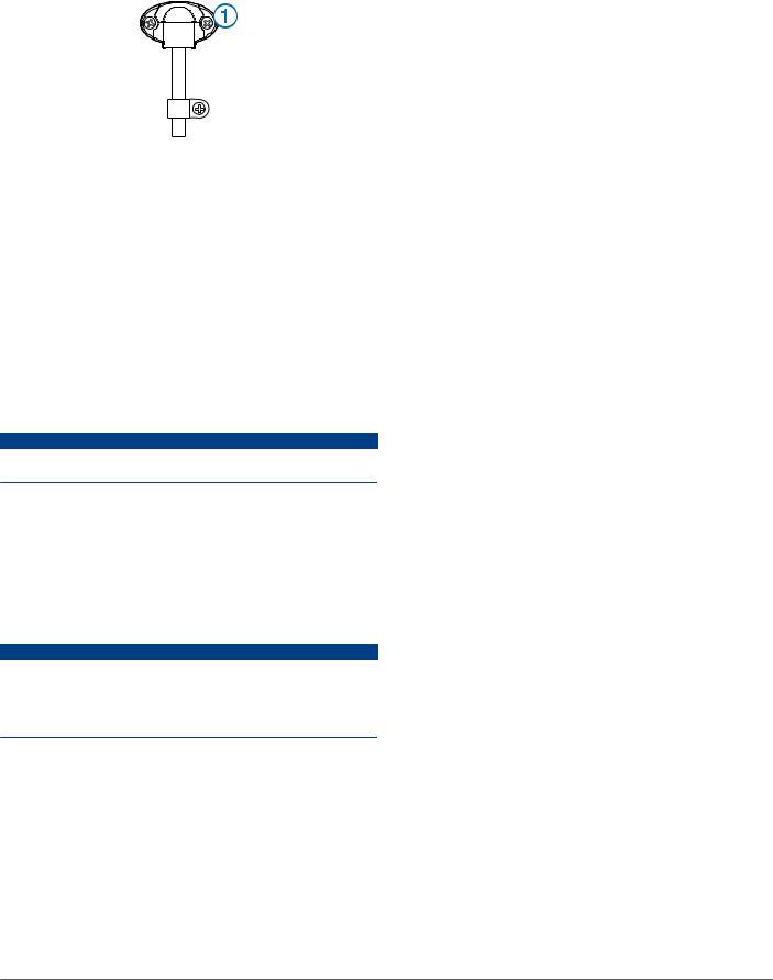
Installazione del passacavo |
|
|
Se il cavo è stato fatto passare attraverso lo specchio di poppa |
|
2 Allineare il trasduttore parallelamente al livello dell'acqua Á, |
dopo aver installato il trasduttore, è necessario installare il |
|
coperchio di ingresso cavo per evitare che l'acqua penetri |
||
quindi contrassegnare la posizione centrale dei due fori |
nell'imbarcazione. |
|
esterni e del foro centrale del supporto del trasduttore. |
1 Posizionare il passacavo À sul foro e sul cavo, con l'apertura |
|
3 Avvolgere del nastro su una punta di circa 4 mm (5/32 poll.) a |
||
rivolta verso il basso e contrassegnare la posizione dei due |
||
una distanza di 15 mm (19/32 poll.) dall'estremità della punta |
fori di riferimento. |
|
stessa per evitare di forare troppo in profondità. |
|
4Se si installa la staffa su fibra di vetro, inserire del nastro sulla posizione del foro di riferimento per ridurre l'incrinatura dello strato di resina.
5Con una punta da trapano di 4 mm (5/32 poll.) bit, praticare i fori di riferimento a una profondità di circa 15 mm (19/32 poll.) sulle posizioni contrassegnate.
9
2Rimuovere il passacavo e con una punta da 3,2 mm (1/8 poll.), praticare fori di riferimento di circa 10 mm (3/8 poll.) di profondità.
3Riempire il foro passante con del sigillante marino in modo da coprire completamente il cavo e verificare che il sigillante in eccesso si trovi intorno al foro e al cavo.
4Posizionare il passacavo sul foro e sul cavo, con l'apertura rivolta verso il basso.
5Applicare del sigillante marino alle viti M4 da 12 mm in dotazione, quindi fissare il passacavo allo specchio di poppa.
6 Rimuovere tutto il sigillante marino in eccesso.
Verifica dell'installazione
AVVERTENZA
Verificare che sull'imbarcazione non vi siano falle prima di lasciarla in acqua per un periodo di tempo prolungato.
Poiché il segnale dell'ecoscandaglio si propaga attraverso l'acqua, per un corretto funzionamento il trasduttore deve essere immerso in acqua. Fuori dall'acqua, infatti, non consente la lettura di profondità o distanza. Quando l'imbarcazione è in acqua, verificare la presenza di eventuali falle attorno ai fori delle viti inserite sotto il livello dell'acqua.
Verifica dell'installazione del trasduttore da poppa
AVVERTENZA
Regolare la profondità del trasduttore mediante piccoli incrementi. Posizionando il trasduttore a una profondità eccessiva si rischia di influire negativamente sulle prestazioni dell'imbarcazione, aumentando il rischio che il trasduttore possa colpire eventuali oggetti presenti in acqua.
Verificare l'installazione del trasduttore da poppa in mare aperto, senza ostacoli. Prestare attenzione all'ambiente circostante quando si verifica il trasduttore.
1 Accendere il chartplotter quando l'imbarcazione è in acqua.
2Governare l'imbarcazione a bassa velocità. Se il chartplotter funziona correttamente, aumentare gradualmente la velocità continuando a osservare lo schermo.
3Se all'improvviso si perde il segnale dell'ecoscandaglio o l'eco del fondale peggiora, prendere nota della velocità alla quale si verifica tale situazione.
4Riportare l'imbarcazione alla velocità in cui il segnale è stato perso, quindi virare moderatamente in entrambe le direzioni continuando a osservare il chartplotter.
5Se durante la virata la potenza del segnale aumenta,
regolare il trasduttore in modo tale che si estenda per altri 3 mm (1/8 poll.) sotto lo specchio di poppa dell'imbarcazione.
6Ripetere i passaggi da 2 a 4 finché la degradazione non viene eliminata.
7Se il segnale non migliora, spostare il trasduttore in un'altra posizione sullo specchio di poppa e ripetere il test.
10
Schwinger für die Heckspiegelmontage – Installationsanweisungen
Sie müssen sich beim Einbau des Garmin Schwingers an diese Anweisungen halten, um die bestmögliche Leistung zu erzielen und eine Beschädigung des Boots zu vermeiden.
Lesen Sie die gesamten Installationsanweisungen, bevor Sie mit der Installation beginnen. Sollten bei der Installation Probleme auftreten, wenden Sie sich an den Support von Garmin.
Registrieren des Geräts
Helfen Sie uns, unseren Service weiter zu verbessern, und füllen Sie die Online-Registrierung noch heute aus.
•Rufen Sie die Website http://my.garmin.com auf.
•Bewahren Sie die Originalquittung oder eine Fotokopie an einem sicheren Ort auf.
Kontaktaufnahme mit dem Support von Garmin
•Rufen Sie die Website www.garmin.com/support auf, um Informationen zum Support in den einzelnen Ländern zu erhalten.
•Nutzen Sie als Kunde in den USA die Rufnummern +1-913-397-8200 oder +1-800-800-1020.
•Nutzen Sie als Kunde in Großbritannien die Rufnummer 0808 238 0000.
•Nutzen Sie als Kunde in Europa die Rufnummer +44 (0) 870 850 1241.
Wichtige Sicherheitsinformationen
 WARNUNG
Lesen Sie alle Produktwarnungen und sonstigen wichtigen Informationen der Anleitung "Wichtige Sicherheitsund Produktinformationen", die dem Produkt beiliegt.
Sie sind für den sicheren und umsichtigen Betrieb des Boots verantwortlich. Mit einem Echolot erhalten Sie eine bessere Übersicht über die Situation im Wasser unter dem Boot. Es befreit Sie nicht von der Verantwortung, das Wasser um das Boot bei der Navigation zu beobachten.
 ACHTUNG
Wenn die Installation und Wartung des Geräts nicht entsprechend diesen Anweisungen vorgenommen wird, könnte es zu Schäden oder Verletzungen kommen.
Tragen Sie beim Bohren, Schneiden und Schleifen immer Schutzbrille, Gehörschutz und eine Staubschutzmaske.
HINWEIS
Prüfen Sie beim Bohren oder Schneiden stets die andere Seite der zu bearbeitenden Fläche.
Das Gerät muss von einem qualifizierten Installateur für Marinetechnik installiert werden.
Laden der neuen Software auf eine Speicherkarte
Sie müssen das Software-Update auf eine Speicherkarte kopieren.
1Legen Sie eine Speicherkarte in den Kartensteckplatz des Computers ein.
2Rufen Sie die Website www.garmin.com/support/software /marine.html auf.
3Wählen Sie neben „Garmin Marinenetzwerk mit SDSpeicherkarte“ die Option Herunterladen.
4 Lesen Sie die Bedingungen, und stimmen Sie ihnen zu.
5 Wählen Sie Herunterladen.
6Wählen Sie bei Bedarf die Option Laufen, oder speichern und öffnen Sie die Datei.
7Wählen Sie bei Bedarf das Laufwerk, das mit der Speicherkarte verbunden ist, und wählen Sie Weiter >
Fertigstellen.
Aktualisieren der Gerätesoftware
Bevor Sie die Software aktualisieren können, benötigen Sie eine Speicherkarte für Software-Updates oder müssen die aktuelle Software auf eine Speicherkarte laden.
1 Schalten Sie den Kartenplotter ein.
2Wenn das Hauptmenü angezeigt wird, legen Sie die Speicherkarte in den Kartensteckplatz ein.
HINWEIS: Damit die Anweisungen für das Software-Update angezeigt werden, muss das Gerät vollständig hochgefahren sein, bevor Sie die Karte einlegen.
3 Folgen Sie den Anweisungen auf dem Bildschirm.
4Warten Sie mehrere Minuten, während das Software-Update abgeschlossen wird.
Das Gerät kehrt nach Abschluss des Software-Updates zum normalen Betriebsmodus zurück.
5Entnehmen Sie die Speicherkarte.
HINWEIS: Falls die Speicherkarte vor dem vollständigen Neustart des Geräts entnommen wird, kann das SoftwareUpdate nicht abgeschlossen werden.
Erforderliches Werkzeug
•Bohrmaschine und Bohrer
•Zwei Inbusschlüssel, 13 mm
•Kreuzschraubendreher, Nr. 2
•Klebeband
•Seewassertaugliches Dichtungsmittel
Informationen zum Schwinger
Der Schwinger sendet und empfängt Schallwellen durch das Wasser und leitet Schallwelleninformationen an Ihr Garmin Echolot weiter.
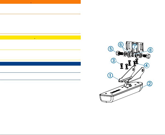
Zusammensetzen des Schwingers
1 Befestigen Sie die Halterung am Schwinger . Verwenden
À Á
Sie dazu die mitgelieferten 8-mm-M4-Schrauben und die
Â
4-mm-Klemmscheiben .
Ã
11
2 Befestigen Sie die Halterung am Halter . Verwenden Sie
Æ
dazu die mitgelieferten 16-mm-M8-Schrauben , die M8-
Ä
Unterlegscheiben und die M8-Sicherungsmuttern .
Å Ç
Installieren des Schwingers an einem Heckspiegel
Hinweise zur Auswahl des Montageorts
•Der Schwinger sollte so nahe wie möglich an der Bootsmitte montiert sein.
•Der Schwinger sollte nicht hinter Stabilisierungsflügeln, Verstrebungen, Armaturen, Wassereintritten oder Ausflussöffnungen oder hinter anderen Stellen montiert werden, an denen Blasen oder Wasserturbulenzen entstehen.
Damit der Schwinger optimal funktioniert, muss er sich in homogenem Wasser (ohne Turbulenzen) befinden.
•Der Schwinger sollte nicht an Stellen montiert werden, an denen er beim Zuwasserlassen, Schleppen oder Unterstellen beschädigt werden könnte.
•Bei Booten mit einer Schiffsschraube darf der Schwinger nicht im Pfad des Propellers montiert werden.
Der Schwinger kann zu einem Hohlsog führen, wodurch sich die Fahrleistung des Schiffes verschlechtern und die Schiffsschraube beschädigt werden kann.
•Bei Booten mit zwei Schiffsschrauben sollte der Schwinger möglichst zwischen den Antrieben montiert werden.
Installieren der Hardware für die Installation am Heckspiegel
HINWEIS
Wenn Sie die Halterung in Glasfasermaterial einlassen und festschrauben, wird die Verwendung eines Senkkopfbohrers empfohlen, um die Ansenkung nur durch die oberste GelcoatSchicht zu bohren. Dadurch wird Rissen in der obersten Gelschicht beim Anziehen der Schrauben vorgebeugt.
Die mit dem Schwinger verbundenen Kabel sollten nicht gekürzt werden, da dadurch die Garantie erlischt.
1 Positionieren Sie die Schwingerhalterung so, dass die
À
Mitte der Unterseite des Schwingers auf gleicher Höhe ist wie Unterseite des Heckspiegels und dass sie parallel zur Wasserlinie ausgerechnet ist.
2 Richten Sie den Schwinger parallel zur Wasserlinie aus,
Á
und kennzeichnen Sie die Mitte der zwei äußeren Löcher und das Loch in der Mitte der Schwingerhalterung.
3Wickeln Sie in einem Abstand von 4 mm (5/32 Zoll) von der Spitze eines 15-mm-Bohrers (19/32 Zoll) ein Stück Klebeband
um den Bohrer, damit die Vorbohrungen nicht zu tief gebohrt werden.
4Platzieren Sie bei der Installation der Halterung auf Glasfaser einen Streifen Klebeband über der Position der Vorbohrung, um Rissen in der obersten Gelschicht vorzubeugen.
5Bringen Sie mit einem 4-mm-Bohrer (5/32 Zoll) an den markierten Stellen die Vorbohrungen ca. 15 mm (19/32 Zoll) tief an.
6Tragen Sie seewassertaugliches Dichtungsmittel auf die mitgelieferten 20-mm-Schrauben auf, und befestigen Sie den Schwinger am Heckspiegel.
HINWEIS: Eine dritte Schraube, die am unteren, mittleren Schraubenloch angebracht wird, dient zur Stabilisierung der Halterung.
7Wenn Sie das Kabel durch den Heckspiegel führen müssen, wählen Sie die Position der Vorbohrung so, dass sie
ausreichend über der Wasserlinie liegt, und markieren Sie
Ã
die Stelle.
8Bringen Sie in einer Entfernung von etwa einem Drittel des Abstands zwischen dem Schwinger und der Oberkante des Heckspiegels oder der Vorbohrung eine Kabelklemme am
Schwingerkabel an.
Ä
9Markieren Sie die Position der Vorbohrung für die
Kabelklemme, und bringen Sie mit einem 3,2-mm-Bohrer (1/8 Zoll) eine ca. 10 mm (3/8 Zoll) tiefe Vorbohrung an.
10Tragen Sie seewassertaugliches Dichtungsmittel auf die mitgelieferte 12-mm-Schraube auf, und befestigen Sie die Kabelklemme am Heckspiegel.
11Wiederholen Sie die Schritte 10 bis 12, um die andere Kabelklemme in einer Entfernung von etwa zwei Dritteln des Abstands zwischen dem Schwinger und der Oberkante des Heckspiegels oder der Vorbohrung anzubringen.
12Wenn Sie in Schritt 9 eine Vorbohrung markiert haben, bringen Sie mit einem 25-mm-Bohrer (1 Zoll) ein Durchführungsloch an, das durch den gesamten Heckspiegel reicht.
13Führen Sie das Schwingerkabel zum Echolot:
•Wenn Sie das Kabel durch ein Durchführungsloch verlegen, führen Sie es durch das in Schritt 14 gebohrte Loch, und montieren Sie die Abdeckung für die
Kabelführung .
Ã
•Wenn Sie das Kabel nicht durch ein Durchführungsloch verlegen, führen Sie das Kabel nach oben und über die
Oberseite des Heckspiegels .
Å
Verlegen Sie das Kabel nicht zusammen mit Elektroleitungen oder anderen elektrischen Störquellen.
Montieren der Abdeckung für die Kabeleinführung
Wenn Sie das Kabel nach der Installation des Schwingers durch den Heckspiegel geführt haben, sollten Sie die Abdeckung für
12
die Kabeleinführung montieren, damit kein Wasser in das Boot eindringt.
1 Platzieren Sie die Abdeckung für die Kabeleinführung über
À
dem Loch und dem Kabel, sodass die Einführung nach unten zeigt. Kennzeichnen Sie die Position der zwei Vorbohrungen.
2Entfernen Sie die Abdeckung für die Kabeleinführung, und bringen Sie mit einem 3,2-mm-Bohrer (1/8 Zoll) die Vorbohrungen ca. 10 mm (3/8 Zoll) tief an.
3Füllen Sie das Durchführungsloch mit seewassertauglichem Dichtungsmittel, bis das Kabel gänzlich bedeckt ist und das Loch und das Kabel mit überschüssigem Dichtungsmittel bedeckt sind.
4Platzieren Sie die Abdeckung für die Kabeleinführung über dem Loch und dem Kabel, wobei die Einführung nach unten zeigt.
5Tragen Sie seewassertaugliches Dichtungsmittel auf die mitgelieferten M4-Schrauben (12 mm) auf, und befestigen Sie die Abdeckung für die Kabeleinführung am Heckspiegel.
6Wischen Sie überschüssiges seewassertaugliches Dichtungsmittel ab.
Testen der Installation
HINWEIS
Überprüfen Sie das Boot auf Undichtigkeiten, bevor Sie es für längere Zeit im Wasser lassen.
Da zur Übertragung des Echolotsignals Wasser erforderlich ist, muss sich der Schwinger im Wasser befinden, um ordnungsgemäß zu funktionieren. Wenn sich der Schwinger außerhalb des Wassers befindet, können keine Tiefenoder Entfernungsmessungen erstellt werden. Überprüfen Sie beim Zuwasserlassen des Boots die Schraubenlöcher unterhalb der Wasserlinie auf Undichtigkeiten.
Testen der Installation des Schwingers am Heckspiegel
HINWEIS
Verändern Sie die Tiefeneinstellung des Schwingers nur um kleine Werte. Eine zu tiefe Anordnung des Schwingers kann das Fahrverhalten des Boots nachteilig beeinflussen und birgt die Gefahr, dass der Schwinger unter der Wasseroberfläche befindliche Objekte berührt.
Testen Sie die Installation des Schwingers am Heckspiegel in offenem Wasser in einem Gebiet ohne Hindernisse. Achten Sie während des Testens des Schwingers auf Ihre Umgebung.
1Das Boot muss sich im Wasser befinden. Schalten Sie den Kartenplotter dann ein.
2Fahren Sie das Boot mit geringer Geschwindigkeit. Wenn der Kartenplotter ordnungsgemäß zu funktionieren scheint, erhöhen Sie die Geschwindigkeit allmählich, und beobachten Sie dabei den Kartenplotter.
3Geht das Echolotsignal plötzlich verloren oder ist das Bodensignal stark beeinträchtigt, notieren Sie die Geschwindigkeit, bei der dies auftritt.
4Reduzieren Sie die Geschwindigkeit bis zu dem Wert, bei dem das Signal verloren ging. Fahren Sie leichte Kurven in beide Richtungen, und beobachten Sie dabei den Kartenplotter.
5Wenn sich das Signal während der Kurvenfahrt verbessert,
stellen Sie den Schwinger so ein, dass er weitere 3 mm (1/8 Zoll) unter dem Heckspiegel des Boots herausragt.
6Wiederholen Sie die Schritte 2 bis 4, bis die Signalverschlechterung beseitigt ist.
7Verbessert sich das Signal nicht, bringen Sie den Schwinger an einer anderen Stelle am Heckspiegel an, und wiederholen Sie den Test.
13
Instrucciones de instalación del transductor de montaje en espejo de popa
Para obtener un rendimiento óptimo y evitar daños en la embarcación, debes instalar el transductor Garmin de acuerdo con estas instrucciones.
Lee todas las instrucciones de instalación antes de proceder a la misma. Si tienes dificultades con la instalación, ponte en contacto con el departamento de asistencia de Garmin.
Registro del dispositivo
Completa hoy mismo el registro en línea y ayúdanos a ofrecerte un mejor servicio.
•Visita http://my.garmin.com.
•Guarda la factura original o una fotocopia en un lugar seguro.
Contacto con el departamento de asistencia de Garmin
•Visita www.garmin.com/support para obtener información de asistencia relativa a tu país.
•En Estados Unidos, llama al 913-397-8200 o al 1-800-800-1020.
•En el Reino Unido, llama al 0808 238 0000.
•En Europa, llama al +44 (0) 870 850 1241.
Información importante sobre seguridad
 AVISO
AVISO
Consulta la guía Información importante sobre el producto y tu seguridad que se incluye en la caja del producto y en la que encontrarás advertencias e información importante sobre el producto.
Tú eres el responsable del uso seguro y prudente de la embarcación. La sonda es una herramienta que mejora tu conocimiento de las aguas que corren debajo de la embarcación. No te exime de la responsabilidad de observar las aguas alrededor de la embarcación mientras navegas.
 ADVERTENCIA
Si no se siguen estas instrucciones durante la instalación o mantenimiento de este equipo, se podrían llegar a producir daños personales o materiales.
Utiliza siempre gafas de seguridad, un protector de oídos y una máscara antipolvo cuando vayas a realizar orificios, cortes o lijados.
NOTIFICACIÓN
Al realizar orificios o cortes, comprueba siempre lo que hay al otro lado de la superficie.
La instalación de este equipo debe correr a cargo de un instalador profesional.
Carga del nuevo software en una tarjeta de memoria
Debes copiar la actualización de software en una tarjeta de memoria.
1 Introduce una tarjeta de memoria en la ranura del ordenador. 2 Accede a www.garmin.com/support/software/marine.html.
3Selecciona Descargar junto a "Red náutica Garmin con tarjeta SD".
4 Lee y acepta las condiciones.
5 Selecciona Descargar.
6Si es necesario, selecciona Ejecutar o guarda y abre el archivo.
7Si es necesario, selecciona la unidad asociada a la tarjeta de memoria y, a continuación, selecciona Siguiente > Finalizar.
Actualización del software del dispositivo
Para poder actualizar el software, debes obtener una tarjeta de memoria de actualización de software o cargar el software más reciente en una tarjeta de memoria.
1 Enciende el plotter.
2Cuando aparezca la pantalla de inicio, introduce la tarjeta de memoria en la ranura para tarjetas.
NOTA: para que aparezcan las instrucciones de actualización de software, el dispositivo debe haberse iniciado completamente antes de introducir la tarjeta.
3 Sigue las instrucciones que se muestran en la pantalla.
4Espera unos minutos a que se complete el proceso de actualización del software.
El dispositivo vuelve al funcionamiento normal cuando el proceso de actualización de software se completa.
5Extrae la tarjeta de memoria.
NOTA: si se extrae la tarjeta de memoria antes de que el dispositivo se reinicie por completo, la actualización de software no se completará.
Herramientas necesarias
•Taladro y brocas
•Dos llaves hexagonales de 3 mm
•Destornillador Phillips del número 2
•Cinta adhesiva protectora
•Sellador marino
Acerca del transductor
El transductor transmite y recibe ondas de sonido a través del agua, y transfiere la información de las ondas de sonido a tu sonda Garmin.
Ensamblaje del transductor
1 Fija el montaje al transductor con los tornillos M48 de
ÀÁ
mm y las arandelas de estrella de 4 mm que se
 à suministran.
2 Fija el soporte al montaje con los tornillos M8 de 16 mm
Æ
, las arandelas planas M8 y las tuercas de fijación M8
Ä Å que se suministran .
Ç
14
Loading...