


 Loading...
G1000TM
cockpit reference guide for the Mooney M20M & M20R
Copyright © 2004, 2005 Garmin Ltd. or its subsidiaries. All rights reserved.
This manual reflects the operation of System Software version 0424.10 or later for the Mooney M20M and M20R. Some differences in operation may be observed when comparing the information in this manual to earlier or later software versions.
Garmin International, Inc., 1200 East 151st Street, Olathe, Kansas 66062, U.S.A.
Tel: 913/397.8200 |
Fax: 913/397.8282 |
GarminAT, Inc., 2345Turner Road SE, Salem, OR 97302, U.S.A. |
|
Tel: 503/391.3411 |
Fax 503/364.2138 |
Garmin (Europe) Ltd., Unit 5,The Quadrangle,Abbey Park Industrial Estate, Romsey, Hampshire S051 9DL, U.K. |
|
Tel: 44/0870.8501241 |
Fax: 44/0870.8501251 |
Garmin Corporation, No. 68, Jangshu 2nd Road, Shijr,Taipei County,Taiwan |
|
Tel: 886/02.2642.9199 |
Fax: 886/02.2642.9099 |
Web SiteAddress: www.garmin.com
Except as expressly provided herein, no part of this manual may be reproduced, copied, transmitted, disseminated, downloaded or stored in any storage medium, for any purpose without the express written permission of Garmin. Garmin hereby grants permission to download a single copy of this manual and of any revision to this manual onto a hard drive or other electronic storage medium to be viewed for personal use, provided that such electronic or printed copy of this manual or revision must contain the complete text of this copyright notice and provided further that any unauthorized commercial distribution of this manual or any revision hereto is strictly prohibited.
Garmin® is a registered trademark of Garmin Ltd. or its subsidiaries, and G1000™ is a trademark of Garmin Ltd. or its subsidiaries. These trademarks may not be used without the express permission of Garmin.
NavData® is a registered trademark of Jeppesen, Inc.; Stormscope® and SkyWatch® are registered trademarks of L-3 Communications; and XM® is a registered trademark of XM Satellite Radio, Inc.
May 2005 |
190-00450-01 Rev.A |
Printed in the U.S.A. |
Garmin G1000 Cockpit Reference Guide for the Mooney M20M & M20R

WARNINGS,
CAUTIONS, & NOTES
WARNING: Navigation and terrain separation must NOT be predicated upon the use of the terrain function. The G1000 Terrain Proximity feature is NOT intended to be used as a primary reference for terrain avoidance and does not relieve the pilot from the responsibility of being aware of surroundings during flight. The Terrain Proximity feature is only to be used as an aid for terrain avoidance and is not certified for use in applications requiring a certified terrain awareness system. Terrain data is obtained from third party sources. Garmin is not able to independently verify the accuracy of the terrain data.
WARNING: The displayed minimum safe altitudes (MSAs) are only advisory in nature and should not be relied upon as the sole source of obstacle and terrain avoidance information. Always refer to current aeronautical charts for appropriate minimum clearance altitudes.
WARNING:The altitude calculated by G1000 GPS receivers is geometric height above Mean Sea Level and could vary significantly from the altitude displayed by pressure altimeters, such as the GDC 74A Air Data Computer, or other altimeters in aircraft. GPS altitude should never be used for vertical navigation. Always use pressure altitude displayed by the G1000 PFD or other pressure altimeters in aircraft.
WARNING: The Jeppesen database used in the G1000 system must be updated regularly in order to ensure that its information remains current. Updates are released every 28 days. A database information packet is included in the G1000 package. Pilots using an outdated database do so entirely at their own risk.
WARNING: The basemap (land and water data) must not be used for navigation, but rather only for non-navi- gational situational awareness. Any basemap indication should be compared with other navigation sources.
WARNING: Traffic information shown on the G1000 Multi Function Display is provided as an aid in visually acquiring traffic. Pilots must maneuver the aircraft based only uponATC guidance or positive visual acquisition of conflicting traffic.
WARNING: Use of the Stormscope interface for hazardous weather penetration is prohibited. Weather information on the G1000 MFD is approved only for weather avoidance, not penetration.
WARNING: Use of the GDL 69 Weather Interface for hazardous weather penetration is prohibited. Weather information provided by the GDL 69 is approved only for weather avoidance, not penetration.
Garmin G1000 Cockpit Reference Guide for the Mooney M20M & M20R |
i |
WARNINGS,
CAUTIONS, & NOTES
WARNING: NEXRAD weather data is to be used for long-range planning purposes only. Due to inherent delays in data transmission and the relative age of the data,NEXRAD weather data should not be used for short-range weather avoidance.
WARNING: The Garmin G1000, as installed in the Mooney M20M and M20R aircraft, has a very high degree of functional integrity. However, the pilot must recognize that providing monitoring and/or self-test capability for all conceivable system failures is not practical. Although unlikely, it may be possible for erroneous operation to occur without a fault indication shown by the G1000. It is thus the responsibility of the pilot to detect such an occurrence by means of cross-checking with all redundant or correlated information available in the cockpit.
WARNING: For safety reasons, G1000 operational procedures must be learned on the ground.
WARNING: The United States government operates the Global Positioning System and is solely responsible for its accuracy and maintenance. The GPS system is subject to changes which could affect the accuracy and performance of all GPS equipment. Portions of the Garmin G1000 utilize GPS as a precision electronic NAVigation AID (NAVAID). Therefore, as with all NAVAIDs, information presented by the G1000 can be misused or misinterpreted and, therefore, become unsafe.
WARNING: To reduce the risk of unsafe operation, carefully review and understand all aspects of the G1000 Pilot’s Guide documentation and the G1000 Flight Manual Supplement. Thoroughly practice basic operation prior to actual use. During flight operations, carefully compare indications from the G1000 to all available navigation sources, including the information from other NAVAIDs, visual sightings, charts, etc. For safety purposes, always resolve any discrepancies before continuing navigation.
WARNING: The illustrations in this guide are only examples. Never use the G1000 to attempt to penetrate a thunderstorm. Both the FAA Advisory Circular, Subject:Thunderstorms, and the Airman’s Information Manual (AIM) recommend avoiding “by at least 20 miles any thunderstorm identified as severe or giving an intense radar echo.”
CAUTION: The GDU 1040 PFD and MFD displays use a lens coated with a special anti-reflective coating that is very sensitive to skin oils, waxes, and abrasive cleaners. CLEANERS CONTAINING AMMONIA WILL HARM THE ANTI-REFLECTIVE COATING. It is very important to clean the lens using a clean, lint-free cloth and an eyeglass lens cleaner that is specified as safe for anti-reflective coatings.
ii |
Garmin G1000 Cockpit Reference Guide for the Mooney M20M & M20R |

WARNINGS,
CAUTIONS, & NOTES
CAUTION: The Garmin G1000 does not contain any user-serviceable parts. Repairs should only be made by an authorized Garmin service center. Unauthorized repairs or modifications could void both the warranty and the pilot’s authority to operate this device under FAA/FCC regulations.
NOTE:When using Stormscope,there are several atmospheric phenomena in addition to nearby thunderstorms that can cause isolated discharge points in the strike display mode. However, clusters of two or more discharge points in the strike display mode do indicate thunderstorm activity if these points reappear after the screen has been cleared.
NOTE: All visual depictions contained within this document, including screen images of the G1000 panel and displays, are subject to change and may not reflect the most current G1000 system. Depictions of equipment may differ slightly from the actual equipment.
NOTE:This device complies with part 15 of the FCC Rules. Operation is subject to the following two conditions:
(1) this device may not cause harmful interference, and (2) this device must accept any interference received, including interference that may cause undesired operation.
Garmin G1000 Cockpit Reference Guide for the Mooney M20M & M20R |
iii |

WARNINGS,
CAUTIONS, & NOTES
This page intentionally left blank.
iv |
Garmin G1000 Cockpit Reference Guide for the Mooney M20M & M20R |

RECORD OF REVISIONS
Part Number |
Change Summary |
190-00450-01 |
Reformat of manual. |
|
AddedWX 500 Stormscope |
|
Added XMWeather |
|
AddedADF/DME |
|
Added extended range fuel tanks |
|
Changes in EIS softkey labels |
|
|
Revision |
Date of Revision |
Affected Pages |
Description |
A |
5/25/05 |
i-Index-2 |
Initial release |
|
|
|
|
Garmin G1000 Cockpit Reference Guide for the Mooney M20M & M20R |
v |

RECORD OF REVISIONS
This page intentionally left blank.
vi |
Garmin G1000 Cockpit Reference Guide for the Mooney M20M & M20R |

TABLE OF CONTENTS
SECTION 1: SYSTEM OVERVIEW.................................... |
1-1 |
|
1.1 |
PFD/MFD Controls................................................... |
1-2 |
1.2 |
PFD Softkeys............................................................ |
1-4 |
1.3 |
MFD Softkeys.......................................................... |
1-6 |
1.4 |
MFD Page Groups................................................... |
1-8 |
1.5 |
Backlighting............................................................. |
1-8 |
SECTION 2: FLIGHT INSTRUMENTS.............................. |
2-1 |
|
2.1 |
Airspeed Indicator.................................................. |
2-3 |
|
Speed Indication ......................................................... |
2-3 |
|
Speed Ranges............................................................. |
2-3 |
|
AirspeedTrendVector ................................................. |
2-3 |
|
Vspeed References...................................................... |
2-3 |
2.2 |
Attitude Indicator.................................................. |
2-3 |
2.3 |
Altimeter.................................................................. |
2-4 |
|
Altitude Reference Bug................................................ |
2-4 |
|
AltitudeTrendVector................................................... |
2-4 |
|
Barometric Setting Box................................................ |
2-4 |
2.4 |
Vertical Deviation/Glideslope Indicator............ |
2-4 |
2.5 |
Marker Beacon Annunciations ............................ |
2-4 |
2.6 |
Vertical Speed Indicator....................................... |
2-5 |
2.7 |
Horizontal Situation Indicator (HSI)................... |
2-5 |
|
Course Pointer ............................................................ |
2-6 |
|
Course Deviation Indicator (CDI).................................. |
2-6 |
|
Bearing Pointers and InformationWindows.................. |
2-6 |
|
DME Radio (optional).................................................. |
2-7 |
|
Navigation Source....................................................... |
2-7 |
SECTION 3: ENGINE INDICATION SYSTEM (EIS).... |
3-1 |
|
3.1 |
Engine Display......................................................... |
3-1 |
3.2 |
Lean Engine Display............................................... |
3-1 |
|
Cylinder Select............................................................ |
3-1 |
3.3 |
Engine System Display.......................................... |
3-2 |
3.4 |
Flap & Trim Indications.......................................... |
3-2 |
|
RudderTrim Indicator.................................................. |
3-2 |
|
ElevatorTrim Indicator................................................. |
3-2 |
|
Flaps Position Indicator ............................................... |
3-2 |
SECTION 4: NAV/COM AND TRANSPONDER.......... |
4-1 |
|
4.1 |
Radio Status Indications....................................... |
4-3 |
4.2 |
Volume...................................................................... |
4-3 |
4.3 |
Automatic Squelch................................................. |
4-3 |
4.4 |
Quickly Activating 121.500 MHz.......................... |
4-3 |
4.5 |
Optional NAV Radios ............................................. |
4-3 |
|
ADF Radio (optional)................................................... |
4-3 |
|
DME Radio (optional).................................................. |
4-4 |
4.6 |
Frequency Auto-tuning ......................................... |
4-4 |
|
Auto-tuning on the PFD .............................................. |
4-4 |
|
Auto-tuning on the MFD ............................................. |
4-4 |
4.7 |
Transponder............................................................. |
4-5 |
|
Mode Selection........................................................... |
4-5 |
|
Ground Mode (Automatic)...................................... |
4-5 |
|
Reply Status........................................................... |
4-5 |
|
Code Selection....................................................... |
4-5 |
|
Flight ID Reporting...................................................... |
4-5 |
SECTION 5:AUDIO PANEL................................................ |
5-1 |
|
5.1 |
COM Radio Selection............................................. |
5-2 |
5.2 |
Marker Beacon Receiver....................................... |
5-2 |
|
Marker Beacon Signal Sensitivity ................................. |
5-2 |
5.3 |
Nav Radio Audio Selection................................... |
5-2 |
5.4 |
Intercom System (ICS) Isolation.......................... |
5-3 |
5.5 |
Intercom Squelch Control..................................... |
5-3 |
5.6 |
Digital Clearance Recorder with Playback |
|
|
Capability................................................................. |
5-4 |
SECTION 6:AUTOMATIC FLIGHT CONTROL............. |
6-1 |
|
SECTION 7: NAVIGATION.................................................. |
7-1 |
|
7.1 |
Navigation Map Page............................................ |
7-1 |
|
Select the MAP Page Group......................................... |
7-1 |
7.2 |
Direct-to Navigation.............................................. |
7-1 |
|
Direct-to Navigation from the MFD.............................. |
7-1 |
|
Direct-to Navigation from the PFD............................... |
7-2 |
7.3 |
Airport Information............................................... |
7-3 |
|
Select theAirport Information Page ............................. |
7-3 |
|
Enter aWaypoint Facility Name or City Location........... |
7-3 |
|
Access Runway Information......................................... |
7-3 |
|
Access Frequency Information...................................... |
7-3 |
7.4 |
Intersection Information...................................... |
7-4 |
|
Select the Intersection Information Page...................... |
7-4 |
|
Access Information on an Intersection ......................... |
7-4 |
7.5 |
NDB Information..................................................... |
7-4 |
|
Select the NDB Information Page................................. |
7-4 |
|
View Information on a Specific NDB ............................ |
7-4 |
7.6 |
VOR Information..................................................... |
7-5 |
|
Select theVOR Information Page ................................. |
7-5 |
|
Access Information on aVOR....................................... |
7-5 |
Garmin G1000 Cockpit Reference Guide for the Mooney M20M & M20R |
vii |

TABLE OF CONTENTS
7.7 |
User Waypoint Information Page ....................... |
7-5 |
7.8 |
Nearest Airports..................................................... |
7-5 |
|
NearestAirport Information on the MFD...................... |
7-5 |
|
NearestAirports Information on the PFD...................... |
7-6 |
7.9 |
Nearest Intersections............................................ |
7-6 |
|
Select the Nearest Intersections Page........................... |
7-6 |
|
View Information on the Nearest Intersection .............. |
7-7 |
7.10 Nearest NDB ............................................................ |
7-7 |
|
|
Select the Nearest NDB Page....................................... |
7-7 |
|
Access Information on a Specific NDB.......................... |
7-7 |
7.11 Nearest VOR............................................................. |
7-7 |
|
|
Select the NearestVOR Page ....................................... |
7-7 |
|
View Information on the NearestVOR.......................... |
7-7 |
|
Select and Load aVOR Frequency................................ |
7-8 |
7.12 Nearest User Waypoint.......................................... |
7-8 |
|
|
Select the Nearest UserWaypoint Page........................ |
7-8 |
|
Select a Nearest UserWaypoint................................... |
7-8 |
7.13 Nearest Frequencies.............................................. |
7-8 |
|
|
Select the Nearest Frequencies Page............................ |
7-8 |
|
Select and Load the NearestARTCC, FSS, orWeather |
|
|
Frequency ................................................................... |
7-9 |
7.14 Nearest Airspaces................................................... |
7-9 |
|
|
Select the NearestAirspaces Page................................ |
7-9 |
|
AirspaceAlerts Box ..................................................... |
7-9 |
|
ViewAdditional Details for a ListedAirspace................ |
7-9 |
|
View and Quickly Load the Frequency for a |
|
|
ControllingAgency...................................................... |
7-9 |
SECTION 8: FLIGHT PLANNING...................................... |
8-1 |
|
8.1 |
User Defined Waypoints........................................ |
8-1 |
|
Select the UserWPT Information Page......................... |
8-1 |
|
Create a New UserWaypoint....................................... |
8-1 |
|
Create UserWaypoints from the Navigation |
|
|
Map Page................................................................... |
8-1 |
|
Modify a UserWaypoint .............................................. |
8-2 |
|
Delete a UserWaypoint............................................... |
8-2 |
8.2 |
Viewing the Active Flight Plan............................ |
8-2 |
8.3 |
Activate a Stored Flight Plan............................... |
8-2 |
8.4 |
Activate a Flight Plan Leg .................................... |
8-2 |
8.5 |
Stop Navigating a Flight Plan.............................. |
8-3 |
8.6 |
Invert Active Flight Plan....................................... |
8-3 |
8.7 |
Create a New Flight Plan...................................... |
8-3 |
|
Create a new flight plan using the PFD........................ |
8-4 |
8.8 |
Load a Departure ................................................... |
8-4 |
8.9 |
Load an Arrival........................................................ |
8-4 |
8.10 |
Load an Approach .................................................. |
8-4 |
8.11 |
Remove a Departure,Arrival, or Approach |
|
|
from a Flight Plan................................................... |
8-5 |
8.12 |
Store A Flight Plan ................................................. |
8-5 |
8.13 |
Edit a Stored Flight Plan....................................... |
8-5 |
8.14 |
Delete a Waypoint from the Flight Plan............ |
8-5 |
8.15 |
Invert and activate a Stored Flight Plan........... |
8-5 |
8.16 |
Copy a Flight Plan .................................................. |
8-6 |
8.17 |
Delete a Flight Plan ............................................... |
8-6 |
8.18 |
Graphical Flight Plan Creation ............................ |
8-6 |
8.19 |
Trip Planning............................................................ |
8-6 |
SECTION 9: PROCEDURES................................................ |
9-1 |
|
9.1 |
Arrivals and Departures........................................ |
9-1 |
|
Load andActivate a Departure Procedure .................... |
9-1 |
|
Load andActivateAnArrival Procedure........................ |
9-1 |
9.2 |
Approaches.............................................................. |
9-2 |
|
Load and/orActivate anApproach Procedure............... |
9-2 |
|
ActivateAnApproach in theActive Flight Plan............. |
9-3 |
SECTION 10: HAZARD AVOIDANCE........................... |
10-1 |
|
10.1 Customizing the Hazard Displays on the |
|
|
|
Navigation Map.................................................... |
10-1 |
10.2 STORMSCOPE® (Optional).................................. |
10-1 |
|
|
Displaying Stormscope Lightning Data on the |
|
|
Navigation Map Page................................................ |
10-1 |
|
Stormscope Page....................................................... |
10-2 |
10.3 XM Weather (Optional)....................................... |
10-3 |
|
|
Displaying METAR andTAF information on the |
|
|
Airport Information Page........................................... |
10-3 |
|
DisplayingWeather on theWeather Data Link Page ... |
10-4 |
|
NEXRAD Limitations............................................. |
10-4 |
|
Map Panning Information –Weather Data Link Page .10-5 |
|
|
Weather Product Symbols.......................................... |
10-5 |
|
Weather ProductAge................................................ |
10-6 |
10.4 Traffic Information Service (TIS)....................... |
10-7 |
|
|
DisplayingTraffic on theTraffic Map Page................... |
10-7 |
|
DisplayingTraffic on the Navigation Map................... |
10-7 |
|
TISAudioAlert.......................................................... |
10-7 |
viii |
Garmin G1000 Cockpit Reference Guide for the Mooney M20M & M20R |
TABLE OF CONTENTS
10.5 |
Skywatch Traffic Advisory System |
|
|
(TAS)(Optional)...................................................... |
10-8 |
|
DisplayingTraffic on theTraffic Map Page................... |
10-8 |
|
DisplayingTraffic on the Navigation Map................... |
10-8 |
10.6 |
Terrain And Obstacle Proximity ........................ |
10-9 |
|
DisplayingTerrain and Obstacles on theTerrain |
|
|
Proximity Page.......................................................... |
10-9 |
|
DisplayingTerrain and Obstacles on the |
|
|
Navigation Map........................................................ |
10-9 |
SECTION 11:ABNORMAL OPERATION..................... |
11-1 |
|
11.1 |
Reversionary Mode.............................................. |
11-1 |
11.2 |
Abnormal COM Operation.................................. |
11-2 |
11.3 |
Unusual Attitudes................................................. |
11-2 |
SECTION 12:ANNUNCIATIONS & ALERTS.............. |
12-1 |
|
12.1 |
Alert Level Definitions........................................ |
12-2 |
12.2 |
M20M/M20R Aircraft Alerts................................ |
12-2 |
|
VoiceAlerts............................................................... |
12-2 |
|
MessageAdvisoryAlerts............................................ |
12-2 |
12.3 |
G1000 System Annunciations ............................ |
12-3 |
|
VoiceAlerts............................................................... |
12-5 |
|
AudioAlerts.............................................................. |
12-5 |
12.4 |
G1000 System Message Advisories.................. |
12-6 |
|
MFD & PFD MessageAdvisories................................. |
12-7 |
|
Database MessageAdvisories.................................... |
12-8 |
|
GMA 1347 MessageAdvisories................................. |
12-9 |
|
GIA 63 MessageAdvisories....................................... |
12-9 |
|
GEA 71 MessageAdvisories .................................... |
12-11 |
|
GTX 33 MessageAdvisories..................................... |
12-12 |
|
GRS 77 MessageAdvisories..................................... |
12-12 |
|
GMU 44 MessageAdvisories................................... |
12-13 |
|
GDL 69 MessageAdvisories..................................... |
12-13 |
|
GDC 74A MessageAdvisories.................................. |
12-13 |
|
Miscellaneous MessageAdvisories........................... |
12-14 |
INDEX................................................................................... |
|
Index-1 |
Garmin G1000 Cockpit Reference Guide for the Mooney M20M & M20R |
ix |

TABLE OF CONTENTS
This page intentionally left blank.
x |
Garmin G1000 Cockpit Reference Guide for the Mooney M20M & M20R |

SECTION 1: SYSTEM OVERVIEW
The purpose of this Cockpit Reference Guide is to provide the pilot a resource with which to find operating instructions on the major features of the G1000 system more easily. It is not intended to be a comprehensive operating guide. Complete operating procedures for the complete system are found in the following documents:
•G1000 Primary Flight Display Pilot’s Guide
•G1000 VHF NAV/COM Pilot’s Guide
•G1000 Transponder Pilot’s Guide
•G1000 GMA 1347 Audio Panel Pilot’s Guide and Supplement
•G1000 Engine Indication System Pilot’s Guide
•G1000 Multi Function Display Pilot’s Guide
•G1000 Optional Equipment Addendum
SECTION 1
SYSTEM OVERVIEW
This guide gives the pilot abbreviated operating instructions for the Primary Flight Display (PFD), Multi Function Display (MFD), and the GMA 1347 Audio Panel System.
NOTE: The pilot should read and thoroughly understand the Mooney M20M/M20R Aircraft Flight Manual Supplement (AFMS) for limitations, procedures and operational information not contained in this Cockpit Reference Guide. The Mooney M20M/M20RAircraft Flight Manual Supplement always takes precedence over the information found in this guide.
Garmin G1000 Cockpit Reference Guide for the Mooney M20M & M20R |
1-1 |
SECTION 1
SYSTEM OVERVIEW
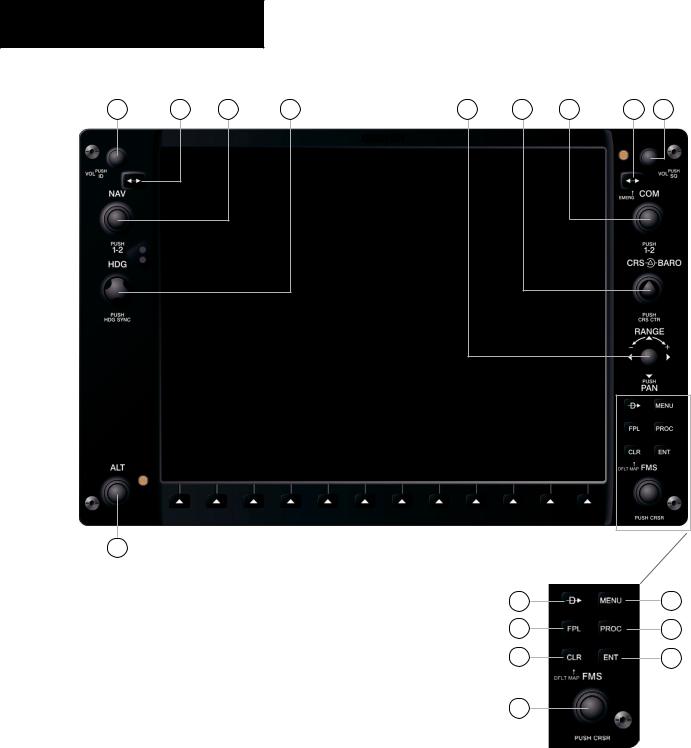
1.1PFD/MFD CONTROLS
1 |
2 |
3 |
4 |
5 |
6 |
7 |
8 |
9 |
17 |
Figure 1-1 PFD/MFD Controls |
10 |
14 |
11 |
15 |
12 |
16 |
13 |
|
1-2 |
Garmin G1000 Cockpit Reference Guide for the Mooney M20M & M20R |

(1)NAV VOL/ID Knob – Controls the NAV audio level. Press to toggle the Morse code identifier ON and OFF. Volume level is shown in the field as a percentage.
(2)NAV Frequency Toggle Key – Toggles the standby and active NAV frequencies.
(3)Dual NAV Knob – Tunes the MHz (large knob) and kHz (small knob) standby frequencies for the NAV receiver. Press to toggle the tuning cursor (light blue box) between the NAV1 and NAV2 fields.
(4)Heading Knob – Turn to manually select a heading on the HSI. When pressed, it synchronizes the heading bug with the compass lubber line.
(5)Joystick – Changes the map range when rotated. Activates the map pointer when pressed.
(6)CRS/BARO Knob – The large knob sets the altimeter barometric pressure and the small knob adjusts the course. The course is only adjustable when the HSI is in VOR1, VOR2, or OBS/SUSP mode. Pressing this knob centers the CDI on the currently selected VOR.
(7)Dual COM Knob – Tunes the MHz (large knob) and kHz (small knob) standby frequencies for the COM transceiver. Pressing this knob toggles the tuning cursor (light blue box) between the COM1 and COM2 fields.
(8)COM Frequency Toggle Key – Toggles the standby and active COM frequencies. Pressing and holding this key for two seconds automatically tunes the emergency frequency (121.5 MHz) in the active frequency field.
(9)COM VOL/SQ Knob – Controls COM audio level. Pressing this knob turns the COM automatic squelch ON and OFF. Audio volume level is shown in the field as a percentage.
(10)Direct-to Key – Allows the user to enter a destination waypoint and establish a direct course to the selected destination (specified by the identifier, chosen from the active route, or taken from the map cursor position).
(11)FPL Key – Displays the active Flight Plan Page for creating and editing the active flight plan, or for accessing stored flight plans.
SECTION 1
SYSTEM OVERVIEW
(12)CLR Key (DFLT MAP) – Erases information, cancels an entry, or removes page menus. To display the Navigation Map Page immediately, press and hold CLR (MFD only).
(13)Dual FMS Knob – Used to select the page to be viewed (only on the MFD). The large knob selects a page group (MAP, WPT, AUX, NRST), while the small knob selects a specific page within the page group. Pressing the small knob turns the selection cursor ON and OFF.
(14)MENU Key – Displays a context-sensitive list of options. Thislistallowstheusertoaccessadditionalfeatures, or to make setting changes that relate to certain pages.
(15)PROC Key – Selects approaches, departures and arrivals from the flight plan. If a flight plan is used, available procedures for the departure and/or arrival airport are automatically suggested. If a flight plan is not used, the desired airport and the desired procedure may be selected. This key selects IFR departure procedures (DPs), arrival procedures (STARs) and approaches (IAPs) from the database and loads them into the active flight plan.
(16)ENT Key – Accepts a menu selection or data entry. This key is used to approve an operation or complete data entry. It is also used to confirm selections and information entries.
(17)Dual ALT Knob – Sets the reference altitude in the box located above the Altimeter. The large knob selects the thousands, while the small knob selects the hundreds.
Garmin G1000 Cockpit Reference Guide for the Mooney M20M & M20R |
1-3 |
SECTION 1
SYSTEM OVERVIEW
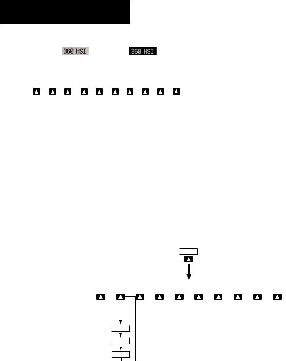
1.2PFD SOFTKEYS
|
|
|
|
Softkey ON |
Softkey OFF |
|
||||||||
|
|
|
|
|
|
|
|
(optional) |
|
|
|
|
|
|
INSET |
|
PFD |
|
OBS |
|
CDI |
|
ADF/DME |
XPDR |
IDENT |
TMR/REF |
|
NRST |
ALERTS |
Figure 1-2 PFD Top Level Softkeys
INSET – Press to display the Inset Map in the lower left corner of the PFD.
OFF – Press to remove the Inset Map DCLTR (3) – Press momentarily to select the
desired amount of map detail. The declutter level appears adjacent to the DCLTR softkey.
•Nodeclutter:Allmapfeaturesarevisible
•Declutter–1:Declutterslanddata
•Declutter–2:DeclutterslandandSUAdata
•Declutter–3:DeclutterslargeNAVdataremaining
(removeseverythingexcepttheactiveflightplan) TRAFFIC – Press to display TIS traffic on the map. TOPO – Press to display topographical data (i.e., coastlines, terrain, rivers, lakes, etc.) and
elevation scale on the inset map.
INSET
TERRAIN – Press to display terrain information on the inset map.
STRMSCP (optional) – Press to display the Stormscope lightning data on the inset map (within a 200 nm radius of the aircraft).
NEXRAD (optional) – Press to display NEXRAD precititation data on the inset map.
XM LTNG (optional) – Press to display the XM Radio lightning data on the inset map.
BACK – Press to return to the previous level softkey configuration.
PFD – Press to display the additional softkeys for additional configurations to the PFD. METRIC – Press to display the current and refer-
ence altitudes in meters, in addition to feet. Pressing the metric softkey also changes the barometric setting to hectopascals.
DFLTS – Press to reset default settings on the PFD. DME(optional)–PresstodisplaytheDMEinforma-
tion window.
BRG1(bearing)–Presstocyclethroughthefollow- ingNavsources,makingthepointertheindicatorforthecorrespondingsourceanddisplaying the the appropriate information.
|
|
|
|
|
|
|
|
|
|
(optional) |
(optional) |
|
(optional) |
|
|
|
|
|
|
|
DCLTR |
|
TRAFFIC |
|
|
|
TERRAIN |
|
STRMSCP |
|
NEXRAD |
|
|
|
BACK |
|
ALERTS |
OFF |
|
|
|
TOPO |
|
|
|
|
XM LTNG |
|
|
|||||||
DCLTR-1
DCLTR-2
DCLTR-3
Press the BACK or OFF softkey to return to the top level softkeys
Figure 1-3 PFD Softkey Flow Chart – 1
1-4 |
Garmin G1000 Cockpit Reference Guide for the Mooney M20M & M20R |

SECTION 1
SYSTEM OVERVIEW
PFD
(optional)
|
|
|
|
DME |
|
BRG1 |
|
360 HSI |
|
ARC HSI |
|
BRG2 |
|
|
|
BACK |
|
ALERTS |
METRIC |
|
DFLTS |
|
|
|
|
|
|
STD BARO |
|
|
Press the DFLTS softkey to change the PFD metric values to standard
Press the STD BARO or BACK softkeys to return to the top level softkeys
Figure 1-4 PFD Softkey Flow Chart – 2
NAV1 – Displays NAV1 waypoint frequency or identifier and DME information in the BRG1 information window.
GPS–DisplaysGPSwaypointidentifierandGPS distance information in the BRG1 information window.
ADF – Displays ADF waypoint frequency in the BRG1 information window.
OFF – Removes the BRG1 information window.
360 HSI – Press to display the 360° compass rose. ARC HSI – Press to display the 140° viewable arc. BRG2(bearing)–Presstocyclethroughthefollow- ingNavsources,makingthepointertheindicatorforthecorrespondingsourceanddisplaying
the the appropriate information.
NAV2 –Displays NAV2 waypoint frequency or identifier and DME information in the BRG2 information window.
GPS–DisplaysGPSwaypointidentifierandGPS distance information in the BRG2 information window.
ADF – Displays ADF waypoint frequency in the BRG2 information window.
OFF – Removes the BRG2 information window.
STD BARO – Press to set the barometric pressure to 29.92 inches of mercury (1013 hPa by pressing the METRIC softkey).
BACK–Press to return to the previous level softkeys.
OBS – Press to select OBS mode on the CDI when navigating by GPS (only available with active leg).
CDI – Press to change navigation mode on the CDI between GPS, VOR1 and VOR2.
ADF/DME(optional) – Press to display the ADF/DME Tuning window.
XPDR – Press to display the transponder mode selection softkeys.
STBY – Press to select standby mode. ON – Press to select mode A.
ALT – Press to select altitude reporting mode. VFR – Press to automatically squawk 1200 (only
in the U.S.A., refer to ICAO standards for VFR codes in other countries).
CODE – Press to display transponder code selection softkeys 0-7.
0 through 7 – Press numbers to enter code. IDENT – Press to provide special aircraft position identification to Air Traffic Control (ATC).
BKSP – Press to remove numbers entered one at a time.
Garmin G1000 Cockpit Reference Guide for the Mooney M20M & M20R |
1-5 |
SECTION 1
SYSTEM OVERVIEW
|
|
(optional) |
|
|
|
|
|
OBS |
CDI |
ADF/DME |
XPDR |
IDENT |
TMR/REF |
NRST |
ALERTS |
CDI (VOR1)
CDI (VOR2)

 Press the BACK softkey GPS to return to the top level
softkeys
|
|
ON |
|
ALT |
|
VFR |
|
CODE |
|
IDENT |
|
|
|
ALERTS |
STBY |
|
|
|
|
|
|
BACK |
|
Press the BACK softkey
to return to the top level softkeys
|
|
|
|
|
|
|
|
|
|
|
|
|
|
|
|
IDENT |
|
BKSP |
|
BACK |
|
ALERTS |
0 |
|
1 |
|
2 |
|
3 |
|
4 |
|
5 |
|
6 |
|
7 |
|
|
|
|
Figure 1-5 PFD Softkey Flow Chart – 3
BACK – Press to return to the previous level softkeys.
IDENT – Press to provide special aircraft position identification to Air Traffic Control (ATC).
BACK – Press to return to the previous level softkeys.
IDENT – Press to provide special aircraft position identification to Air Traffic Control (ATC).
TMR/REF – Press to display the Timer/References window.
NRST – Press to display the Nearest Airports window.
ALERTS – Press to display the Alerts window.
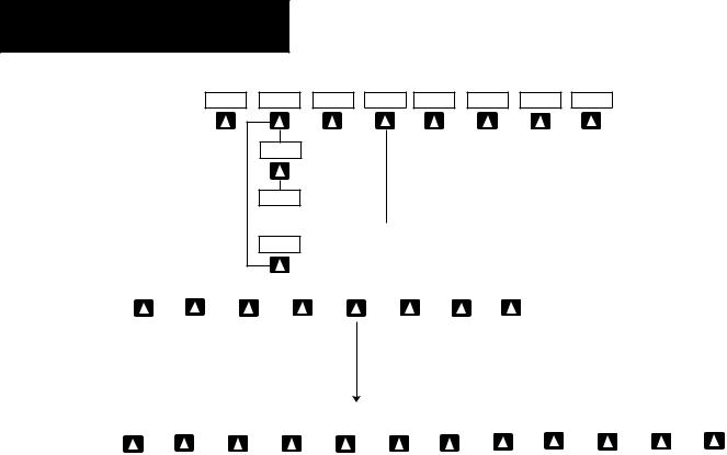
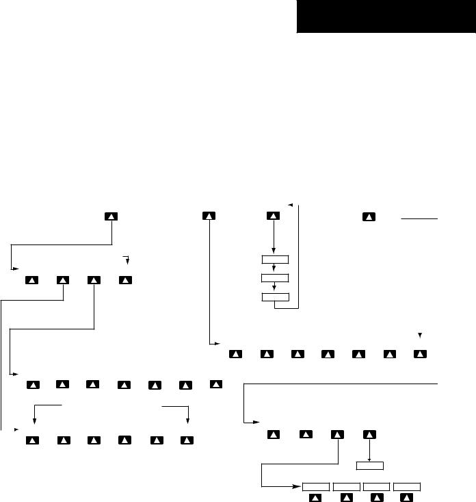
1.3MFD SOFTKEYS
ENGINE – Pressing this softkey makes available the LEAN and SYSTEM softkeys which in turn access the Lean Page and the System Page, respectively.
MAP – pressing this softkey enables the following softkeys:
TRAFFIC – pressing this softkey displays/ removes Traffic on the Navigation Map.
TOPO – pressing this softkey displays or removes topographic information on the Navigation Map.
TERRAIN – pressing this softkey displays/ removes terrain and obstacle data on the Navigation Map.
1-6 |
Garmin G1000 Cockpit Reference Guide for the Mooney M20M & M20R |
SECTION 1
SYSTEM OVERVIEW
STRMSCP (optional) – pressing this softkey displays/removes Stormscope lightning data on the Navigation Map.
NEXRAD (optional) – pressing this softkey displays/removes precipitation data on the Navigation Map.
XM LTNG (optional) – pressing this softkey displays/removes XM Radio lightning data on the Navigation Map.
BACK – pressing this softkey displays the ENGINE and MAP top level softkeys.
DCLTR (declutter) – pressing this softkey removes map information in three levels.
CHKLIST (checklist)(optional) – pressing the CHKLIST softkey displays the Checklist Page.
|
|
MAP |
|
DCLTR |
|
|
|
CHKLIST |
|
|
ENGINE |
|
|
|
|
|
|||||
|
|
|
|
|
||||||
|
|
|
|
|
|
|
|
|
|
|
(optional)
Press the BACK softkey on this level to
return to the top softkey level
DCLTR-1
ENGINE |
|
LEAN |
|
SYSTEM |
|
BACK |
DCLTR-2
DCLTR-3
Press to return to the top softkey level
|
|
|
|
|
|
(optional) |
|
(optional) |
|
(optional) |
|
|
|
|
|
|
|
|
|
|
|||||||
TRAFFIC |
|
TOPO |
|
TERRAIN |
|
STRMSCP |
|
NEXRAD |
|
XM LTNG |
|
BACK |
|
ENGINE |
|
LEAN |
|
SYSTEM |
|
DEC FUEL |
|
|
|
|
|
BACK |
|
|
|
|
INC FUEL |
|
RST FUEL |
|
Press the ENGINE or BACK softkey on any level to return to the default page level
|
ENGINE |
|
LEAN |
|
|
|
|
|
ASSIST |
|
BACK |
|
|
|
SYSTEM |
|
CYL SLCT |
|
|
The DONE softkey changes to UNDO when the checklist item is already checked
ENGINE |
|
DONE |
|
EXIT |
|
EMERGCY |
|
|
CLR |
|
ENGINE |
MAP |
DCLTR |
CHKLIST |
Figure 1-6 MFD Softkeys
Garmin G1000 Cockpit Reference Guide for the Mooney M20M & M20R |
1-7 |
SECTION 1
SYSTEM OVERVIEW
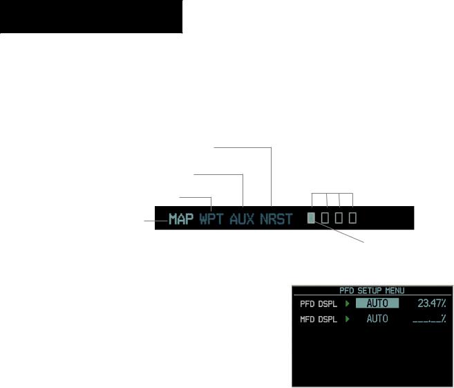
1.4MFD PAGE GROUPS
1.Turn the large FMS knob until the desired page group is selected.
2.Turn the small FMS knob to select pages within the group. See Figure 1-7.
Nearest Group
Auxiliary Page Group
Waypoint Page Group
Map Page Group
Number of Pages in Current
Group
Figure 1-7 Page Group Icon |
Selected Page |
1.5BACKLIGHTING
To manually adjust the backlight for the
PFD and MFD:
1.Press the MENU key on the PFD to display the PFD Setup Menu window.
2.Press the small FMS knob to activate the cursor. ‘PFD DSPL > AUTO’ is now high-
lighted. |
Figure 1-8 PFD Setup Menu Window |
3.Turn the small FMS knob to display the selection window.
4.Turn either FMS knob to select‘MANUAL’,then press the ENT key.
5.With the intensity value now highlighted, turn the small FMS knob to select the desired backlighting.
6.Turn the large FMS knob to highlight ‘MFD DSPL > AUTO’ and repeat steps 3 through 5.
1-8 |
Garmin G1000 Cockpit Reference Guide for the Mooney M20M & M20R |
SECTION 2
FLIGHT INSTRUMENTS
SECTION 2: FLIGHT INSTRUMENTS
1 |
16 |
15 |
14 |
|
|
|
13 |
2 |
|
|
12 |
|
|
|
11 |
3 |
|
|
10 |
4 |
|
|
9 |
|
|
|
|
5 |
|
|
8 |
|
|
|
|
6 |
|
|
7 |
1 |
NAV Frequency Window |
9 |
Turn Rate Indicator |
2 |
Airspeed Indicator |
10 |
Barometric Setting Box |
3 |
True Airspeed Box |
11 |
Vertical Speed Indicator |
4 |
Heading Box |
12 |
Altimeter |
5 |
Horizontal Situation Indicator |
13 |
Altitude Reference Box |
6 |
Outside Air Temperature Box |
14 |
COM Frequency Window |
7 |
System Time Box |
15 |
Navigation Status Bar |
8 |
Transponder Status Bar |
16 |
Slip/Skid Indicator |
Figure 2-1 Default PFD Information
Garmin G1000 Cockpit Reference Guide for the Mooney M20M & M20R |
2-1 |

SECTION 2
FLIGHT INSTRUMENTS
10
1
2
3
|
4 |
5 |
|
6 |
1 |
Traffic Annunciation |
|
7 |
Alerts Window |
2 |
Selected Heading Box |
|
8 |
Selected Course Box |
3 |
Inset Map |
|
9 |
Vertical Deviation/Glideslope Indicator |
4 |
BRG1 Information Window |
10 |
Marker Beacon Annunciation |
|
5 |
DME Information Window |
|
|
|
6 |
BRG2 Information Window |
|
|
|
|
|
|
|
Figure 2-2 Additional PFD Information |
|
|
||
|
Distance to Next Waypoint |
|
Desired Track to |
|
|
|||
|
|
Next Waypoint |
|
Current Track |
||||
|
|
|
||||||
|
Next Waypoint |
|
|
|
|
|
|
|
|
|
|
|
|
|
|
|
|
|
|
|
|
|
|
|
|
|
|
|
|
Figure 2-3 PFD Navigation Status Window |
|
|
|||
2-2 |
|
Garmin G1000 Cockpit Reference Guide for the Mooney M20M & M20R |
||||||
9
8
7
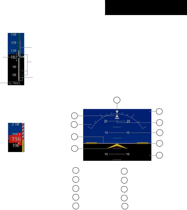
2.1AIRSPEED INDICATOR
Airspeed Trend
Vector
Actual Airspeed
Vspeed
References
Speed Ranges
True Airspeed
Box
Figure 2-4 Airspeed Indicator
Speed Indication
The indicated airspeed is displayed inside the black pointer. The pointer will become red upon reaching Vne.
Figure 2-5 Red Pointer at Vne
Speed Ranges
The color coded speed range strip denotes flaps operating range, normal operating range, and never exceed speed (Vne). A red range is also present for low speed awareness. Refer to the Airplane Flight Manual (AFM) for airspeed limitations and indicator markings.
Airspeed Trend Vector
The end of the trend vector displays approximately what the airspeed will be in 6 seconds if the current rate of acceleration/decelaration is maintained.
SECTION 2
FLIGHT INSTRUMENTS
Vspeed References
Vspeeds are set using the TMR/REFsoftkey. Glide, Vr, Vx and Vy are shown on the References window. When active (ON), the Vspeeds are displayed at their respective locations to the right of the airspeed scale.
2.2ATTITUDE INDICATOR
The Slip/Skid Indicator is located under the roll pointer and moves laterally away from the pointer to indicate lateral acceleration. One Slip/Skid indicator displacement is equal to one ball displacement when compared to a traditional slip/skid indicator.
|
10 |
|
|
1 |
|
|
9 |
|
|
|
|
2 |
|
|
8 |
|
|
|
|
3 |
|
|
7 |
|
|
|
|
|
|
|
6 |
4 |
|
|
|
|
|
|
5 |
1 |
Roll Pointer |
6 |
Aircraft Wing Tips |
2 |
Roll Scale |
7 |
Pitch Scale |
3 |
Horizon Line |
8 |
Slip/Skid Indicator |
4 |
Aircraft Symbol |
9 |
Sky Representation |
5 |
Land Representation |
10 |
Roll Index |
Figure 2-6 Attitude Indicator
Garmin G1000 Cockpit Reference Guide for the Mooney M20M & M20R |
2-3 |
SECTION 2
FLIGHT INSTRUMENTS
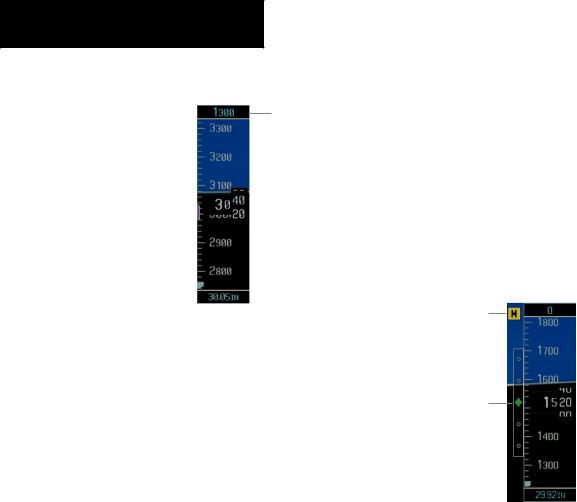
2.3ALTIMETER
Altitude Reference
Box
Altitude Trend |
|
Current Altitude |
||
|
||||
Vector |
|
|
|
|
Altitude Reference Bug |
|
|
|
Barometric Setting |
|
|
|
||
|
|
|
|
|
|
|
|
|
Box |
|
Figure 2-7 Altimeter |
|||
Altitude Reference Bug
The Altitude Reference Bug can be set to any desired altitude. The bug acts as a visual reference to indicate the desired altitude is approaching.
To set the altitude reference bug:
1.Turn the ALT knobs to set the altitude reference bug. The smallALT knob sets the hundreds and the large ALT knob sets the thousands. This altitude also appears in the altitude reference box above the altimeter.
Altitude Trend Vector
The end of the trend vector displays approximately what the altitude will be in 6 seconds if the current rate of vertical speed is maintained.
Barometric Setting Box
To set barometric pressure, turn the BARO knob to select the desired setting.
2.4VERTICAL DEVIATION/GLIDESLOPE INDICATOR
The Vertical Deviation/Glideslope Indicator appears when an ILS is tuned in the active NAV field.
2.5MARKER BEACON ANNUNCIATIONS
Marker Beacon
Annunciation
Vertical
Deviation/Glideslope
Indicator
Figure 2-8 Marker Beacon and Vertical Deviation
2-4 |
Garmin G1000 Cockpit Reference Guide for the Mooney M20M & M20R |
|
SECTION 2 |
|
|
FLIGHT INSTRUMENTS |
|
2.6 VERTICAL SPEED INDICATOR |
14 13 |
|
1 |
12 |
|
|
||
2 |
11 |
|
Vertical Speed Pointer |
||
|
||
3 |
10 |
|
4 |
9 |
|
|
||
5 |
8 |
|
|
||
6 |
7 |
|
|
||
Figure 2-9 Vertical Speed Indicator |
|
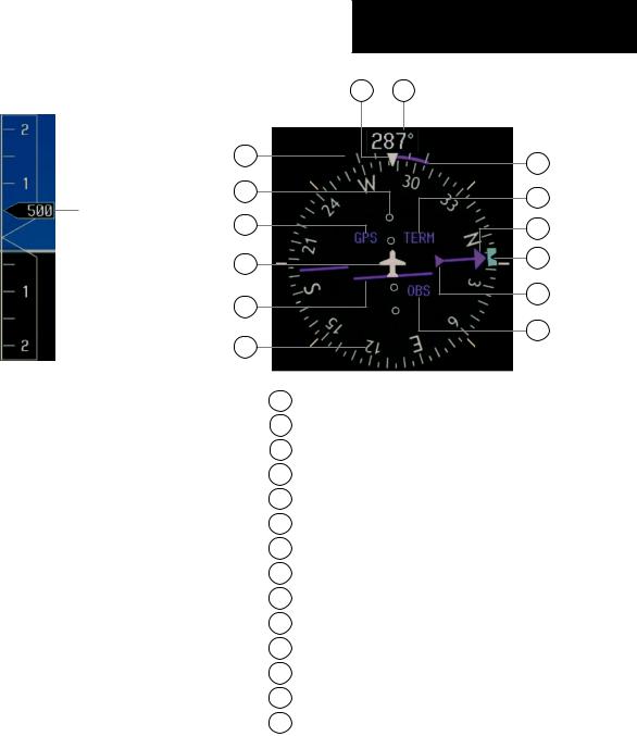
2.7HORIZONTAL SITUATION INDICATOR (HSI)
The HSI compass can be displayed as a 360° rose or 140° arc by pressing the PFD softkey, followed by the 360 HSI or the ARC HSI softkey.
1Turn Rate Indicator
2Lateral Deviation Scale
3Navigation Source
4Aircraft Symbol
5Course Deviation Indicator
6Rotating Compass Rose
7OBS Mode
8TO/FROM Indicator
9 Heading Bug
10Course Pointer
11Flight Phase
12Turn Rate and Heading Trend Vector
13Heading
14Lubber Line
Figure 2-10 Horizontal Situation Indicator
Garmin G1000 Cockpit Reference Guide for the Mooney M20M & M20R |
2-5 |
SECTION 2
FLIGHT INSTRUMENTS
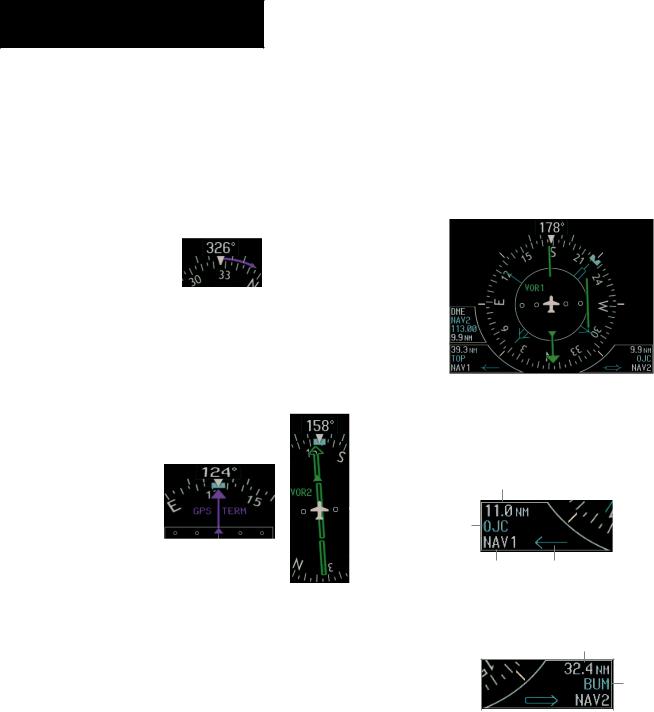
Turn Rate Indicator and Heading Trend Vector
Each tick mark is at 9 (half standard rate tick mark) and 18 (standard rate tick mark) degrees to the left and right of the lubber line. A wide magenta line displays the current turn rate, up to 24 degrees. A magenta arrowhead appears at 25 degrees. This trend vector provides the pilot with a prediction of what the heading will be in 6 seconds at the present turn rate.
Figure 2-14 Turn Rate Indicator and Heading Trend Vector
Course Pointer
The course pointer is a single line arrow (GPS, VOR1 andLOC1)ordoublelinearrow(VOR2andLOC2)which points in the direction of the set course.
|
|
|
|
|
|
|
|
|
|
|
|
Course |
|
Deviation |
|
Lateral |
|
Deviation |
|
||||
|
|
||||||
Scale |
TO/FROM Indicator |
||||||
Figure 2-15 Arc CDI and Compass Rose CDI
Bearing Pointers and Information Windows
Pressing the PFD softkey provides access to the BRG1 and BRG2 softkeys. The BRG1 pointer is a single line pointer. The BRG2 pointer is a double line pointer.
DME |
Bearing 1 |
|
|
||
Information |
Bearing 2 |
||||
Window |
Pointer |
||||
|
|
|
|
Pointer |
|
|
|
|
|
|
|
|
|
|
|
|
|
|
|
|
|
|
|
|
|
|
|
Bearing 1 |
Bearing 2 |
||
Information |
Information |
||
Window |
Window |
||
Figure 2-14 HSI with Bearing Information
Distance to
Bearing Source
Waypoint
Identifier
Bearing Pointer
Source Icon
Figure 2-15 BRG1 Information Window
Course Deviation Indicator (CDI)
The CDI scale automatically adjusts to the current phase of flight (enroute 5.0 nm, terminal area 1.0 nm, or approach 0.3 nm). Scaling may be selected manually from the MFD System Setup Page.
Distance to
Bearing Source
Waypoint
Identifier
|
|
|
|
Pointer |
Bearing |
||
Icon |
Source |
||
|
Figure 2-16 BRG2 Information Window |
2-6 |
Garmin G1000 Cockpit Reference Guide for the Mooney M20M & M20R |
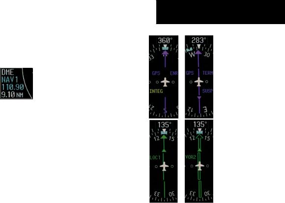
DME Radio (optional)
To display the DME Information Window, press the PFD softkey followed by the DME softkey.
Figure 2-17 DME Information Window
Navigation Source
To change between navigation sources:
1.Press the CDI softkey to change from GPS to VOR1/LOC1.
2.Press the CDI softkey again to change from VOR1/LOC1 to VOR2/LOC2.
3.Press the CDI softkey a third time to return to GPS.
When using GPS as the navigation source, the following may appear:
•INTEG – RAIM is not available
•WARN – GPS detects a position error
•SUSP – Displayed when in OBS Mode indicating GPS navigation is suspended.
SECTION 2
FLIGHT INSTRUMENTS
Figure 2-18 GPS INTEG, GPS SUSP, LOC1 and VOR2
To enable/disable OBS mode while navigating with GPS:
1.Press the OBS softkey to select OBS Mode.
2.Turn the CRS knob to select the desired course TO/FROM the waypoint.
3.Pressthe OBS softkeyagaintoreturntonormal operation.
Garmin G1000 Cockpit Reference Guide for the Mooney M20M & M20R |
2-7 |

SECTION 2
FLIGHT INSTRUMENTS
.
This page intentionally left blank.
2-8 |
Garmin G1000 Cockpit Reference Guide for the Mooney M20M & M20R |
SECTION 3: ENGINE INDICATION
SYSTEM (EIS)
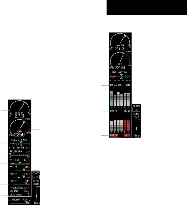
3.1ENGINE DISPLAY
In all cases green indicates normal operation, yellow indicates caution, and red indicates warning.
Mooney M20R Engine displays are shown in this section. TheM20Mdisplaysaresimilarwiththeexceptionof showing the Turbine Inlet Temperature (TIT).
Pressing the ENGINE softkey makes available the LEAN and SYSTEM softkeys which in turn provide access the Lean Page and the System Page, respectively.
Manifold
Pressure
Gauge
RPM Gauge
Fuel Quantity
Indicator
Fuel Flow
Indicator
Oil Pressure
Indicator Oil Temperature
Indicator
Cylinder Head
Temperature
Indicator
Voltmeter
Ammeter
Figure 3-1 M20R Default Engine Page
In aircraft with the extended range 55 gallon tanks option, the fuel quantity will still show 45 gallons when full.
SECTION 3 – ENGINE
INDICATION SYSTEM (EIS)
3.2LEAN ENGINE DISPLAY
Fuel Flow
Readout
Exhaust Gas
Temperature
Bar Graph
EGT Readout
For Selected
Cylinder
Cylinder Head
Temperature
Bar Graph
CHT Readout
For Selected
Cylinder
Figure 3-2 M20R LEAN Engine Page
Cylinder Select
The CYL SLCT softkey can be utilized to obtain information about a particular cylinder.
The CYL SLCT softkey becomes disabled when a particular cylinder turns yellow or red, until the temperature decreases and returns to normal or when the ASSIST softkey is pressed.
Pressing the ASSIST softkey causes the first cylinder that peaks to become hightlighted and information for that cylinder to be displayed.
Any exceedance of default Engine Page parameters, whileviewingtheLeanEnginePage,willcausethedisplay to automatically switch back to the default Engine Page.
Garmin G1000 Cockpit Reference Guide for the Mooney M20M & M20R |
3-1 |
Loading...