


INSTALLATION AND OPERATION MANUAL
GARLAND INDUCTION
BUILT-IN LINE
DUAL-ZONE COOKERS
with RTCSmp TECHNOLOGY Real-time Temperature Control System multi-point sensing
CE models comply with the latest European Norms:
EN 60335-1, EN 60335-2-36, EN 62233 (EMC/EMV)
North American models: ETL listed in compliance with UL 197, CSA C22.2 No.109, NSF-4
Complies with FCC part 18, ICES-001
WARNING
IMPROPER INSTALLATION, ADJUSTMENT, ALTERATION, SERVICE OR MAINTENANCE CAN CAUSE PROPERTY DAMAGE, INJURY, OR DEATH. READ THE INSTALLATION, OPERATING AND MAINTENANCE INSTRUCTIONS THOROUGHLY BEFORE INSTALLING OR SERVICING THIS EQUIPMENT
Models:
SH DU IN 7000 (2x3500 / 7kW)
SH DU IN 10000 (2x5000 / 10kW)
PLEASE READ ALL SECTIONS OF THIS MANUAL AND RETAIN FOR FUTURE REFERENCE.
THIS PRODUCT HAS BEEN CERTIFIED AS COMMERCIAL COOKING EQUIPMENT AND MUST BE INSTALLED BY PROFESSIONAL PERSONNEL AS SPECIFIED
INSTALLATION AND ELECTRICAL CONNECTION MUST COMPLY WITH CURRENT CODES IN YOUR REGIION:
IN CANADA – THE CANADIAN ELECTRICAL CODE PART 1 AND / OR LOCAL CODES.
IN USA – THE NATIONAL ELECTRICAL CODE ANSI / NFPA – CURRENT EDITION.
FOR YOUR SAFETY
DO NOT STORE OR USE GASOLINE OR OTHER FLAMMABLE VAPORS OR LIQUIDS IN THE VICINITY OF THIS OR ANY OTHER APPLIANCE
Users are cautioned that maintenance and repairs must be performed by a Garland authorized service agent using only genuine Garland replacement parts. Garland will have no obligation with respect to any product that has been improperly installed, adjusted, operated or not maintained in accordance with national and local codes and/or installation instructions provided with the product or any product that has its serial number defaced, obliterated or removed, and/or which has been modified or repaired using unauthorized parts or by unauthorized service agents. For a list of authorized service agents and/or genuine replacement parts, please visit our website at www.garland-group.com (USA and Canadian customers) or www.manitowocfoodservice.com (international customers). The information contained herein, including design and part specifications, may be superseded and is subject to change without notice.
Visit our Video Gallery at
www.Garland-Group.com
Part # 4532285 Rev 4 (4/29/14) © 2013 Garland Commercial Ranges Limited
Installation and Operation Manual |
RTCSmp Induction Built-In Line Dual Zone Cookers |
|
|
|
|
WARRANTY
Our warranty statements for induction products are available on-line. Please visit our website at www.garland-group.com/minisite/service to download the latest revision. If you might have any questions, please contact Garland.
USING THIS MANUAL
This manual contains important information regarding safety, installation, operation, maintenance, and troubleshooting. They must be read entirely and carefully by the installers and operators before the equipment is installed and taken into operation. This manual must always be available for reference at the place of operation.
Throughout this manual, the induction unit type “RTCSmp Dual Install-Line” is referred to as “induction unit”.
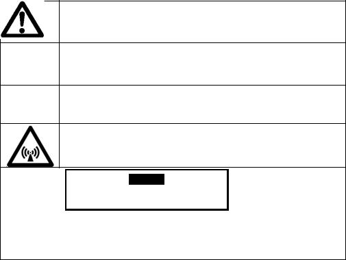
DESCRIPTION OF WARNING SYMBOLS
This symbol alerts you to a hazardous situation that WILL or COULD cause serious bodily harm or death. Be alert and implement relevant safety precautions.
This dangerous voltage warning symbol indicates a risk of electric shock and hazards from dangerous voltage.
This symbol alerts a hazardous situation, which if not avoided, COULD
CAUTION cause minor to moderate personal injury or property damage. The relevant safety precautions MUST be implemented at all times.
Electromagnetic field.
Warning
Risk of fire or electric shock
Do not open
To reduce the risk of fire or electric shock, do not remove or open cover.
No user serviceable parts inside. Refer servicing to qualified personnel.
CONTACTS
Garland Commercial Ranges Ltd.
1177 Kamato Road, Mississauga, Ontario, Canada. L4W 1X4
T: 1-905-624-0260 | F: 1-905-624-5669 | www.garland-group.com
USA Sales, Parts and Service |
1-800-424-2411 |
Canadian Sales |
1-888-442-7526 |
Canada or USA Parts/Service |
1-800-427-6668 |
International Sales and Service www.ManitowocFoodservice.com
2 |
Part # 4532285 Rev 4 (4/29/14) |

Installation and Operation Manual RTCSmp Induction Built-In Line Dual Zone Cookers
CONTENTS
WARRANTY ....................................................................................................................................................... |
2 |
USING THIS MANUAL ....................................................................................................................................... |
2 |
DESCRIPTION OF WARNING SYMBOLS........................................................................................................... |
2 |
CONTACTS......................................................................................................................................................... |
2 |
1 Safety Requirements .............................................................................................................. |
4 |
|
1.1 |
Risk Involved By Disregarding Safety Information............................................................................................. |
4 |
1.2 |
Safety Instructions for Operator ............................................................................................................................... |
4 |
1.3 |
Improper Use of the Equipment............................................................................................................................... |
5 |
1.4 |
Unauthorized Modification and Use of Spare Parts........................................................................................... |
5 |
1.5 |
Pan Detection ................................................................................................................................................................. |
5 |
1.6 |
Cooking Zone Monitoring.......................................................................................................................................... |
5 |
2 Components and Features ..................................................................................................... |
6 |
|
2.1 |
Application ...................................................................................................................................................................... |
6 |
2.2 |
Components Included ................................................................................................................................................. |
6 |
2.3 |
Features ............................................................................................................................................................................ |
6 |
3 Dimensions and Technical Specifications ............................................................................. |
7 |
|
3.1 |
Rating Plate...................................................................................................................................................................... |
7 |
3.2 |
Nomenclature and Models......................................................................................................................................... |
7 |
3.3 |
Dimensions and Weights............................................................................................................................................ |
7 |
3.4 |
Electrical Specifications ............................................................................................................................................... |
7 |
3.5 |
Operating Conditions .................................................................................................................................................. |
7 |
3.6 |
Compliances.................................................................................................................................................................... |
7 |
4 |
Installation .............................................................................................................................. |
|
8 |
|
|
4.1 |
Location ............................................................................................................................................................................ |
|
8 |
|
4.2 |
Ventilation........................................................................................................................................................................ |
|
8 |
|
4.3 |
Dimensions and Installation ...................................................................................................................................... |
9 |
|
|
|
4.3.1 Built-In Induction Unit Installation.............................................................................................................. |
9 |
|
|
|
4.3.1.1 Dimensions: Dual Zone RTCSmp Built-In SHDUIN7000 /10000 |
9 |
|
|
|
4.3.1.2 Top-Mount / Flush-Mount and Dimensions |
9 |
|
|
|
4.3.1.3 Compartment Protection and Clearance |
10 |
|
|
|
4.3.1.4 Parallel Installation and Clearance |
10 |
|
|
|
4.3.1.5 |
Installation Steps |
11 |
|
|
4.3.2 Control Unit Installation ............................................................................................................................... |
12 |
|
|
|
4.3.2.1 |
Front-Mount |
12 |
|
|
4.3.2.2 |
Back-Mount |
12 |
|
|
4.3.2.3 Dimensions: Control Unit RTCSmp Built-In SHDUIN |
13 |
|
|
|
4.3.3 Air Intake Kit Installation .............................................................................................................................. |
13 |
|
|
|
4.3.3.1 |
Components |
13 |
|
|
4.3.3.2 |
Installation Steps |
14 |
|
4.4 |
Electrical Installation................................................................................................................................................... |
15 |
|
5 |
Function Test......................................................................................................................... |
|
16 |
|
6 |
Operating Instructions ......................................................................................................... |
17 |
||
|
6.1 |
Proper Induction Cookware..................................................................................................................................... |
17 |
|
|
6.2 |
Proper Placement of Cookware on Dual Hobs .................................................................................................. |
18 |
|
|
6.3 |
Power Control............................................................................................................................................................... |
|
18 |
|
6.4 |
No Pan No Heat............................................................................................................................................................ |
|
19 |
|
6.5 |
When Unit is Not In Use............................................................................................................................................. |
19 |
|
7 |
Cleaning................................................................................................................................. |
|
20 |
|
8 |
Maintenance.......................................................................................................................... |
|
21 |
|
9 |
Important Rules .................................................................................................................... |
|
21 |
|
10 |
Troubleshooting ................................................................................................................... |
|
22 |
|
|
10.1 |
Common causes for induction unit failure ......................................................................................................... |
22 |
|
|
10.2 |
Problems and Possible Causes................................................................................................................................ |
23 |
|
|
10.3 |
Indicator Lamp Flashes at Intervals (for Operators)......................................................................................... |
24 |
|
|
10.4 |
Troubleshooting with Error Codes (for Service Technicians)........................................................................ |
25 |
|
Part # 4532285 Rev 4 (4/29/14) |
3 |

Safety Requirements |
RTCSmp Induction Built-In Line Dual Zone Cookers |
|
|
|
|
1Safety Requirements
WARNING |
This product contains chemicals known to the State of California to cause cancer. |
||
|
|
Installation and servicing of this product could expose you to airborne particles of glass |
|
|
|
wool / ceramic fibers. Inhalation of airborne particles of glass wool / ceramic fibers is |
|
|
|
known to the State of California to cause cancer. |
|
IMPORTANT |
Warning labels mounted directly on the induction unit must be observed at all times and |
||
|
|
kept in a fully legible condition. |
|
IMPORTANT |
To ensure your work environment is safe, you must follow all of the safety instructions |
||
|
|
contained in this manual, the existing national regulations for accident prevention with |
|
|
|
electrical systems, as well as any relevant company-specific safety instructions. |
|
|
|
|
|
|
|
The induction unit should only be used if and only if the |
|
|
|
installation of the electrical system is fitted by an approved |
|
|
|
installation contractor in accordance with specific national and |
|
|
|
local regulations. |
|
|
|
|
|
1.1Risk Involved By Disregarding Safety Information
Disregarding the safety instructions may cause harm to people, the surroundings, and the induction unit. Garland is not responsible for any damages or personal injury caused by failure to observe the safety requirements. Risks involved when disregarding safety precautions may include:
Death or injury caused by electric shock.
Injury due to burns from contacting overheated cooking surface, cookware, or oil and grease.
Damage to the induction unit caused by using unsuitable cookware.
1.2Safety Instructions for Operator
Please follow the following rules to avoid personal injuries and property damages:
When the unit is in use, heat transfers from cookware to the glass-top; the glass-top can become hot. To avoid burn injuries, do not touch the heating area when the unit is in use.
The induction unit heats up cookware and cooks food quickly. Do not leave an empty pan on the unit and do not leave the unit unattended during operation.
If the glass-top is cracked or broken, switch off the induction unit immediately and if possible and safe, disconnect it from the power supply. Do not touch any parts inside the induction unit.
Persons with cardiac pacemakers should consult their doctors whether they are safe near an induction unit.
If the power cord is damaged, have it replaced immediately by an approved service technician.
Ensure no liquid can enter into the induction unit. Do not let water or food overflow the cooking area. Do not use hoses to clean or power wash the induction unit or its vicinity.
Do not put any other items on the glass-top except non-empty induction cookware.
oDo not leave any object such as paper, cardboard, or cloth between the cookware and the cooking surface, as this might start a fire.
oMetallic objects are heated up very quickly when placed on the induction unit when the unit is in use. Do not place any objects such as closed cans, aluminum foil, cutlery, jewelry, or watches on the induction unit when the unit is in operation.
4 |
Part # 4532285 Rev 4 (4/29/14) |
Safety Requirements |
RTCSmp Induction Built-In Line Dual Zone Cookers |
|
|
|
|
oDo not place credit cards, phone cards, tapes, or any objects sensitive to magnetism on the cooking surface.
oDo not place any vessels made of aluminum or plastics on the glass-top.
The induction unit has an internal air-cooling system. Do not block the air intake and exhaust openings with objects such as cleaning cloths or containers. Any obstruction to the air intake and exhaust could cause the unit to overheat and to switch off.
Switch the unit OFF if you take the cookware away for a while. This will prevent the heating process to start automatically and unintentionally when a pan is placed back on the heating area. If any person needs to use the induction unit, he/she will have to turn the unit ON intentionally.
A dirty air intake filter blocks the fresh air intake. Clean the air intake filter at least once a week or as often as necessary. Garland’s Air Intake Filter, included in the Air Intake Kit, is dishwasher-safe.
Use only induction suitable cookware with proper sizes and made of proper material. The induction suitable cookware should also be in good condition without any uneven, arched or partially detached bottoms.
1.3Improper Use of the Equipment
The reliability of the induction unit can only be guaranteed when it is used properly. The induction unit must always be operated within the limits provided in the technical specifications. Please also refer to chapter 9 Important Rules for using induction equipment.
1.4Unauthorized Modification and Use of Spare Parts
Please contact Garland if you intend to make any changes on the induction unit. For safety reasons, always use genuine parts and accessories approved by Garland. Any unauthorized modification as well as any installation of unapproved components will void all warranty.
1.5Pan Detection
Energy is transferred to cookware when the induction system detects a suitable pan on the heating area. The green indicator light signals to communicate the Pan Detection process:
When the unit is ON without any pan on the hob, the green indicator light flashes; the unit is in pan detection mode.
As soon as a pan is put on the hob, the heating process is engaged and the indicator light stops flashing and remains bright. However, the indicator light will keep flashing if the unit is not detecting any pan or an unsuitable pan is placed on the hob.
NOTE: Pan with a bottom diameter smaller than 5”(12 cm) is not detected by the system.
1.6Cooking Zone Monitoring
Each cooking zone is monitored by multiple temperature sensors beneath the glass-top. The sensors can detect overheated empty pans or overheated oil and grease. When this occurs, the system stops the energy supply to the pan. You must turn the unit off and let it cool down before restarting it.
To avoid burn injuries, do not touch the unit when a pan is CAUTION overheated and take all the necessary precautions when
removing the overheated pan.
Part # 4532285 Rev 4 (4/29/14) |
5 |
Components and Features |
RTCSmp Induction Built-In Line Dual Zone Cookers |
|
|
|
|
2Components and Features
2.1Application
The RTCSmp Dual Install-Line units are specially engineered as built-in cooking equipment for closed counters. The cookers can be used for many applications such as cooking, warming, flambéing, and brazing. To guarantee the reliability and performance of the induction equipment, please observe all safety, installation, and operation requirements mentioned in this manual.
2.2Components Included
1 Induction Generator with Built-in Frame and Ceran Glass-Top.
2 Control Units and 2 RJ-45 cables, each cable is 36” (914mm) long.
1 Air Intake Kit (part number 95000020 for dual models)
Installation and Operation Manual.
2.3Features
Garland offers two power ratings— 7kW and 10kW— for the RTCSmp Dual Install-Line induction units. Built with a robust construction, the induction units are compact and powerful with the revolutionary RTCSmp-Technology (Realtime Temperature Control System with Multi-Point sensing). The RTCSmp Technology monitors the energy supply, the state of the induction coil, power board, CPU, and the cooking zones in realtime. The essential features are:
Drop-in, flush mounted design with CrNi-Steel body below counter.
High impact Ceran glass-top.
Control units are mounted separately from the built-in unit. Easy to connect with the RJ-45 cables (provided).
Integrated cooling fan keeps electronics cool.
Compact and flat profile with powerful electronics.
Thermostatically controlled overheat sensors shut off the unit preventing damage from pans cooking dry.
Instant energy transmission to the cookware only, not to the surrounding air.
Electronic output limitation continually monitors the energy transfer to the cookware, ensuring the most efficient energy transfer possible.
Easy to install.
Simple to operate. Adjust cooking power level simply by turning the knob.
6 |
Part # 4532285 Rev 4 (4/29/14) |

Dimensions and Technical Specifications |
RTCSmp Induction Built-In Line Dual Zone Cookers |
|
|
|
|
3Dimensions and Technical Specifications
3.1Rating Plate
The rating plate specifies important information such as the model number, serial number, and electrical specifications. The rating plate is affixed to the unit’s housing, close to the mains power connection on the unit.
3.2Nomenclature and Models
Series |
Dual Hobs |
Built-In |
Power (Watt) |
|
Models |
SH = |
DU |
IN = |
7000 (2x 3500) |
|
SH DU IN 7000 (2x 3500 / 7kW) |
Slim Hob |
|
Built-In Line |
10000 (2x 5000) |
|
SH DU IN 10000 (2x 5000 / 10kW) |
3.3 |
Dimensions and Weights |
|
|
|
||
|
|
|
Glass Area Only |
Glass-Top with Frame |
Shipping |
Net |
|
|
|
(width x depth) |
(width x depth) |
Weight |
Weight |
|
|
7kW Model |
12.60” x 22.83” (320 x 580 mm) |
15.12” x 25.35” (384 x 644 mm) |
25kg/55.1lb |
23kg/50.7lb |
|
|
|
|
|
|
|
|
|
10kW Model |
12.60” x 22.83” (320 x 580 mm) |
15.12” x 25.35” (384 x 644 mm) |
27kg/59.5lb |
25kg/55.1lb |
|
|
|
|
|
|
|
3.4 |
Electrical Specifications |
|
|
||
|
|
|
Voltage |
Power |
Conductor Size |
|
|
|
208 V AC / 3Ph / 60Hz |
7000 W (2x 3500W) / 22A |
AWG 10 |
|
|
7kW Model |
|
|
|
|
|
400 V AC / 3Ph / 50Hz |
7000 W (2x 3500W) / 11A |
1.5mm2 |
|
|
|
|
440 V AC / 3Ph / 50Hz |
7000 W (2x 3500W) / 10A |
1.5mm2 |
|
|
|
208 V AC / 3Ph / 60Hz |
10000 W (2x 5000W) / 30A |
AWG 8 |
|
|
|
|
|
|
|
|
10kW Model |
400 V AC / 3Ph / 50Hz |
10000 W (2x 5000W) / 16A |
2.5mm2 |
|
|
|
440 V AC / 3Ph / 50Hz |
10000 W (2x 5000W) / 15A |
2.5mm2 |
3.5 |
Operating Conditions |
|
|
|
|
|
Max. Tolerance of Nominal Supply Voltage |
+6 /-10 % |
|
|
|
|
|
|
|
|
Supply frequency |
50/60 Hz |
|
|
|
|
|
|
|
|
Ingress Protection class |
IP X0 |
|
|
|
|
|
|
|
|
Minimal Diameter of Induction Pan |
5” (12cm) |
|
|
|
|
|
|
|
|
Maximum Ambient Temperature |
In Storage |
> -4°F to +158°F (-20°C to +70°C) |
|
|
|
|
|
|
|
|
In Operation >+ 41°F to +104°F (+5°C to +40°C) |
|
|
|
|
|
|
|
|
Maximum Relative Air Humidity |
In Storage |
> 10% to 90% |
|
|
|
|
|
|
|
|
In Operation > 30% to 90% |
|
|
|
|
|
|
|
|
Clearance from Materials |
Min. 1.18” / 30mm |
|
|
|
|
||
|
|
Maximum air flow: 70.63cfm/120m3 per hour and min. opening: 10.075in2/6500mm2 is required. |
||
3.6Compliances
North American models:
ETL listed in compliance with UL 197, CSA C22.2 No.109, NSF-4. Complies with FCC part 18, ICES-001
CE models comply with the latest European Norms: EN 60335-1, EN 60335-2-36, EN 62233 (EMC/EMV)
Part # 4532285 Rev 4 (4/29/14) |
7 |
Installation |
RTCSmp Induction Built-In Line Dual Zone Cookers |
|
|
|
|
4Installation
IMPORTANT
Kitchen designers and installation contractors are responsible for designing and installing correctly the appropriate support structures and ventilation system for the cooking equipment.
When designing kitchen cabinets for the induction equipment, please take into account all installation requirements, including factors such as: ease of electrical installation, size of the power conductor, and length of the wires.
The installation, including electrical installation, must be carried out by registered installation contractors only. The contractors are responsible for interpreting all instructions correctly and performing the installation in compliance with national and local regulations. The warning signs and rating plates on the cooking equipment must strictly be followed.
Read ALL SECTIONS carefully, comply with all requirements listed and ensure all inspection is done by qualified personnel.
Refer to the technical data given in chapter 3 Dimensions and Technical Specifications.
Induction equipment that is not installed correctly will have warranty voided. See Warranty, p.2.
4.1Location
The induction unit must be installed securely in closed counters. IMPORTANT: Allow easy access to the unit, the air intake filter, and the cable connections for maintenance and service.
The induction unit must be installed securely on a leveled and even counter surface.
Do not place the induction unit on or near a hot surface or any heat producing equipment such as an oven or a deep fryer.
Protect the induction unit from steam if the unit is placed next to high steam emitting equipment such as pasta cookers, steamers, and water bath.
Allow easy access to the control knobs and ensure the LED lights are not obstructed.
Keep the induction unit away from combustible materials, vapors or liquids.
4.2Ventilation
Proper cool air intake and ventilation is essential to the reliability and functioning of the induction unit. Please ensure all requirements listed below are met:
This induction unit is equipped with an internal air cooling system. Ensure the air supply and air exhaust outlets are not blocked. CLEARANCE: minimum 1.18” (30mm).
The maximum air flow is 70.63cfm (120m3 per hour) and therefore a minimal opening of 10.075 square inches (6500 mm2) is required.
An optimal air intake must not be restricted by the installation.
When installing the built-in unit, ensure the intake air and exhaust air are conducted separately. The intake air and exhaust air must not mix. To avoid build-up of hot exhaust air inside the cabinet, draw the exhaust air out of the cabinet. Build up of hot exhaust air will cause the induction unit to reduce power or to switch-off.
Ensure the Air Intake Kit is installed properly to guarantee cool air supply to the induction unit.
Ensure the induction unit does not take in hot ambient air from other surrounding units and appliances, especially when the unit is installed close to heat generating equipment such as fryers or ovens.
The air intake temperature must not exceed 104 F (40 C).
8 |
Part # 4532285 Rev 4 (4/29/14) |

Installation |
RTCSmp Induction Built-In Line Dual Zone Cookers |
|
|
|
|
It is highly recommended that an exhaust fan be installed into the cabinet at an appropriate location. This will force hot air out the cabinet and away from the induction unit. Consult an electrical or installation expert for the most appropriate location to install a cabinet exhaust fan.
4.3Dimensions and Installation
4.3.1Built-In Induction Unit Installation
4.3.1.1Dimensions: Dual Zone RTCSmp Built-In SH DU IN 7kW / 10kW
FRONT |
FRONT |
4.3.1.2Top-Mount / Flush-Mount and Dimensions
There are two methods to install the built-in unit—top-mount (A) or flush-mount (B). The counter surface cut-out dimensions are different for these two methods.
i
A |
B |
ii |
iii
TOP-MOUNT — cut-out dimensions on the counter surface:
345 x 605mm [13.58” x 23.82”]
FLUSH-MOUNT — cut-out dimensions:
(i)Opening for flange:
minimum– 384.5 x 644.5mm [15.14 “ x 25.37”] maximum– 385.6 x 645.6mm [15.18” x 25.41”]
(ii)Depth for flange: 2mm [0.079”]
(iii)Body clearance: 345 x 605mm [13.58” x 23.82”]
Part # 4532285 Rev 4 (4/29/14) |
9 |
 Loading...