


Ganz ZC-DW5212NXA, ZC-DWN5212NXA, ZC-DW5550NXA, ZC-DW5550NXAT, ZC-DN5212NXA User Manual
...
INSTRUCTION MANUAL
WITH

Thank you for your purchase of this product.
Before operating this product, please read this instruction manual carefully.
After you have read this manual, store it in a safe place for future reference.
CONTENTS 


PRODUCT FEATURES.................................................................................... |
EG-2 |
SAFETY PRECAUTIONS................................................................................. |
EG-3 |
PART NAMES................................................................................................... |
EG-4 |
INSTALLATION AND ADJUSTMENT.............................................................. |
EG-5 |
MODEL DESCRIPTION.................................................................................. |
EG-10 |
SPECIFICATIONS........................................................................................... |
EG-11 |
PRODUCT FEATURES |
|
•High-resolution surveillance camera with a new built-in 1/3-type CCD. It delivers clear images at a horizontal resolution of 700 TVL by using a new high-resolu- tion CCD and image processing technology.
•Integrated varifocal lens allows for versatile application and easy installation.
•Surface or embedded installation.
•Manual pan/tilt/rotation mechanism.
•12 V DC/24 V AC auto switching power supply.
•The new 12,600 times Wide Dynamic Range (WDR) processing allows sharp images even if the pictures are shot in mixed indoor/outdoor scenes with backlight.
•New Easy Focus function helps adjust the lens focus by edge enhancement, focus level bar, and screen view zoom-up / down.
•The Color Bar Output function enables the checking and adjustment of cable signal levels and monitoring of the image quality.
•The Defog function provides high-quality images with automatically enhanced contrast in an environment with poor visibility, such as fog, mist, rain, and snow.
•The 3D-Digital Noise Reduction (3D-DNR) function realizes low noise and high sensitivity.
•The OSD settings can be dynamically switched using the Profile Switching function. With these functions, two preset profiles can be switched with each other when a Mode Selection terminal has been controlled or Day/Night switching has been made. A combination of profiles can be selected according to surveillance conditions.
•Day/Night function provides a high-sensitivity black and white image in low light conditions (e.g., night time) by automatically switching the camera to black and white mode. The camera is automatically switched to color mode in brighter light conditions (e.g., day time).
•This product offers additional functions such as Stabilizer, Privacy Mask, and Motion Detection functions.
EG-2

SAFETY PRECAUTIONS 


The installation should be made by a qualified service person and should conform to all local codes. For this device provided no power switch, the installation shall be carried out in accordance with the rules of the country or the region in which the equipment is to be installed.
This symbol indicates that there is a possibility of death or damage to operator or others.
(1)Use only 24V AC power supply marked class 2 or +12V DC regulated power supply marked class 2.
(2)To prevent fire or electrical shock, UL listed class 2 wiring should be used for the 12V DC or 24V AC input terminal.
(3)Be sure to connect each lead to the appropriate terminal. Wrong connection may cause malfunction and/or damage to the video camera.
(4)Never attempt to disassemble or modify the camera.
(5)If an abnormality should occur, immediately turn off the power and consult your dealer.
(6)To prevent fire or electric shock, do not expose this product to rain or moisture.
This symbol indicates that there is a possibility of injury or damage to equipment.
(1)Do not attempt to aim the camera at the sun or other extremely bright objects that cause smear to appear irrespective of whether the camera is operating or not. This can damage the CCD (Charge Coupled Device).
(2) Do not place the camera in the following locations.
1Locations subject to extremely high or low temperatures. (Operating temperature range: -10°C to +50°C {14°F to 122°F}) (Storage temperature range: -20°C to +60°C {-4°F to 140°F})
2Locations subject to high levels of humidity and dust. (Operating humidity range: max 85% {No condensation})
(Storage humidity range: max 95% {No condensation})
3 Locations where there are large amounts of water vapor and steam.
(3)Ensure the location selected is sufficiently strong enough to support the weight of the camera and is free from vibration.
(4)When this camera is installed near equipment that emits a strong electromagnetic field, some irregularity such as noise on the monitor screen may happen.
(5)Do not allow the camera to be subjected to strong impacts or shocks. The camera could be damaged by improper handling or storage.
This device complies with Part 15 of the FCC Rules. Operation is subject to following two conditions:
(1)This device may not cause harmful interference.
(2)This device must accept any interference received, including interference that may cause undesired operation.
Industry Canada’s Compliance Statement
This Class A digital apparatus complies with Canadian ICES-003.
Cet appareil numérique de la classe A est conforme à la norme NMB-003 du Canada.
EG-3
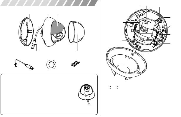
PART NAMES
Exterior
Surface mount cover Body cover Inner cover
Video relay cable Camera body |
Dome cover |
Accessories
|
|
M4 x 20 2 pcs. |
Service monitor cable |
Adapter ring |
Self-tapping screws |
Removing and attaching the cover
•Dome cover
To remove : Pull the cover away.
To attach : Insert the cover and push it gently until you hear a click.
•Body cover
To remove : Insert a flat-bladed screwdriver into the groove between the camera body and the body cover, then twist the screwdriver.
To attach : Align the corrugations on the camera body
and body cover, then push until you hear a click.
Flat-bladed screwdriver
Camera body interior
1 Lens |
4 Menu Operation Switch |
|
5 Video output connector |
2 Focus/ |
for service monitor |
|
|
View angle |
7 Termination |
adjustment lever |
resistance switch (with |
|
communication function) |
|
8 B/W Fix terminal/Mode |
|
Selection terminal |
3 Power input |
|
terminal |
9 RS485 communication |
|
terminal (with |
|
communication function) |
|
6 Video relay cable |
1Lens |
|
|
|
2 |
∞ |
|
N : Focus adjustment lever |
|
|||
|
W |
|
T : View angle adjustment lever |
|
|
||
Positioning of the lens body angle/focus adjustment lever varies depending on the lens. Please refer to the above guides for operation marked on the side of the levers while using the product.
3Power input terminal
4Menu Operation Switch
5Video output connector for service monitor
6Video relay cable
7Termination resistance switch (with communication function)
8B/W Fix terminal/Mode Selection terminal
9RS485 communication terminal (with communication function)
EG-4
 Loading...