


Pub. 42004-488C
G A I - T R O N I C S ® C O R P O R A T I O N |
|
A H U B B E L L C O M P A N Y |
|
Model LE300-IP |
|
Page/Party® Line Extender |
|
T A B L E O F C O N T E N T S |
|
Confidentiality Notice ..................................................................................................................... |
1 |
General Information....................................................................................................................... |
1 |
Model LE300-IP Line Extender and Sub-Component Details ........................................................... |
2 |
Model LE300-IP Internal View ............................................................................................................................ |
3 |
Audio Termination Connection Module ............................................................................................................... |
4 |
Input/Output (I/O) Termination Connection Module............................................................................................ |
4 |
Main PCBA........................................................................................................................................................... |
5 |
Features and Functions.................................................................................................................. |
6 |
Page Line Audio Transmission.............................................................................................................. |
6 |
Page Line Audio Monitoring Output .................................................................................................... |
7 |
Page Line Audio Detect Output Contact .............................................................................................. |
8 |
Page Line FSK Data Transmission (SmartSeries Systems) ................................................................ |
8 |
Page Line 50 kHz VLC Transmission................................................................................................... |
9 |
Page Line Ground Fault Detection........................................................................................................ |
9 |
Page Line Ground Fault Re-generation.............................................................................................. |
10 |
Page Line Ground Fault Output Contact........................................................................................... |
10 |
Party Line Audio Transmission........................................................................................................... |
11 |
Party Line Off-Hook Detection............................................................................................................ |
12 |
Party Line Off-Hook Regeneration..................................................................................................... |
13 |
Audio Line Muting................................................................................................................................ |
13 |
Audio Line Connection Relays ............................................................................................................ |
14 |
Page/Party® Line Balance..................................................................................................................... |
15 |
Contact Closure Inputs & Relay Outputs (I/O) ................................................................................. |
16 |
Echo Cancellation ................................................................................................................................. |
16 |
Manual Initiation of Echo Canceling .................................................................................................................. |
16 |
Data Links between Line Extenders............................................................................................. |
17 |
T1/E1 over an Ethernet IP Network ................................................................................................... |
17 |
Low Voltage Differential Signaling (LVDS) Data Link..................................................................... |
17 |
Configuring the Data Links ................................................................................................................. |
18 |
GAI-Tronics Corporation 400 E. Wyomissing Ave. Mohnton, PA 19540 USA
610-777-1374 800-492-1212 Fax: 610-796-5954
VISIT WWW.GAI-TRONICS.COM FOR PRODUCT LITERATURE AND MANUALS

Table of Contents |
Pub. 42004-488C |
MODEL LE300-IP PAGE/PARTY® LINE EXTENDER |
|
T1/E1 Data Format Selection.............................................................................................................................. |
18 |
T1 Line Build-out Settings.................................................................................................................................. |
18 |
T1/E1 Receiver Equalization Gain Limit............................................................................................................ |
19 |
T1/E1 Clock Source............................................................................................................................................ |
19 |
T1/E1 Data Line Grounding ............................................................................................................................... |
20 |
LVDS Data Link Settings ................................................................................................................................... |
20 |
LVDS Port Indicators ......................................................................................................................................... |
21 |
Typical Data Link Settings................................................................................................................... |
22 |
Point-to-Point Page/Party® System Connection.................................................................................................. |
22 |
Point to Multi-point Page/Party® System Connection ........................................................................................ |
23 |
Series Connection of Page/Party® System .......................................................................................................... |
24 |
IP Bandwidth Requirements ............................................................................................................................... |
25 |
Rules for Interconnecting More than Two Model LE300-IPs ............................................................................ |
25 |
Installation .................................................................................................................................... |
27 |
Mounting................................................................................................................................................ |
27 |
Wiring .................................................................................................................................................... |
28 |
Power Connections ............................................................................................................................................. |
28 |
Page/Party® System Cable Connection............................................................................................................... |
28 |
Contact Closure Input Connections .................................................................................................................... |
30 |
Contact Closure Output Connections.................................................................................................................. |
31 |
Page Line Audio Monitoring Connections ......................................................................................................... |
33 |
Verifying the Proper Line Balance Resistance ................................................................................................... |
33 |
Distributing Line Balance Resistance ................................................................................................................. |
33 |
Network Connections............................................................................................................................ |
34 |
Copper Cable Connections ................................................................................................................................. |
34 |
Fiber Optic Cable Connections ........................................................................................................................... |
35 |
Removing the SFP Module................................................................................................................................. |
36 |
Configuring the IPmux-24 ................................................................................................................... |
37 |
Accessing the IPmux-24 Webpage....................................................................................................... |
38 |
Initial Screen....................................................................................................................................................... |
38 |
Login Screen....................................................................................................................................................... |
38 |
Home Screen....................................................................................................................................................... |
39 |
Configuring Management Access Permisions and Methods............................................................................... |
39 |
Changing the Management Host IP Address ...................................................................................................... |
40 |
Changing the Default Password.......................................................................................................................... |
41 |
Configuring the System Clock............................................................................................................................ |
42 |
Configuring E1 and T1 at the Physical Level ..................................................................................................... |
43 |
Connecting Bundles between Line Extenders..................................................................................................... |
45 |
Summary of PC Board Connections and Settings....................................................................... |
48 |
Record of the Settings ................................................................................................................... |
52 |
Testing and Troubleshooting........................................................................................................ |
55 |
Generating Audio Test Signals ............................................................................................................ |
55 |
Function Testing.................................................................................................................................... |
56 |
Performance Monitoring...................................................................................................................... |
57 |
E1/T1 Statistics ................................................................................................................................................... |
57 |
Ethernet Statistics ............................................................................................................................................... |
58 |
Bundle Connection Statistics .............................................................................................................................. |
59 |
Specifications ................................................................................................................................ |
60 |
GAI-Tronics Corporation 400 E. Wyomissing Ave. Mohnton, PA 19540 USA
610-777-1374 800-492-1212 Fax: 610-796-5954
VISIT WWW.GAI-TRONICS.COM FOR PRODUCTii LITERATURE AND MANUALS

Table of Contents |
Pub. 42004-488C |
MODEL LE300-IP PAGE/PARTY® LINE EXTENDER |
|
Replacement Parts ................................................................................................................................ |
65 |
Reference Material................................................................................................................................ |
65 |
Definitions and Acronyms ............................................................................................................ |
65 |
GAI-Tronics Corporation 400 E. Wyomissing Ave. Mohnton, PA 19540 USA
610-777-1374 800-492-1212 Fax: 610-796-5954
VISIT WWW.GAI-TRONICS.COM FOR PRODUCTiii LITERATURE AND MANUALS
PUB. 42004-488C
G A I - T R O N I C S ® C O R P O R A T I O N
A H U B B E L L C O M P A N Y
Model LE300-IP
Page/Party® Line Extender
Confidentiality Notice
This manual is provided solely as an operational, installation, and maintenance guide and contains sensitive business and technical information that is confidential and proprietary to GAI-Tronics. GAITronics retains all intellectual property and other rights in or to the information contained herein, and such information may only be used in connection with the operation of your GAI-Tronics product or system. This manual may not be disclosed in any form, in whole or in part, directly or indirectly, to any third party.
General Information
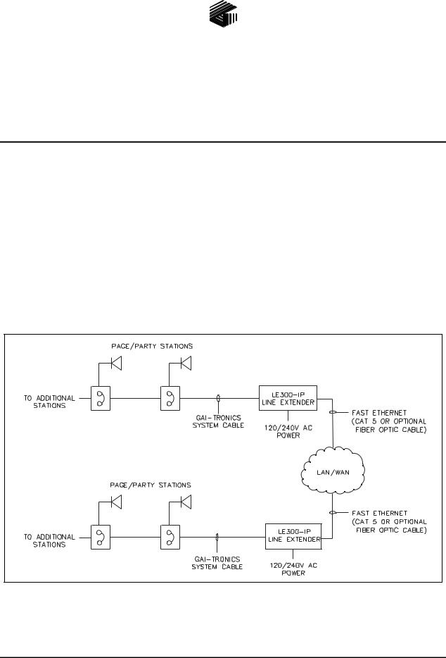
The GAI-Tronics Model LE300-IP Line Extenders are used in pairs to connect two Page/Party®, SmartSeries or ICS Page/Party® cable segments over an IP Network using Fast Ethernet or Gigabit Ethernet access. Refer to Figure 1 for a typical block diagram.
Figure 1. Typical System Block Diagram
GAI-Tronics Corporation 400 E. Wyomissing Ave. Mohnton, PA 19540 USA
610-777-1374 800-492-1212 Fax: 610-796-5954
VISIT WWW.GAI-TRONICS.COM FOR PRODUCT LITERATURE AND MANUALS
MODEL LE300-IP PAGE/PARTY® LINE EXTENDER |
Pub. 42004-488C |
PAGE 2 of 68 |
Model LE300-IP Line Extender and Sub-Component Details
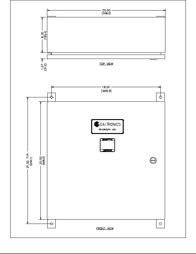
Refer to Figure 2 below for dimensional information and the sub-component layout of the Model LE300IP Line Extender.
Figure 2. Model LE300-IP Line Extender Outline
e:\standard ioms - current release\42004 instr. manuals\42004-488c.doc
09/14
MODEL LE300-IP PAGE/PARTY® LINE EXTENDER |
|
|
|
|
Pub. 42004-488C |
|||||||||||||||||||||||||||||||||||||||||||||||||||||||||||||||||||||||||||||||||||||||||||||||||||||||||||||||||||||||||||||||||||||||||||||||||||||||||||||||||||||||||||||||||||||||||||||||||||||||||
|
|
|
|
|
|
|
|
|
|
|
|
|
|
|
PAGE 3 of 68 |
|||||||||||||||||||||||||||||||||||||||||||||||||||||||||||||||||||||||||||||||||||||||||||||||||||||||||||||||||||||||||||||||||||||||||||||||||||||||||||||||||||||||||||||||||||||||||||||||
Model LE300-IPInternalView |
|
|
|
|
|
|
|
|
|
|
|
|
|
|
|
|
|
|
|
|
|
|
|
|
|
|
|
|
|
|
|
|
|
|
|
|
||||||||||||||||||||||||||||||||||||||||||||||||||||||||||||||||||||||||||||||||||||||||||||||||||||||||||||||||||||||||||||||||||||||||||||||||||||||||||||||||||||||||||
|
|
|
|
|
|
|
|
|
|
|
|
|
|
|
|
|
|
|
|
|
|
|
|
|
|
|
|
|
|
|
|
|
|
|
|
|
|
|
|
|
|
|
|
|
|
|
|
|
|
|
|
|
|
|
|
|
|
|
|
|
|
|
|
|
|
|
|
|
|
|
|
|
|
|
|
|
|
|
|
|
|
|
|
|
|
|
|
|
|
|
|
|
|
|
|
|
|
|
|
|
|
|
|
|
|
|
|
|
|
|
|
|
|
|
|
|
|
|
|
|
|
|
|
|
|
|
|
|
|
|
|
|
|
|
|
|
|
|
|
|
|
|
|
|
|
|
|
|
|
|
|
|
|
|
|
|
|
|
|
|
|
|
|
|
|
|
|
|
|
|
|
|
|
|
|
|
|
|
|
|
|
|
|
|
|
|
|
|
|
|
|
|
|
|
|
|
|
|
|
|
|
|
|
|
|
|
|
|
|
|
|
|
|
|
|
|
|
|
|
|
|
|
|
|
|
|
|
|
|
|
|
|
|
|
|
|
|
|
|
|
|
|
|
|
|
|
|
|
|
|
|
|
|
|
|
|
|
|
|
|
|
|
|
|
|
|
|
|
|
|
|
|
|
|
|
|
|
|
|
|
|
|
|
|
|
|
|
|
|
|
|
|
|
|
|
|
|
|
|
|
|
|
|
|
|
|
|
|
|
|
|
|
|
|
|
|
|
|
|
|
|
|
|
|
|
|
|
|
|
|
|
|
|
|
|
|
|
|
|
|
|
|
|
|
|
|
|
|
|
|
|
|
|
|
|
|
|
|
|
|
|
|
|
|
|
|
|
|
|
|
|
|
|
|
|
|
|
|
|
|
|
|
|
|
|
|
|
|
|
|
|
|
|
|
|
|
|
|
|
|
|
|
|
|
|
|
|
|
|
|
|
|
|
|
|
|
|
|
|
|
|
|
|
|
|
|
|
|
|
|
|
|
|
|
|
|
|
|
|
|
|
|
|
|
|
|
|
|
|
|
|
|
|
|
|
|
|
|
|
|
|
|
|
|
|
|
|
|
|
|
|
|
|
|
|
|
|
|
|
|
|
|
|
|
|
|
|
|
|
|
|
|
|
|
|
|
|
|
|
|
|
|
|
|
|
|
|
|
|
|
|
|
|
|
|
|
|
|
|
|
|
|
|
|
|
|
|
|
|
|
|
|
|
|
|
|
|
|
|
|
|
|
|
|
|
|
|
|
|
|
|
|
|
|
|
|
|
|
|
|
|
|
|
|
|
|
|
|
|
|
|
|
|
|
|
|
|
|
|
|
|
|
|
|
|
|
|
|
|
|
|
|
|
|
|
|
|
|
|
|
|
|
|
|
|
|
|
|
|
|
|
|
|
|
|
|
|
|
|
|
|
|
|
|
|
|
|
|
|
|
|
|
|
|
|
|
|
|
|
|
|
|
|
|
|
|
|
|
|
|
|
|
|
|
|
|
|
|
|
|
|
|
|
|
|
|
|
|
|
|
|
|
|
|
|
|
|
|
|
|
|
|
|
|
|
|
|
|
|
|
|
|
|
|
|
|
|
|
|
|
|
|
|
|
|
|
|
|
|
|
|
|
|
|
|
|
|
|
|
|
|
|
|
|
|
|
|
|
|
|
|
|
|
|
|
|
|
|
|
|
|
|
|
|
|
|
|
|
|
|
|
|
|
|
|
|
|
|
|
|
|
|
|
|
|
|
|
|
|
|
|
|
|
|
|
|
|
|
|
|
|
|
|
|
|
|
|
|
|
|
|
|
|
|
|
|
|
|
|
|
|
|
|
|
|
|
|
|
|
|
|
|
|
|
|
|
|
|
|
|
|
|
|
|
|
|
|
|
|
|
|
|
|
|
|
|
|
|
|
|
|
|
|
|
|
|
|
|
|
|
|
|
|
|
|
|
|
|
|
|
|
|
|
|
|
|
|
|
|
|
|
|
|
|
|
|
|
|
|
|
|
|
|
|
|
|
|
|
|
|
|
|
|
|
|
|
|
|
|
|
|
|
|
|
|
|
|
|
|
|
|
|
|
|
|
|
|
|
|
|
|
|
|
|
|
|
|
|
|
|
|
|
|
|
|
|
|
|
|
|
|
|
|
|
|
|
|
|
|
|
|
|
|
|
|
|
|
|
|
|
|
|
|
|
|
|
|
|
|
|
|
|
|
|
|
|
|
|
|
|
|
|
|
|
|
|
|
|
|
|
|
|
|
|
|
|
|
|
|
|
|
|
|
|
|
|
|
|
|
|
|
|
|
|
|
|
|
|
|
|
|
|
|
|
|
|
|
|
|
|
|
|
|
|
|
|
|
|
|
|
|
|
|
|
|
|
|
|
|
|
|
|
|
|
|
|
|
|
|
|
|
|
|
|
|
|
|
|
|
|
|
|
|
|
|
|
|
|
|
|
|
|
|
|
|
|
|
|
|
|
|
|
|
|
|
|
|
|
|
|
|
|
|
|
|
|
|
|
|
|
|
|
|
|
|
|
|
|
|
|
|
|
|
|
|
|
|
|
|
|
|
|
|
|
|
|
|
|
|
|
|
|
|
|
|
|
|
|
|
|
|
|
|
|
|
|
|
|
|
|
|
|
|
|
|
|
|
|
|
|
|
|
|
|
|
|
|
|
|
|
|
|
|
|
|
|
|
|
|
|
|
|
|
|
|
|
|
|
|
|
|
|
|
|
|
|
|
|
|
|
|
|
|
|
|
|
|
|
|
|
|
|
|
|
|
|
|
|
|
|
|
|
|
|
|
|
|
|
|
|
|
|
|
|
|
|
|
|
|
|
|
|
|
|
|
|
|
|
|
|
|
|
|
|
|
|
|
|
|
|
|
|
|
|
|
|
|
|
|
|
|
|
|
|
|
|
|
|
|
|
|
|
|
|
|
|
|
|
|
|
|
|
|
|
|
|
|
|
|
|
|
|
|
|
|
|
|
|
|
|
|
|
|
|
|
|
|
|
|
|
|
|
|
|
|
|
|
|
|
|
|
|
|
|
|
|
|
|
|
|
|
|
|
|
|
|
|
|
|
|
|
|
|
|
|
|
|
|
|
|
|
|
|
|
|
|
|
|
|
|
|
|
|
|
|
|
|
|
|
|
|
|
|
|
|
|
|
|
|
|
|
|
|
|
|
|
|
|
|
|
|
|
|
|
|
|
|
|
|
|
|
|
|
|
|
|
|
|
|
|
|
|
|
|
|
|
|
|
|
|
|
|
|
|
|
|
|
|
|
|
|
|
|
|
|
|
|
|
|
|
|
|
|
|
|
|
|
|
|
|
|
|
|
|
|
|
|
|
|
|
|
|
|
|
|
|
|
|
|
|
|
|
|
|
|
|
|
|
|
|
|
|
|
|
|
|
|
|
|
|
|
|
|
|
|
|
|
|
|
|
|
|
|
|
|
|
|
|
|
|
|
|
|
|
|
|
|
|
|
|
|
|
|
|
|
|
|
|
|
|
|
|
|
|
|
|
|
|
|
|
|
|
|
|
|
|
|
|
|
|
|
|
|
|
|
|
|
|
|
|
|
|
|
|
|
|
|
|
|
|
|
|
|
|
|
|
|
|
|
|
|
|
|
|
|
|
|
|
|
|
|
|
|
|
|
|
|
|
|
|
|
|
|
|
|
|
|
|
|
|
|
|
|
|
|
|
|
|
|
|
|
|
|
|
|
|
|
|
|
|
|
|
|
|
|
|
|
|
|
|
|
|
|
|
|
|
|
|
|
|
|
|
|
|
|
|
|
|
|
|
|
|
|
|
|
|
|
|
|
|
|
|
|
|
|
|
|
|
|
|
|
|
|
|
|
|
|
|
|
|
|
|
|
|
|
|
|
|
|
|
|
|
|
|
|
|
|
|
|
|
|
|
|
|
|
|
|
|
|
|
|
|
|
|
|
|
|
|
|
|
|
|
|
|
|
|
|
|
|
|
|
|
|
|
|
|
|
|
|
|
|
|
|
|
|
|
|
|
|
|
|
|
|
|
|
|
|
|
|
|
|
|
|
|
|
|
|
|
|
|
|
|
|
|
|
|
|
|
|
|
|
|
|
|
|
|
|
|
|
|
|
|
|
|
|
|
|
|
|
|
|
|
|
|
|
|
|
|
|
|
|
|
|
|
|
|
|
|
|
|
|
|
|
|
|
|
|
|
|
|
|
|
|
|
|
|
|
|
|
|
|
|
|
|
|
|
|
|
|
|
|
|
|
|
|
|
|
|
|
|
|
|
|
|
|
|
|
|
|
|
|
|
|
|
|
|
|
|
|
|
|
|
|
|
|
|
|
|
|
|
|
|
|
|
|
|
|
|
|
|
|
|
|
|
|
|
|
|
|
|
|
|
|
|
|
|
|
|
|
|
|
|
|
|
|
|
|
|
|
|
|
|
|
|
|
|
|
|
|
|
|
|
|
|
|
|
|
|
|
|
|
|
|
|
|
|
|
|
|
|
|
|
|
|
|
|
|
|
|
|
|
|
|
|
|
|
|
|
|
|
|
|
|
|
|
|
|
|
|
|
|
|
|
|
|
|
|
|
|
|
|
|
|
|
|
|
|
|
|
|
|
|
|
|
|
|
|
|
|
|
|
|
|
|
|
|
|
|
|
|
|
|
|
|
|
|
|
|
|
|
|
|
|
|
|
|
|
|
|
|
|
|
|
|
|
|
|
|
|
|
|
|
|
|
|
|
|
|
|
|
|
|
|
|
|
|
|
|
|
|
|
|
|
|
|
|
|
|
|
|
|
|
|
|
|
|
|
|
|
|
|
|
|
|
|
|
|
|
|
|
|
|
|
|
|
|
|
|
|
|
|
|
|
|
|
|
|
|
|
|
|
|
|
|
|
|
|
|
|
|
|
|
|
|
|
|
|
|
|
|
|
|
|
|
|
|
|
|
|
|
|
|
|
|
|
|
|
|
|
|
|
|
|
|
|
|
|
|
|
|
|
|
|
|
|
|
|
|
|
|
|
|
|
|
|
|
|
|
|
|
|
|
|
|
|
|
|
|
|
|
|
|
|
|
|
|
|
|
|
|
|
|
|
|
|
|
|
|
|
|
|
|
|
|
|
|
|
|
|
|
|
|
|
|
|
|
|
|
|
|
|
|
|
|
|
|
|
|
|
|
|
|
|
|
|
|
|
|
|
|
|
|
|
|
|
|
|
|
|
|
|
|
|
|
|
|
|
|
|
|
|
|
|
|
|
|
|
|
|
|
|
|
|
|
|
|
|
|
|
|
|
|
|
|
|
|
|
|
|
|
|
|
|
|
|
|
|
|
|
|
|
|
|
|
|
|
|
|
|
|
|
|
|
|
|
|
|
|
|
|
|
|
|
|
|
|
|
|
|
|
|
|
|
|
|
|
|
|
|
|
|
|
|
|
|
|
|
|
|
|
|
|
|
|
|
|
|
|
|
|
|
|
|
|
|
|
|
|
|
|
|
|
|
|
|
|
|
|
|
|
|
|
|
|
|
|
|
|
|
|
|
|
|
|
|
|
|
|
|
|
|
|
|
|
|
|
|
|
|
|
|
|
|
|
|
|
|
|
|
|
|
|
|
|
|
|
|
|
|
|
|
|
|
|
|
|
|
|
|
|
|
|
|
|
|
|
|
|
|
|
|
|
|
|
|
|
|
|
|
|
|
|
|
|
|
|
|
|
|
|
|
|
|
|
|
|
|
|
|
|
|
|
|
|
|
|
|
|
|
|
|
|
|
|
|
|
|
|
|
|
|
|
|
|
|
|
|
|
|
|
|
|
|
|
|
|
|
|
|
|
|
|
|
|
|
|
|
|
|
|
|
|
|
|
|
|
|
|
|
|
|
|
|
|
|
|
|
|
|
|
|
|
|
|
|
|
|
|
|
|
|
|
|
|
|
|
|
|
|
|
|
|
|
|
|
|
|
|
|
|
|
|
|
|
|
|
|
|
|
|
|
|
|
|
|
|
|
|
|
|
|
|
|
|
|
|
|
|
|
|
|
|
|
|
|
|
|
|
|
|
|
|
|
|
|
|
|
|
|
|
|
|
|
|
|
|
|
|
|
|
|
|
|
|
|
|
|
|
|
|
|
|
|
|
|
|
|
|
|
|
|
|
|
|
|
|
|
|
|
|
|
|
|
|
|
|
|
|
|
|
|
|
|
|
|
|
|
|
|
|
|
|
|
|
|
|
|
|
|
|
|
|
|
|
|
|
|
|
|
|
|
|
|
|
|
|
|
|
|
|
|
|
|
|
|
|
|
|
|
|
|
|
|
|
|
|
|
|
|
|
|
|
|
|
|
|
|
|
|
|
|
|
|
|
|
|
|
|
|
|
|
|
|
|
|
|
|
|
|
|
|
|
|
|
|
|
|
|
|
|
|
|
|
|
|
|
|
|
|
|
|
|
|
|
|
|
|
|
|
|
|
|
|
|
|
|
|
|
|
|
|
|
|
|
|
|
|
|
|
|
|
|
|
|
|
|
|
|
|
|
|
|
|
|
|
|
|
|
|
|
|
|
|
|
|
|
|
|
|
|
|
|
|
|
|
|
|
|
|
|
|
|
|
|
|
|
|
|
|
|
|
|
|
|
|
|
|
|
|
|
|
|
|
|
|
|
|
|
|
|
|
|
|
|
|
|
|
|
|
|
|
|
|
|
|
|
|
|
|
|
|
|
|
|
|
|
|
|
|
|
|
|
|
|
|
|
|
|
|
|
|
|
|
|
|
|
|
|
|
|
|
|
|
|
|
|
|
|
|
|
|
|
|
|
|
|
|
|
|
|
|
|
|
|
|
|
|
|
|
|
|
|
|
|
|
|
|
|
|
|
|
|
|
|
|
|
|
|
|
|
|
|
|
|
|
|
|
|
|
|
|
|
|
|
|
|
|
|
|
|
|
|
|
|
|
|
|
|
|
|
|
|
|
|
|
|
|
|
|
|
|
|
|
|
|
|
|
|
|
|
|
|
|
|
|
|
|
|
|
|
|
|
|
|
|
|
|
|
|
|
|
|
|
|
|
|
|
|
|
|
|
|
|
|
|
|
|
|
|
|
|
|
|
|
|
|
|
|
|
|
|
|
|
|
|
|
|
|
|
|
|
|
|
|
|
|
|
|
|
|
|
|
|
|
|
|
|
|
|
|
|
|
|
|
|
|
|
|
|
|
|
|
|
|
|
|
|
|
|
|
|
|
|
|
|
|
|
|
|
|
|
|
|
|
|
|
|
|
|
|
|
|
|
|
|
|
|
|
|
|
|
|
|
|
|
|
|
|
|
|
|
|
|
|
|
|
|
|
|
|
|
|
|
|
|
|
|
|
|
|
|
|
|
|
|
|
|
|
|
|
|
|
|
|
|
|
|
|
|
|
|
|
|
|
|
|
|
|
|
|
|
|
|
|
|
|
|
|
|
|
|
|
|
|
|
|
|
|
|
|
|
|
|
|
|
|
|
|
|
|
|
|
|
|
|
|
|
|
|
|
|
|
|
|
|
|
|
|
|
|
|
|
|
|
|
|
|
|
|
|
|
|
|
|
|
|
|
|
|
|
|
|
|
|
|
|
|
|
|
|
|
|
|
|
|
|
|
|
|
|
|
|
|
|
|
|
|
|
|
|
|
|
|
|
|
|
|
|
|
|
|
|
|
|
|
|
|
|
|
|
|
|
|
|
|
|
|
|
|
|
|
|
|
|
|
|
|
|
|
|
|
|
|
|
|
|
|
|
|
|
|
|
|
|
|
|
|
|
|
|
|
|
|
|
|
|
|
|
|
|
|
|
|
|
|
|
|
|
|
|
|
|
|
|
|
|
|
|
|
|
|
|
|
|
|
|
|
|
|
|
|
|
|
|
|
|
|
|
|
|
|
|
|
|
|
|
|
|
|
|
|
|
|
|
|
|
|
|
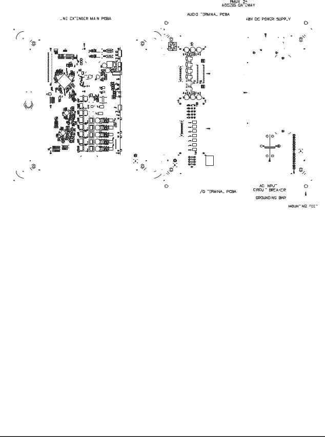
Figure 3. Interior View of Components - Model LE300-IP
e:\standard ioms - current release\42004 instr. manuals\42004-488c.doc
09/14
MODEL LE300-IP PAGE/PARTY® LINE EXTENDER |
Pub. 42004-488C |
PAGE 4 of 68 |
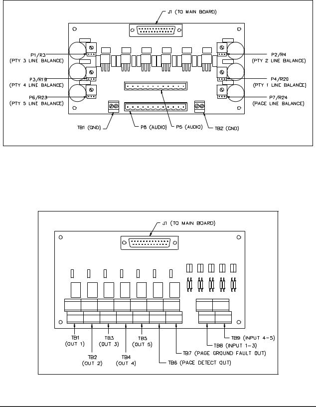
AudioTerminationConnectionModule
The page line and party line 1–5 conductors of the Page/Party® system cable connect to the Audio Termination Connection Module. This module also can provide the 33-ohm line balance resistance needed for the audio lines. Audio line functions are described later in this manual.
Figure 4. Audio Termination Connection Module
Input/Output (I/O)TerminationConnectionModule
The I/O Termination Connection Module connects the control wiring needed to send contact closures across the line extenders. I/O features and functions are described later in this manual.
Figure 5. Input/ Output (I/O) Connection Module
e:\standard ioms - current release\42004 instr. manuals\42004-488c.doc
09/14

MODEL LE300-IP PAGE/PARTY® LINE EXTENDER |
Pub. 42004-488C |
PAGE 5 of 68 |
MainPCBA
The Main PCBA contains all the central processing and line driver circuitry for the Model LE300-IP Line Extender. The board contains numerous connectors, switches and jumpers for setting the line extender operating parameters. Figure 6 below identifies the various components on the Main PCBA. Features and functions of each are described later in this manual.
Figure 6. Main PCBA
e:\standard ioms - current release\42004 instr. manuals\42004-488c.doc
09/14

MODEL LE300-IP PAGE/PARTY® LINE EXTENDER |
Pub. 42004-488C |
PAGE 6 of 68 |
Features and Functions
The Model LE300-IP Page/Party® Line Extender provides the following features between Page/Party® system cables.
Page Line Audio Transmission
A pair of Model LE300-IP Line Extenders provides page line audio transmission between two Page/Party® system cables. This transmission is half-duplex operation.
When the line extender detects a peak audio level equal or above a Peak Voltage Level Detection Threshold, it immediately switches audio “on” in that direction for the Transmission Direction Hold Time. Audio from the other direction is muted and ignored during that time. Audio is not switched “off” until it is continuously below the Peak Voltage Level Detection Threshold for the Transmission Direction Hold Time. The DIP switch SW2 positions 5–7, located on the Main PCBA, selects Peak Voltage Level Detection Threshold and Transmission Direction Hold Time. Refer to Figure 6 for the location of Switch SW2 on the Main PCBA and Table 1 and Table 2 below for setting options.
Table 1. Transmission Direction Hold Time Settings on Main PCBA
SW2-5 |
SW2-6 |
Transmission Direction Hold Time |
|
|
|
|
|
|
Open* |
Open * |
1280 milliseconds |
|
|
|
Closed |
Open |
640 milliseconds |
|
|
|
Open |
Closed |
160 milliseconds |
|
|
|
Closed |
Closed |
40 milliseconds |
|
|
|
NOTES: 1. Changes to this parameter take effect without cycling power. 2. *Indicates default position.
Table 2. Peak Voltage Level Detection Threshold on Main PCBA
SW2-7 |
Peak Voltage Level Detection Threshold |
|
|
|
|
Open* |
−12 dB relative to nominal |
|
|
Closed |
−24 dB relative to nominal |
|
|
NOTES: 1. Changes to this parameter take effect without cycling power. 2. *Indicates default position.
e:\standard ioms - current release\42004 instr. manuals\42004-488c.doc
09/14

MODEL LE300-IP PAGE/PARTY® LINE EXTENDER |
Pub. 42004-488C |
PAGE 7 of 68 |
Page Line Audio Monitoring Output
The Model LE300-IP Line Extender provides a balanced 600-ohm audio output for monitoring audio on both the local and remote page lines. The LE300-IP mixes the local and remote page line audio and routes it to the 600-ohm audio output terminals. This audio can be sent to any external audio device (recorder, radio transmitter, amplifier, etc.) with an input impedance equal to or greater than 600 ohms. The audio output gain is adjustable using DIP switch SW3 positions 5–8 on the Main PCBA. Refer to Figure 6 for the location of Switch SW3 on the Main PCBA and the tables below for setting options.
Table 3. Page Line Monitor Output Gain Setting on Main PCBA
|
|
|
|
Monitor Output |
SW3-5 |
SW3-6 |
SW3-7 |
SW3-8 |
Gain |
|
|
|
|
|
|
|
|
|
|
Open* |
Open* |
Open* |
Open* |
0 dB |
|
|
|
|
|
Closed |
Open |
Open |
Open |
−30 dB |
|
|
|
|
|
Open |
Closed |
Open |
Open |
−27 dB |
|
|
|
|
|
Closed |
Closed |
Open |
Open |
−24 dB |
|
|
|
|
|
Open |
Open |
Closed |
Open |
−21 dB |
|
|
|
|
|
Closed |
Open |
Closed |
Open |
−18 dB |
|
|
|
|
|
Open |
Closed |
Closed |
Open |
−15 dB |
|
|
|
|
|
Closed |
Closed |
Closed |
Open |
−12 dB |
|
|
|
|
|
Open |
Open |
Open |
Closed |
−9 dB |
|
|
|
|
|
Closed |
Open |
Open |
Closed |
−6 dB |
|
|
|
|
|
Open |
Closed |
Open |
Closed |
−3 dB |
|
|
|
|
|
Closed |
Closed |
Open |
Closed |
0 dB |
|
|
|
|
|
Open |
Open |
Closed |
Closed |
+3 dB |
|
|
|
|
|
Closed |
Open |
Closed |
Closed |
+6 dB |
|
|
|
|
|
Open |
Closed |
Closed |
Closed |
+9 dB |
|
|
|
|
|
Closed |
Closed |
Closed |
Closed |
+12 dB |
|
|
|
|
|
NOTES: 1. Changes to this parameter take effect without cycling power. 2. *Indicates default position.
e:\standard ioms - current release\42004 instr. manuals\42004-488c.doc
09/14
MODEL LE300-IP PAGE/PARTY® LINE EXTENDER |
Pub. 42004-488C |
PAGE 8 of 68 |
Page Line Audio Detect Output Contact
The Model LE300-IP Line Extender provides a contact closure output that activates whenever audio is detected on the page line. The contact can be set to close when audio is detected at the local page line, the remote page line, or both. Typically this contact is used in conjunction with the Page Line Audio Monitoring Output to provide a control contact to external devices or systems when page line audio is present. The contact remains active for 1 second after the audio is no longer detected. DIP switch SW5 positions 6 and 7 enables or disables the output contact. Refer to Figure 6 for the location of switch SW5 on the Main PCBA and the tables below for setting options.
Table 4. Page Line Audio Detect Contact Main PCBA
SW5-6 |
SW5-7 |
Audio Detect Contact Operation |
|
|
|
|
|
|
Closed |
Closed |
Disabled |
|
|
|
Open |
Closed |
Local page line audio activates the contact |
|
|
|
Closed |
Open |
Remote page line audio activates the contact |
|
|
|
Open* |
Open* |
Both Local and Remote page line audio activates the contact |
|
|
|
NOTES: 1. Changes to this parameter take effect without cycling power. 2. *Indicates default position.
Page Line FSK Data Transmission (SmartSeries Systems)
A pair of Model LE300-IP Line Extenders re-generates the FSK data transmission between two SmartSeries Page/Party® system cables. FSK data transmission occurs on the page line allowing SmartSeries Page/Party® stations to communicate with the ADVANCE system control cabinet. For proper operation, both line extenders must have this feature enabled by setting DIP switch SW5 position 1. Refer to Figure 6 for the location of switch SW5 on the Main PCBA and Table 5 below for setting options.
|
Table 5. Page Line FSK Transmission on Main PCBA |
|
|
SW5-1 |
Page Line FSK Transmission |
|
|
|
|
Open* |
FSK data is disabled. |
|
|
Closed |
FSK data is enabled. |
|
|
NOTES: 1. Changes to this parameter take effect without cycling power. 2. *Indicates default position.
NOTE: FSK operation and VLC operation (described below) cannot be enabled at the same time. FSK operation is only used with SmartSeries systems.
VLC operation is only used within NON-SmartSeries systems. If both 50 kHz VLC and FSK are enabled at the same time, neither feature will function correctly.
e:\standard ioms - current release\42004 instr. manuals\42004-488c.doc
09/14

MODEL LE300-IP PAGE/PARTY® LINE EXTENDER |
Pub. 42004-488C |
PAGE 9 of 68 |
Page Line 50 kHz VLC Transmission
A pair of Model LE300-IP Line Extenders re-generates the 50 kHz VLC control signal between two Page/Party® system cables. The 50 kHz VLC (Volume Level Control) signaling occurs on the page line and is typically used to alter the speaker volume of Page/Party® stations equipped VLC receivers. VLC signals may also be used for other on/off control functions on some Page/Party® systems. For proper operation, both line extenders must have this feature enabled by setting DIP switch SW5 position 2. Refer to Figure 6 for the location of switch SW5 on the Main PCBA and Table 6 below for setting options.
Table 6. Page Line 50 kHz VLC Transmission Setting on Main PCBA
SW5-2 Page Line 50 kHz VLC Transmission
Open* |
50 kHz VLC is disabled. |
|
|
Closed |
50 kHz VLC is enabled. |
|
|
NOTES: 1. Changes to this parameter take effect without cycling power. 2. *Indicates default position.
NOTE: FSK operation and VLC operation (described above) cannot be enabled at the same time. FSK operation is only used with SmartSeries systems.
VLC operation is only used within NON-SmartSeries systems. If both 50 kHz VLC and FSK are enabled at the same time, neither feature will function correctly.
Page Line Ground Fault Detection
The Model LE300-IP Line Extenders provide page line ground fault detection on the local Page/Party® system cable. If multiple line extenders are connected to the same Page/Party® system cable segment, only one page line ground fault detector may be enabled. A shorting clip setting at header P5 on the Main PCBA enables the page line ground fault detection. Refer to Figure 6 for the location of header P5 on the Main PCBA and Table 7 below for setting options:
Table 7. Page Line Ground Fault Detection Setting on Main PCBA
P5 Shorting Clip |
Page Line Ground Fault Detection |
|
|
|
|
Pins 1–2* |
Page line ground fault detection is disabled. |
|
|
Pins 2–3 |
Page line ground fault detection is enabled. |
|
|
Removed |
Page line ground fault detection is disabled. |
|
|
NOTES:
1.If connecting an LE300-IP Line Extender to the same system cable segment as an ADVANCE Page/Party® Interface (PPI) card, disable the LE300-IP page line ground fault detector. The PPI card contains the ground fault detector. If both ground fault circuits are enabled simultaneously, intermittent SmartSeries FSK data errors will occur between the PPI card and SmartSeries stations.
2.Changes to this parameter take effect without cycling power.
3.*Indicates default position.
e:\standard ioms - current release\42004 instr. manuals\42004-488c.doc
09/14

MODEL LE300-IP PAGE/PARTY® LINE EXTENDER |
Pub. 42004-488C |
PAGE 10 of 68 |
Page Line Ground Fault Re-generation
When a ground fault is detected at a remote LE300-IP Line Extender, the ground fault can be duplicated on the local Page/Party® system cable. DIP switch SW5 position 3 enables regeneration of the ground fault. Refer to Figure 6 for the location of switch SW5 on the Main PCBA and Table 8 below for setting options.
|
Table 8. Page Line Ground Fault Regeneration Setting on Main PCBA |
|
|
SW5-3 |
Page Line Ground Fault Regeneration |
|
|
|
|
Open* |
Disabled - Page line ground faults detected on the remote system cable are NOT |
|
regenerated on the local system cable. |
|
|
Closed |
Enabled - Page line ground faults detected on the remote system cable are regenerated on |
|
the local system cable. |
|
|
NOTES:
1.The ground fault regeneration feature is used in SmartSeries systems to allow a ground fault on the remote cable segment to be detected by the system control cabinet. Disable this feature if the line extender is not installed in this type system.
2.Changes to this parameter take effect without cycling power.
3.*Indicates default position.
Page Line Ground Fault Output Contact
The Model LE300-IP provides a relay contact that activates whenever a ground fault is detected on the local page line, remote page line or both the page lines. The ground fault detection feature (described above) must be enabled. The contact output can be used to activate an external device or system that annunciates the fault condition. The DIP switch SW5 positions 4 and 5 configure which page line ground faults activate this contact. Refer to Figure 6 for the location of switch SW5 on the Main PCBA and Table 9 below for setting options.
Table 9. Page Line Ground Fault Contact Setting on Main PCBA
SW5-4 |
SW5-5 |
Page Line Ground Fault Contact |
|
|
|
|
|
|
Closed |
Closed |
Disabled |
|
|
|
Closed |
Open |
Remote page line ground fault activates the contact. |
|
|
|
Open |
Closed |
Local page line ground fault activates the contact. |
|
|
|
Open* |
Open* |
Both Local and Remote page line ground faults activate the contact. |
|
|
|
NOTES: 1. Changes to this parameter take effect without cycling power. 2. *Indicates default position.
e:\standard ioms - current release\42004 instr. manuals\42004-488c.doc
09/14

MODEL LE300-IP PAGE/PARTY® LINE EXTENDER |
Pub. 42004-488C |
PAGE 11 of 68 |
Party Line Audio Transmission
A pair of Model LE300-IP Line Extenders provides full duplex party line audio between two Page/Party® system cables, for party lines 1 through 5. During on-hook conditions of the party lines (meaning no handset stations are in use), the LE300-IP will mute the local party line analog circuits.
If it is necessary to have party line audio enabled even when no stations are off-hook, DIP switch SW6-3 may be closed to disable this muting feature. This switch affects the on-hook muting function of all five party lines simultaneously.
Refer to Figure 6 for the location of switch SW6 on the Main PCBA and Table 10 below for setting options.
|
Table 10. Party Line On-Hook Muting Setting on Main PCBA |
|
|
SW6-3 |
Party Line On-Hook Muting |
|
|
|
|
Open* |
Enabled – local party lines are muted when no handset stations are in use. |
|
|
Closed |
Disabled – party line audio is never muted. |
|
|
NOTES: 1. Changes to this parameter take effect without cycling power. 2. *Indicates default position.
e:\standard ioms - current release\42004 instr. manuals\42004-488c.doc
09/14

MODEL LE300-IP PAGE/PARTY® LINE EXTENDER |
Pub. 42004-488C |
PAGE 12 of 68 |
Party Line Off-Hook Detection
The Model LE300-IP Line Extenders provide off-hook detection on the local Page/Party® system cable for party lines 1 through 5. An off-hook condition means a handset station is in use. If multiple line extenders are connected to the same Page/Party® system cable segment, only one off-hook detector can be enabled.
If connecting an LE300-IP to the same system cable segment as an ADVANCE Page/Party® Interface (PPI) card, disable the LE300-IP off-hook detection for party lines 1 and 2. The PPI card contains offhook detection for party lines 1 and 2.
Several shorting clips (P6–P15) are used to enable the off-hook detection feature on party line 1 through 5. Two shorting clips are associated with each party line and must be set to the same position for proper operation. The party lines 1 through 5 are configured independently. Refer to Figure 6 for the location of P6–P15 on the Main PCBA and Table 11 below for setting options.
Table 11. Party Line Off-Hook Detection Setting on Main PCBA
Party Line |
Headers |
Shorting Clip |
Off-Hook Detection |
|
|
|
|
|
|
|
|
|
|
|
|
|
|
Pins 1–2* |
Disabled |
|
|
|
|
|
Party Line 1 |
P15, |
P14 |
Pins 2–3 |
Enabled |
|
|
|
|
|
|
|
|
Removed |
Disabled |
|
|
|
|
|
|
|
|
Pins 1–2* |
Disabled |
|
|
|
|
|
Party Line 2 |
P13, |
P12 |
Pins 2–3 |
Enabled |
|
|
|
|
|
|
|
|
Removed |
Disabled |
|
|
|
|
|
|
|
|
Pins 1–2* |
Disabled |
|
|
|
|
|
Party Line 3 |
P11, |
P10 |
Pins 2–3 |
Enabled |
|
|
|
|
|
|
|
|
Removed |
Disabled |
|
|
|
|
|
|
|
|
Pins 1–2* |
Disabled |
|
|
|
|
|
Party Line 4 |
P9, |
P8 |
Pins 2–3 |
Enabled |
|
|
|
|
|
|
|
|
Removed |
Disabled |
|
|
|
|
|
|
|
|
Pins 1–2* |
Disabled |
|
|
|
|
|
Party Line 5 |
P7, |
P6 |
Pins 2–3 |
Enabled |
|
|
|
|
|
|
|
|
Removed |
Disabled |
|
|
|
|
|
NOTES:
1.Changes to this parameter take effect without cycling power.
2.*Indicates default position.
e:\standard ioms - current release\42004 instr. manuals\42004-488c.doc
09/14

MODEL LE300-IP PAGE/PARTY® LINE EXTENDER |
Pub. 42004-488C |
PAGE 13 of 68 |
Party Line Off-Hook Regeneration
When an off-hook handset station is detected, the LE300-IP can transmit the off-hook condition to remote line extenders so that it is duplicated on the remote Page/Party® system cable. Typically this feature is used in systems that contain a telephone interface device so that the caller is transferred to the party line when a handset station answers the call. DIP switch SW6 position 2 is used to enable this feature. This switch affects the off-hook regeneration function of all five party lines. Refer to Figure 6 for the location SW6 on the Main PCBA and Table 12 below for setting options.
|
Table 12. Off-Hook Regeneration on Main PCBA |
|
|
SW6-2 |
Off-Hook Regeneration Setting |
|
|
|
|
Open* |
Enabled – an off hook condition on the local party line is regenerated at the |
|
remote line extender. |
|
|
Closed |
Disabled |
|
|
NOTES: 1. Changes to this parameter take effect without cycling power. 2. *Indicates default position.
Audio Line Muting
In some line extender configurations using the LVDS data link, the Page/Party® system cable is not connected to the line extender. In this case, all audio lines (page and party lines 1 through 5) should be muted since they are not physically connected. DIP switch SW6 position 4 on the Main PCBA enables this feature. If this feature is enabled, it is unnecessary to disconnect the audio lines using the audio line relays (mentioned above). Refer to Figure 6 for the location of SW6 on the Main PCBA and Table 13 below for setting options.
|
Table 13. Audio Line Mute Setting on Main PCBA |
|
|
SW6-4 |
Mute Analog Lines Setting |
|
|
|
|
Open* |
Disabled - Party lines 1–5 and page line are operational. |
|
|
Closed |
Enabled - Party lines 1–5 and page line are muted. |
|
|
NOTES: 1. Changes to this parameter take effect without cycling power. 2. *Indicates default position.
e:\standard ioms - current release\42004 instr. manuals\42004-488c.doc
09/14

MODEL LE300-IP PAGE/PARTY® LINE EXTENDER |
Pub. 42004-488C |
PAGE 14 of 68 |
Audio Line Connection Relays
The Model LE300-IP has relays that disconnect the page, party lines 1 through 5 and the page monitoring audio output connections from the Main PCBA. The disconnect feature is used for special applications such as connection of a single party line system, or other scenarios in which a particular audio line is not physically connected to the line extender. DIP switch SW4 is used to control the audio line disconnect feature. Refer to Figure 6 for the location of SW4 on the Main PCBA and Table 14 below for setting options.
Table 14. Audio Line Connection Relay Settings on Main PCBA
Audio Line |
Switch SW4 |
Setting |
Field Wiring |
|
|
|
|
|
|
|
|
|
|
|
Party Line 5 |
SW4-1 |
Open |
Disconnected |
|
|
|
|||
Closed* |
Connected |
|||
|
|
|||
|
|
|
|
|
Party Line 4 |
SW4-2 |
Open |
Disconnected |
|
|
|
|||
Closed* |
Connected |
|||
|
|
|||
|
|
|
|
|
Party Line 3 |
SW4-3 |
Open |
Disconnected |
|
|
|
|||
Closed* |
Connected |
|||
|
|
|||
|
|
|
|
|
Party Line 2 |
SW4-4 |
Open |
Disconnected |
|
|
|
|||
Closed* |
Connected |
|||
|
|
|||
|
|
|
|
|
Party Line 1 |
SW4-5 |
Open |
Disconnected |
|
|
|
|||
Closed* |
Connected |
|||
|
|
|||
|
|
|
|
|
Page Line |
SW4-6 |
Open |
Disconnected |
|
|
|
|||
Closed* |
Connected |
|||
|
|
|||
|
|
|
|
|
Page Monitor |
SW4-7 |
Open |
Disconnected |
|
|
|
|||
Closed* |
Connected |
|||
|
|
|||
|
|
|
|
|
N/A |
SW4-8 |
Open |
Not used. |
|
|
||||
Closed* |
||||
|
|
|
||
|
|
|
|
NOTES: 1. Changes to this parameter take effect without cycling power. 2. *Indicates default position.
e:\standard ioms - current release\42004 instr. manuals\42004-488c.doc
09/14

MODEL LE300-IP PAGE/PARTY® LINE EXTENDER |
Pub. 42004-488C |
PAGE 15 of 68 |
Page/Party®Line Balance
For proper system operation, the page line and party lines 1 through 5 must be terminated with a resistance of approximately 33 ohms. The Model LE300-IP provides potentiometers to set the line balance resistance on the page line and five party lines. The line balance resistors are located on the Audio Termination Connection Module next to the page and party line terminal blocks. The line balance resistors are adjustable or can be disabled using shorting clips P1–P7.
If connecting an LE300-IP Line Extender to the same system cable segment as an ADVANCE Page/Party® Interface (PPI) card, disable the line balance for party lines 1, 2, and the page line. The PPI card provides the line balance resistors for these audio lines. Refer to Figure 3 for the location of the Audio Termination Connection Module. Refer to Figure 4 for the location of the jumpers and potentiometers on the Audio Termination Connection Module and Table 15 below for setting details.
Table 15. Page/Party® Line Balance Settings on Audio Termination Connection Module
Audio Line |
Header |
Shorting Clip |
Line Balance |
Adjustment |
|
|
|
|
Potentiometer |
|
|
|
|
|
|
|
|
|
|
|
|
Pins 1–2* |
Disabled |
|
|
|
|
|
|
Party Line 5 |
P6 |
Pins 2–3 |
Enabled |
R23 |
|
|
|
|
|
|
|
Removed |
Disabled |
|
|
|
|
|
|
|
|
Pins 1–2* |
Disabled |
|
|
|
|
|
|
Party Line 4 |
P3 |
Pins 2–3 |
Enabled |
R19 |
|
|
|
|
|
|
|
Removed |
Disabled |
|
|
|
|
|
|
|
|
Pins 1–2* |
Disabled |
|
|
|
|
|
|
Party Line 3 |
P1 |
Pins 2–3 |
Enabled |
R3 |
|
|
|
|
|
|
|
Removed |
Disabled |
|
|
|
|
|
|
|
|
Pins 1–2* |
Disabled |
|
|
|
|
|
|
Party Line 2 |
P2 |
Pins 2–3 |
Enabled |
R4 |
|
|
|
|
|
|
|
Removed |
Disabled |
|
|
|
|
|
|
|
|
Pins 1–2* |
Disabled |
|
|
|
|
|
|
Party Line 1 |
P4 |
Pins 2–3 |
Enabled |
R20 |
|
|
|
|
|
|
|
Removed |
Disabled |
|
|
|
|
|
|
|
|
Pins 1–2* |
Disabled |
|
|
|
|
|
|
Page Line |
P7 |
Pins 2–3 |
Enabled |
R24 |
|
|
|
|
|
|
|
Removed |
Disabled |
|
|
|
|
|
|
NOTES: *Indicates default position.
e:\standard ioms - current release\42004 instr. manuals\42004-488c.doc
09/14

MODEL LE300-IP PAGE/PARTY® LINE EXTENDER |
Pub. 42004-488C |
PAGE 16 of 68 |
Contact Closure Inputs & Relay Outputs (I/O)
Five independent contact closures can be transmitted across a pair of line extenders, meaning that an active input contact on the local line extender results in the corresponding output relay contact energizing on the remote line extender. Contact closures are bi-directional between line extender pairs.
Example: Closing a switch contact across input #1 of the local line extender results in relay output #1 activating on the remote line extender and vice versa. When the input contact is removed the corresponding output relay de-activates. No switch or jumper setting is required on the Main PCBA for configuring the I/O feature.
NOTE: Any active output contacts will deactivate if the data link is broken between the line extenders.
Echo Cancellation
Line echo (also known as electric or hybrid echo) is created by the electrical circuitry connected to a twowire (full duplex) audio system. Echo is inherent in all full-duplex audio systems and is affected by the audio line length and line impedance mismatches. The presence of audible echoes results in undesirable audio quality. This kind of quality degradation is inherent in network equipment and end-user telephone devices.
To minimize echo, the Model LE300-IP performs an echo cancellation sequence on party lines 1 through 5. The echo cancellation process takes approximately 15 seconds and is performed automatically one minute after power is applied to the LE300-IP. This delay allows all power levels to stabilize prior to performing echo cancellation.
NOTE: Signal impulses are transmitted onto the party lines during the echo cancellation process. Handset station users on a party line will hear the signals in the handset receiver. For troubleshooting purposes, the 1-minute delay may be disabled by closing DIP switch SW6 position 1. Refer to Figure 6 for the location of SW6 on the Main PCBA and Table 16 below for setting details.
Table 16. Echo Cancellation Power-On Delay Setting on Main PCBA
SW6-1 |
Echo Cancellation Power-On Delay |
|
|
|
|
Open* |
1 minute |
|
|
Closed |
No delay |
|
|
NOTES: 1. Changes to this parameter take effect when cycling power. 2. *Indicates default position.
Manual InitiationofEchoCanceling
Echo cancellation can be manually initiated as described below.
Press and release push button PB1 on the Main PCBA three times. The push button must be pressed for at least 0.25 second and no more than 2 seconds each time. The timing requirement is meant to prevent accidental requests. If an error is made with the push-button timing, the sequence must be repeated from the beginning.
The LEDs on the Main PCBA will indicate the progress of the echo canceling sequence. One column of LEDs turns on after each push button and press release until the sequence is started. Once the sequence is started, those LEDs remain on, and a countdown timer is displayed on the remaining LEDs. The LEDs turn OFF after the echo cancellation training sequence is complete.
e:\standard ioms - current release\42004 instr. manuals\42004-488c.doc
09/14

MODEL LE300-IP PAGE/PARTY® LINE EXTENDER |
Pub. 42004-488C |
PAGE 17 of 68 |
Data Links between Line Extenders
The Model LE300-IP Line Extender is equipped with two different data link types for connecting to another line extender. The two data link types are a T1/E1 link via the IP network and a Low Voltage Differential Signaling (LVDS) link. The type of data link(s) used is determined by the system architecture. It is possible to use both types at the same time to achieve complex system architectures. The data link type, their intended use, and the applicable switch settings are described below.
T1/E1 over an Ethernet IP Network
This data link is used to connect two Model LE300-IP Line Extenders using an IP Network. The Model LE300-IP contains an IPmux-24, which converts the data stream from its E1/T1 port into packets for transmission over the network. These packets are transmitted via the Ethernet network port to a remote LE300-IP device that receives the packets and converts them back to their original T1/E1 format.
The LE300-IP Line Extender should be connected to the closest Ethernet switch in the network. The distance between LE300-IP Line Extender and the Ethernet switch determines the type of cable connection needed. CAT5 or CAT6 cable can be used if the distance is <100 meters. The CAT5 or CAT6 cable should be terminated with RJ-45 plugs for connection to the LE300-IP Line Extender and the Ethernet switch.
For distances exceeding 100 meters, fiber optic cable must be used. When using fiber optic cable, a small form-factor pluggable (SFP) module must be purchased separately and plugged into the IPmux-24 to provide a termination point for the fiber cable inside the line extender. The optional SFP modules are available for use with multi-mode fiber optic or single mode fiber optic cable. The SFP modules contain LC-type fiber optic connector. Refer to the SFP data sheets for maximum cable distances.
Low Voltage Differential Signaling (LVDS) Data Link
The LVDS data link connection is used to connect two or more Model LE300-IP Line Extenders in a “daisy chain” fashion when the line extenders are located within 10 meters of each other. The LVDS data link requires a straight-through CAT5e cable between line extenders. Each line extender contains an LVDS data “in” port and an LVDS data “out” port. The “out” port of the first line extender connects to the “in” port of the next line extender. This connection scheme can be used to link up to a maximum of eight line extenders and is typically used when multiple line extenders are installed in a central location.
e:\standard ioms - current release\42004 instr. manuals\42004-488c.doc
09/14
MODEL LE300-IP PAGE/PARTY® LINE EXTENDER |
Pub. 42004-488C |
PAGE 18 of 68 |
Configuring the Data Links
The T1/E1 and LVDS data link parameters between line extenders must be configured using multiple DIP switch settings on the Main PCBA. The following sections describe each parameter and the switch settings.
T1/E1DataFormatSelection
The LE300-IP supports both T1 and E1 data line connections between units. T1 is a digital circuit that uses the DS-1 (Digital Signaling level 1) signaling format to transmit voice/data at 1.544 Mbps. T1 can carry up to 24 digital channels for voice or data. E1 is the European equivalent which carries information at the rate of 2.048 Mbps. E1 is used to transmit 30 digital channels for voice or data plus one channel for signaling, and one channel for framing and maintenance.
In the case of LE300-IP, it is always be set to T1 (default setting). DIP switch SW5 position 8 on the Main PCBA selects the data link format for the digital audio transmission between line extenders. Both line extenders must be set to the same format. Refer to Figure 6 for the location of SW5 on the Main PCBA and Table 17 below for setting details.
|
Table 17. Data Format Setting on Main PCBA |
|
|
SW5-8 |
Format |
|
|
Open* |
T1 Mode (1.544 Mbps, 24-channel) |
|
|
Closed |
E1 Mode (2.048 Mbps, 32-channel) |
|
|
NOTES: 1. Changes to this parameter take effect after cycling power. 2. *Indicates default position.
T1LineBuild-out Settings
This option allows the user to control the wave shape being output by the transmitter. This helps to correct problems related to long copper cables. Improperly setting this switch will cause signal degradation. The proper setting refers to the cable distance between two LE300-IP Line Extenders. In the case of LE300-IP Line Extenders it should always be set to 0–133 feet (default setting). DIP switches SW2 positions 1–3 on the Main PCBA selects line-build out parameters. Refer to Figure 6 for the location of SW2 on the Main PCBA and Table 18 below for setting details.
Table 18. T1 Line Length Setting on Main PCBA
SW2-1 |
SW2-2 |
SW2-3 |
T1 Line Length |
|
|
|
|
|
|
|
|
Open (up)* |
Open (up)* |
Open (up)* |
0 to 133 feet |
|
|
|
|
Closed (down) |
Open (up) |
Open (up) |
133 to 266 feet |
|
|
|
|
Open (up) |
Closed (down) |
Open (up) |
266 to 399 feet |
|
|
|
|
Closed (down) |
Closed (down) |
Open (up) |
399 to 533 feet |
|
|
|
|
Open (up) |
Open (up) |
Closed (down) |
533 to 655 feet |
|
|
|
|
NOTES: 1. Changes to this parameter take effect without cycling power.
2.*Indicates default position.
3.These switches have no effect in E1 mode.
e:\standard ioms - current release\42004 instr. manuals\42004-488c.doc
09/14

MODEL LE300-IP PAGE/PARTY® LINE EXTENDER |
Pub. 42004-488C |
PAGE 19 of 68 |
T1/E1ReceiverEqualizationGainLimit
This option allows the user to compensate for diminishing signal intensity over the data line by adjusting the sensitivity of the receiver. By setting the Receive Equalizer Gain Limit, very long copper lines can be utilized. DIP switch SW2 position 4 on the Main PCBA selects the parameter. Refer to Figure 6 for the location of SW2 on the Main PCBA and Table 19 below for setting details.
Table 19. Receive Equalizer Gain Limit Setting on Main PCBA
SW2-4 |
Receive Equalization Gain Limit |
||
|
|
||
T1 Mode |
E1 Mode |
||
|
|||
|
|
|
|
|
|
|
|
Open (up)* |
−36 dB (long haul) |
−12 dB (short haul) |
|
|
|
|
|
Closed (down) |
−15 dB (limited long haul) |
−43 dB (long haul) |
|
|
|
|
|
NOTES: 1. Changes to this parameter take effect without cycling power. 2. *Indicates default position.
T1/E1ClockSource
In case of the LE300-IP, both Line Extenders should be set as the master clock source for proper operation with the IPmux-24. The slave unit receives the clock from the master. DIP switch SW3 positions 1 and 2 on the Main PCBA select T1/E1 clock parameters. Refer to Figure 6 for the location of SW3 on the Main PCBA and Table 20 below for setting details.
Table 20. Master Clock setting on Main PCBA
SW3-1 |
SW3-2 |
Clock Source |
|
|
|
|
|
|
Open* |
Open* |
LE300-IP is the T1/E1 Master (generates the T1/E1 clock). |
|
|
|
Closed |
Closed |
LE300-IP is the T1/E1 Slave (receives the T1/E1 clock from master). |
|
|
|
NOTES: 1. Changes to this parameter take effect after cycling power. 2. *Indicates default position.
e:\standard ioms - current release\42004 instr. manuals\42004-488c.doc
09/14
 Loading...