


Pub. 43004-008H
G A I - T R O N I C S ® C O R P O R A T I O N
A H U B B E L L C O M P A N Y
IPE2500A and IPE2500A-MLS
Paging Encoder/Desktop Controller
User and Installation Manual
GAI-Tronics Corporation 400 E. Wyomissing Ave. Mohnton, PA 19540 USA
610-777-1374 800-492-1212 Fax: 610-796-5954
VISIT WWW.GAI-TRONICS.COM FOR PRODUCT LITERATURE AND MANUALS

CONFIDENTIALITY NOTICE
This manual is provided solely as an operational, installation, and maintenance guide and contains sensitive business and technical information that is confidential and proprietary to GAI-Tronics. GAI-Tronics retains all intellectual property and other rights in or to the information contained herein, and such information may only be used in connection with the operation of your GAI-Tronics product or system. This manual may not be disclosed in any form, in whole or in part, directly or indirectly, to any third party.
COMPUTER SOFTWARE COPYRIGHTS
This product contains copyrighted computer programs stored in semiconductor memory. These programs are copyrighted by GAI-Tronics Corporation and may not be reproduced in any form without express written permission from GAI-Tronics.
WARRANTY
GAI-Tronics warrants for a period of one (1) year from the date of shipment, that any GAI-Tronics equipment supplied hereunder shall be free of defects in material and workmanship, shall comply with the then-current product specifications and product literature, and if applicable, shall be fit for the purpose specified in the agreed-upon quotation or proposal document. If (a) Seller’s goods prove to be defective in workmanship and/or material under normal and proper usage, or unfit for the purpose specified and agreed upon, and (b) Buyer’s claim is made within the warranty period set forth above, Buyer may return such goods to GAI-Tronics’ nearest depot repair facility, freight prepaid, at which time they will be repaired or replaced, at Seller’s option, without charge to Buyer. Repair or replacement shall be Buyer’s sole and exclusive remedy, and the warranty period on any repaired or replacement equipment shall be one (1) year from the date the original equipment was shipped. In no event shall GAI-Tronics’ warranty obligations with respect to equipment exceed 100% of the total cost of the equipment supplied hereunder. The applicability of any such third-party warranty will be determined solely by GAI-Tronics.
Services. Any services GAI-Tronics provides hereunder, whether directly or through subcontractors, shall be performed in accordance with the standard of care with which such services are normally provided in the industry. If the services fail to meet the applicable industry standard, GAI-Tronics will, for a period of one (1) year from the date of completion, re-perform such services at no cost to the Buyer. Re-performance of services shall be Buyer’s sole and exclusive remedy, and in no event shall GAI-Tronics’ warranty obligations with respect to services exceed 100% of the total cost of services provided hereunder.
Limitations/Exclusions. The warranty on any equipment supplied hereunder is subject to Customer’s use in compliance with applicable FCC regulations and manufacturer specifications. The warranties herein shall not apply to, and GAI-Tronics shall not be responsible for, any damage to the goods or failure of the services supplied hereunder, to the extent caused by accident, misuse, abuse, neglect, system design, product modification, failure to follow instructions contained in the product manual, repair, or attempted repair by anyone not authorized by GAI-Tronics, improper installation, installation of parts that do not conform to the quality or specifications of the original parts or accessories, damage or loss occurred during shipment, or any unit which is not new when sold or upon which the serial number has been defaced, modified or removed. The warranty does not extend to damage incurred by natural causes including Force Majeure. The warranty does not cover microprocessors if failure is due to static damage or application of improper voltage. THE WARRANTIES AND REMEDIES CONTAINED HEREIN ARE IN LIEU OF AND EXCLUDE ALL OTHER WARRANTIES AND REMEDIES, WHETHER EXPRESS OR IMPLIED BY OPERATION OF LAW OR OTHERWISE, INCLUDING ANY WARRANTIES OF MERCHANTABILITY OR FITNESS FOR A PARTICULAR PURPOSE.
Operational and Maintenance Procedures. Buyer acknowledges that any improper use, maintenance, or modification of the equipment provided hereunder, or use of unqualified maintenance or service technicians will severely impair the operational effectiveness of the entire communication system. Buyer hereby agrees to indemnify, defend and hold GAITronics harmless from and against any and all third party claims arising, in any manner, out of: (a) Buyer’s neglect of the equipment; (b) Buyer’s use of technicians not authorized by GAI-Tronics to service the equipment; or (c) Buyer’s improper use or modification of the equipment or failure to follow the operational and maintenance procedures provided with the equipment.
Limitation of Liability/Damages. In no event (even should circumstances cause the exclusive warranties and remedies set forth in the Warranty section to fail of their essential purpose) shall either party be liable for any indirect, incidental, special or consequential damages (including, but not limited to, loss of use, loss of anticipated profits, or damages arising from delay) whether such claims are alleged to have arisen out of breach of warranty, breach of contract, strict or absolute liability in tort, or other act, error or omission, or from any other cause whatsoever, or any combination of the foregoing.
03/12 |
Pub. 43004-008H |
ii |

Table of Contents
FOREWORD ............................................................................................................................................................... |
1 |
SCOPE OF MANUAL .................................................................................................................................................... |
1 |
NOMENCLATURE ........................................................................................................................................................ |
1 |
ORDERING REPLACEMENT PARTS .............................................................................................................................. |
1 |
SERVICE AND REPAIR ................................................................................................................................................. |
1 |
FCC INTERFERENCE WARNING.................................................................................................................................. |
1 |
SAFE HANDLING OF CMOS INTEGRATED CIRCUIT DEVICES ...................................................................................... |
2 |
DESCRIPTION............................................................................................................................................................ |
3 |
FEATURES AND BENEFITS........................................................................................................................................... |
3 |
INTRODUCTION TO THE IPE2500A PAGING ENCODER/DESKTOP CONTROLLER.......................................................... |
4 |
DESK SET BUTTON PANEL ......................................................................................................................................... |
5 |
INTERNAL MICROPHONE AND SPEAKER ..................................................................................................................... |
6 |
HANDSET ................................................................................................................................................................... |
6 |
CONNECTORS ............................................................................................................................................................. |
6 |
Power Connector .................................................................................................................................................. |
6 |
Line Connector ..................................................................................................................................................... |
7 |
Audio Accessory/RS-232 Port............................................................................................................................... |
7 |
CONTROL TONES........................................................................................................................................................ |
8 |
TONE LEVELS............................................................................................................................................................. |
8 |
DTMF DECODE/H.E.A.R. SYSTEM SUPPORT............................................................................................................. |
8 |
ACCESSORIES ............................................................................................................................................................. |
9 |
FIELD REPLACEMENT ITEMS ...................................................................................................................................... |
9 |
PROGRAMMING .......................................................................................................................................................... |
9 |
PERFORMANCE SPECIFICATIONS............................................................................................................................... |
10 |
OPERATION ............................................................................................................................................................. |
11 |
DISPLAY ................................................................................................................................................................... |
11 |
RECEIVING CALLS .................................................................................................................................................... |
12 |
INITIATING CALLS .................................................................................................................................................... |
12 |
Handset Transmit................................................................................................................................................ |
13 |
Transmit From Internal (Local) Microphone ..................................................................................................... |
13 |
Transmit From Desk Microphone or Footswitch................................................................................................ |
13 |
FRONT PANEL BUTTONS........................................................................................................................................... |
14 |
Signaling Buttons................................................................................................................................................ |
14 |
PB1, PB2, PB3, and PB4 Programmable Buttons.............................................................................................. |
14 |
VOLUME Up and VOLUME Down Buttons....................................................................................................... |
14 |
CTL (Control) Button.......................................................................................................................................... |
15 |
IC (Intercom) Button........................................................................................................................................... |
15 |
MONITOR Button ............................................................................................................................................... |
15 |
TRANSMIT Button .............................................................................................................................................. |
15 |
SELECT Button................................................................................................................................................... |
15 |
Keypad Buttons................................................................................................................................................... |
15 |
PARALLEL STATUS OPERATION ................................................................................................................................ |
16 |
FREQUENCY DISPLAY............................................................................................................................................... |
16 |
NUMERIC KEYPAD FREQUENCY SELECTION............................................................................................................. |
17 |
PTT FUNCTION TONE (KEY-UP ONLY FUNCTION TONE).......................................................................................... |
17 |
TONE SUPERVISOR CONTROL................................................................................................................................... |
18 |
“Hard” Supervisor Control................................................................................................................................ |
18 |
03/12 |
Pub. 43004-008H |
iii |

Table of Contents |
IPE2500A and IPE2500A-MLS Paging Encoder/Desktop Controller |
|
SECURE OPERATION................................................................................................................................................. |
|
18 |
DTMF DECODE ....................................................................................................................................................... |
|
19 |
H.E.A.R. SYSTEM OPERATION ................................................................................................................................. |
|
19 |
OPTIONAL DC CONTROL KIT.................................................................................................................................... |
|
20 |
OPTIONAL RELAY CONTROL KIT .............................................................................................................................. |
|
20 |
Local Control...................................................................................................................................................... |
|
20 |
E&M.................................................................................................................................................................... |
|
20 |
E Lead................................................................................................................................................................. |
|
20 |
M Lead ................................................................................................................................................................ |
|
20 |
E&M with Tone Control...................................................................................................................................... |
|
21 |
MULTI-LINE SELECT (IPE2500A-MLS) ................................................................................................................... |
21 |
|
Line Selection...................................................................................................................................................... |
|
22 |
Vox-Detect Indication ......................................................................................................................................... |
|
23 |
Unselect Volume Adjustment .............................................................................................................................. |
|
23 |
OPTIONAL EXTERNAL SPEAKER KIT......................................................................................................................... |
23 |
|
ALERT TONES .......................................................................................................................................................... |
|
23 |
PAGING .................................................................................................................................................................... |
|
24 |
Entering the Paging Menu.................................................................................................................................. |
|
24 |
Selecting the Page Type...................................................................................................................................... |
|
24 |
Entering Capcode Digits for Paging .................................................................................................................. |
24 |
|
Entering a Programmed Alias ............................................................................................................................ |
|
25 |
Sending the Page ................................................................................................................................................ |
|
25 |
2-TONE PAGING EXAMPLE ....................................................................................................................................... |
|
26 |
Group Call .......................................................................................................................................................... |
|
26 |
PLECTRON PAGING................................................................................................................................................... |
|
29 |
DIRECT DTMF DIALING........................................................................................................................................... |
|
32 |
Timed Direct DTMF Dialing .............................................................................................................................. |
|
32 |
PTT-Controlled Direct DTMF Dialing............................................................................................................... |
32 |
|
Direct DTMF Dialing Using Immediate DTMF Paging..................................................................................... |
33 |
|
Audio Transmissions during Direct DTMF Dialing ........................................................................................... |
33 |
|
Enabling Direct DTMF Dialing.......................................................................................................................... |
|
33 |
RS-232 INPUT OR PC CONTROL ............................................................................................................................... |
|
34 |
Paging................................................................................................................................................................. |
|
34 |
Frequency Changing........................................................................................................................................... |
|
35 |
Custom Tones...................................................................................................................................................... |
|
35 |
INSTALLATION....................................................................................................................................................... |
|
37 |
PLANNING THE INSTALLATION.................................................................................................................................. |
|
37 |
Mounting............................................................................................................................................................. |
|
37 |
FCC Interference Warnings................................................................................................................................ |
|
37 |
Electrostatic Discharge (ESD) Protection.......................................................................................................... |
38 |
|
Equipment Required ........................................................................................................................................... |
|
38 |
Cable Installation Safety Considerations ........................................................................................................... |
38 |
|
Telephone Line Lightning and Over-Voltage Protection.................................................................................... |
38 |
|
POWER CONNECTION ............................................................................................................................................... |
|
38 |
LINE CONNECTION ................................................................................................................................................... |
|
39 |
Line Considerations - Private Circuit................................................................................................................. |
39 |
|
Circuit Conditioning ........................................................................................................................................... |
|
39 |
MULTI-LINE SELECT (IPE2500A-MLS) ................................................................................................................... |
40 |
|
Programming Changes ....................................................................................................................................... |
|
40 |
Line Configuration - Two/Four-Wire Selection.................................................................................................. |
40 |
|
MLS Line Termination ........................................................................................................................................ |
|
40 |
MLS Line-Level Normalization........................................................................................................................... |
|
41 |
Making the Input Sensitivity Adjustment............................................................................................................. |
41 |
|
Making the Vox Detect Level Adjustment ........................................................................................................... |
41 |
|
Line Connection for MLS.................................................................................................................................... |
|
42 |
03/12 |
Pub. 43004-008H |
iv |

IPE2500A and IPE2500-MLS Paging Encoder/Desktop Controller |
Table of Contents |
DTMF/H.E.A.R. FUNCTIONS................................................................................................................................... |
43 |
AUDIO ACCESSORY/RS-232 PORT ........................................................................................................................... |
43 |
MICROPHONE SENSITIVITY ADJUSTMENTS ............................................................................................................... |
44 |
Internal Microphone ........................................................................................................................................... |
44 |
Handset Microphone........................................................................................................................................... |
44 |
Accessory Microphone........................................................................................................................................ |
44 |
LEVEL ADJUSTMENTS AND DIAGNOSTICS................................................................................................................. |
45 |
Main Diagnostics Selection ................................................................................................................................ |
45 |
Programming Menu............................................................................................................................................ |
45 |
Reloading Factory Defaults................................................................................................................................ |
47 |
PB1 – Line Output Adjust ................................................................................................................................... |
47 |
PB2 - Line-In Sensitivity ..................................................................................................................................... |
49 |
PB3 – Internal Diagnostics................................................................................................................................. |
50 |
PB4 – Tone Level Adjust..................................................................................................................................... |
53 |
CTL-PB1– Toggle Compressors ......................................................................................................................... |
54 |
THEORY OF OPERATION .................................................................................................................................... |
55 |
GENERAL DESK SET OVERVIEW............................................................................................................................... |
55 |
RECEIVE AUDIO ....................................................................................................................................................... |
55 |
SPEAKER AUDIO....................................................................................................................................................... |
55 |
TRANSMIT AUDIO..................................................................................................................................................... |
56 |
MICROPHONE AUDIO................................................................................................................................................ |
56 |
GUARD TONE DETECTION ........................................................................................................................................ |
56 |
DC CONTROL MODULE (NOT COMPATIBLE WITH MLS OPERATION)......................................................................... |
57 |
RELAY CONTROL MODULE (NOT COMPATIBLE WITH MLS OPERATION) ................................................................... |
57 |
MULTI-LINE SELECT MODULE ................................................................................................................................. |
58 |
RESET CIRCUIT......................................................................................................................................................... |
58 |
CARD SUITE PROGRAMMING SOFTWARE.................................................................................................... |
59 |
GENERAL DESCRIPTION............................................................................................................................................ |
59 |
CONNECTION............................................................................................................................................................ |
59 |
INSTALLATION.......................................................................................................................................................... |
59 |
READING THE UNIT .................................................................................................................................................. |
59 |
CARD SUITE PROGRAMMING .................................................................................................................................. |
60 |
Editing Screen..................................................................................................................................................... |
60 |
TROUBLESHOOTING ............................................................................................................................................ |
61 |
TROUBLESHOOTING THE IPE2500A DESK SET ........................................................................................................ |
61 |
FUSE REPLACEMENT ................................................................................................................................................ |
62 |
CIRCUIT BOARDS .................................................................................................................................................. |
63 |
SCHEMATICS .......................................................................................................................................................... |
67 |
DEFINITIONS AND ACRONYMS......................................................................................................................... |
81 |
03/12 |
Pub. 43004-008H |
v |

Table of Contents |
IPE2500A and IPE2500A-MLS Paging Encoder/Desktop Controller |
03/12 |
Pub. 43004-008H |
vi |

Foreword
Scope of Manual
This manual offers descriptive data and service information for the IPE2500A Paging Encoder/Desktop Controller. Service diagrams and printed circuit board details are a part of this service manual.
Nomenclature
The model number, located on the nameplate on the bottom, specifically identifies GAI-Tronics equipment. If additional options are ordered, the option is identified on the circuit board.
Ordering Replacement Parts
When ordering replacement parts or requesting equipment information, please include the complete identification number. This applies to all components, kits, and chassis. If the component part number is not known, the order should include the number of the chassis or kit of which it is a part and sufficient description of the desired component to identify it. Order parts from:
Customer Service
GAI-Tronics Corporation
400 E. Wyomissing Ave.
Mohnton, PA 19540
US: 800-492-1212
Outside US: 610-777-1374
Service and Repair
Inoperative or malfunctioning equipment should be returned to the factory for repair. Please call 1-800-492-1212 to obtain a Return Authorization number, published repair prices, and shipping instructions. A Return Authorization number can also be obtained by visiting our website at www.gai-tronics.com.
NOTE: A purchase order or credit card number is required prior to processing non-warranty repairs.
FCC Interference Warning
The FCC requires that manuals pertaining to Class A and Class B computing devices must contain warnings about possible interference with local residential radio and TV reception. This warning reads as follows:
NOTE: This equipment has been tested and found to comply with the limits for a Class A digital device, pursuant to Part 15 of the FCC Rules. These limits are designed to provide reasonable protection against harmful interference when the equipment is operated in a commercial environment. This equipment generates, uses, and can radiate radio frequency energy and, if not installed and used in accordance with the instruction manual, may cause harmful interference to radio communications. Operation of this equipment in a residential area is likely to cause harmful interference in which case the user will be required to correct the interference at his own expense.
1 |
03/12 |
Foreword |
IPE2500A and IPE2500A-MLS Paging Encoder/Desktop Controller |
Safe Handling of CMOS Integrated Circuit Devices
Many of the integrated circuit devices used in communications equipment are of the Complementary Metal Oxide Semiconductor (CMOS) type. Because of their high open circuit impedance, CMOS integrated circuits are vulnerable to damage from static charges. Care must be taken handling, shipping, and servicing them and the assemblies in which they are used.
Even though protection devices are provided in CMOS integrated circuit inputs, the protection is effective only against over-voltage in the hundreds of volts range such as is encountered in an operating system. In a system, circuit elements distribute static charges and load the CMOS circuits, decreasing the chance of damage. However, CMOS circuits can be damaged by improper handling of the modules, even in a system.
To avoid damage to circuits, observe the following handling, shipping, and servicing precautions:
1.Prior to and while servicing a circuit module, particularly after moving within the service area, momentarily touch both hands to a bare metal, earth-grounded surface. This will discharge any static charge that may have accumulated on the person doing the servicing.
NOTE: Wearing a conductive wrist strap will minimize static build-up during servicing.
2.Whenever possible, avoid touching any electrically conductive parts of the circuit module with your hands.
3.Power down the unit before installing or removing the circuit module.
4.When servicing a circuit module, avoid carpeted areas, dry environments, and certain types of clothing (silk, nylon, etc.) because they contribute to static build-up. Similarly, disconnect the test probe prior to removing the ground lead.
5.All electrically powered test equipment should be grounded. Apply the ground lead from the test equipment to the circuit module before connecting the test probe.
6.If a circuit module is removed from the system, it is desirable to lay it on a conductive surface (such as a sheet of aluminum foil) that is connected to ground through 100k of resistance.
7.When soldering, be sure the soldering iron is grounded and has a grounded tip.
8.Prior to connecting jumpers, replacing circuit components, or touching CMOS pins (if this becomes necessary in the replacement of an integrated circuit device), be sure to discharge any static build-up as described in procedure 1. Since voltage differences can exist across the human body, it is recommended that only one hand be used if it is necessary to touch pins on the CMOS device and associated board wiring.
9.When replacing a CMOS integrated circuit device, leave the device in its conductive rail container or conductive foam until it is to be inserted into the printed circuit module.
10.All low impedance test equipment (such as pulse generators, etc.) should be connected to CMOS device inputs after power is applied to the CMOS circuitry. Similarly, such low impedance equipment should be disconnected before power is turned off.
11.Replacement modules shipped separately from the factory will be packaged in a conductive material. Any modules being transported from one area to another should be wrapped in a similar material (aluminum foil may be used). Never use non-conductive material for packaging these modules.
03/12 |
2 |

Description
Features and Benefits
Feature |
Benefit |
|
|
|
|
|
|
|
Programmable 16-frequency |
Any one of 16 EIA standard tones can be programmed for each |
|
function control with alias |
frequency/function key along with an alias for each. |
|
|
|
|
LCD display |
Allows user-friendly interface; displays frequency alias, mode status |
|
|
and diagnostic information. |
|
|
|
|
Programmable buttons |
Four buttons provide up to eight user-defined actions, i.e., frequency |
|
|
selection, alert tones, button mapping, paging, etc. |
|
|
|
|
Programmable inputs and |
Inputs and outputs can be configured for a variety of selections. |
|
outputs |
(Requires relay control option to be installed.) |
|
|
|
|
Paging |
Manual DTMF, 2-Tone, Plectron, 5-Tone; Immediate DTMF, Aliased |
|
|
DTMF, 2-Tone, Plectron, 5-tone, custom 2-Tone, group paging; |
|
|
auto channel select for manual and aliases are provided. |
|
|
Programmable talk time allows for greater flexibility. |
|
|
|
|
Frequency selection |
User can select frequency changes via keyboard entry, scrolling or via |
|
|
programmable buttons. |
|
|
|
|
Parallel status updating |
Enhanced system flexibility when multiple desk sets are connected in |
|
|
parallel. Each desk set operator knows the selected frequency. |
|
|
|
|
Local, DC, E&M, E&M with |
Offers flexibility in types of remote and local control (requires options |
|
tone control |
to be installed). |
|
|
|
|
Line Operated Transmit Light |
LED indicates when another desk set is transmitting; selectable speaker |
|
(LOTL) |
mute. Can be used to solve feedback problems. |
|
|
|
|
Intercom capability |
Desk set users can communicate without radio transmission. |
|
|
|
|
Programmable voice delay |
User can speak immediately after pressing PTT or transmitter without |
|
|
clipped words. |
|
|
|
|
Front-mounted controls and |
Includes mute/unmute and local speaker on/off. |
|
adjustments |
|
|
|
|
|
Parallel TX audio (twoor |
User can hear audio transmitted by another desk set. |
|
four-wire) |
|
|
|
|
|
Full duplex capable with twoor |
Allow two-wire full-duplex operation with two-wire adapter. This is |
|
four-wire |
useful for full-duplex and trunking radio systems. |
|
|
|
|
Built-in internal mic and speaker |
Allows for hands-free communication. |
|
|
|
|
Adjustable RX input sensitivity |
Allows flexibility with different radio systems and user environments |
|
and TX output level |
where radio output levels, line losses, and noise factors vary. |
|
|
|
|
Line receive and transmit |
Automatically normalizes varying input and output levels caused by |
|
compression |
system factors. |
(continued on next page) |
|
|
|
3 |
03/12 |

|
Description |
IPE2500A and IPE2500A-MLS Paging Encoder/Desktop Controller |
|
|
|
|
|
|
Feature |
|
Benefit |
|
|
|
|
|
|
|
|
|
Audio accessory connection |
|
Numerous audio accessory options maximize ease-of-use and |
|
|
|
productivity. |
|
|
|
|
|
Modular phone line connection |
|
Connector on rear makes telephone line easy to install. |
|
|
|
|
|
H.E.A.R. (Hospital Emergency |
|
Provides selective calling and decoding of DTMF tone codes with |
|
Administration Radio) System |
|
alerting. |
|
operation |
|
|
|
|
|
|
|
Direct DTMF Dialing |
|
Allows for one-button generation of DTMF digits from the numeric |
|
|
|
keypad to control remote devices and repeaters. |
|
|
|
|
Introduction to the IPE2500A Paging Encoder/Desktop Controller
The IPE2500A Paging Encoder/Desktop Controller provides a cost-effective console-like alternative to conventional radio control. This standard unit is a “tone” control remote. However, by adding the optional field installation kits to the IPE2500A and using the CARD Suite Programming Software, it can be configured for DC, Local, and E&M and tone, allowing further possibilities for remote dispatch.
When used with a compatible remote adapter such as the ITA2000A, the IPE2500A provides dispatch control. Nearly every aspect of the operation can be programmed using the CARD Suite Programming Software for specific control needs. The multiple frequency control, two-line LCD display, aliasing functions, intercom, parallel status updating, programmable voice delay, paging encoder, H.E.A.R., and multiple desk set support are standard features that provide powerful fixed station control.
Each of the four programmable buttons can be configured to perform two functions. In addition, the four optional inputs and outputs for the IPE2500A that can be programmed for various uses. With optional relays, outputs can be configured for On-Air Light, General Purpose Control, “On-Off,” PTT, Vox Detect, Data Enable, and Guard Tone Detect. Inputs can be configured for Button Remap, E Lead for E&M, Output Link, and Link to a Page.
The IPE2500A also includes DTMF, 2-Tone, Plectron, and 1500, 2805, and custom 2-Tone paging formats. Buttons can be configured for preset paging. With the relay control option, the IPE2500A is capable of local, E&M, and E&M with tone control.
Multi-line Select is available with the IPE2500A. When equipped, the unit is referred to as an IPE2500A-MLS. This unit provides single or multi-select transmission capability, tone remote control of two to four base stations, vox detect indication for each line, manual unselect audio mute, mute unselect audio on transmit, and is two-wire or four-wire compatible.
03/12 |
4 |
IPE2500A and IPE2500A-MLS Paging Encoder/Desktop Controller |
Description |
Desk Set Button Panel |
|
Transmit ButtonandLED: The red TRANSMIT button is |
|
used to place the desk set in the transmit mode and to |
|
initiate voice transmissions. The TRANSMIT LED, located |
|
to the left of the button, illuminates steadily when |
|
transmitting, and flashes when a parallel desk set is |
|
transmitting. |
|
Monitor ButtonandLED: The MONITOR button |
|
(CTCSS/CDCSS disable) is used to place the radio in the |
|
monitor mode. This disables coded squelch and prevents |
|
“running over” other user’s communication. The |
|
MONITOR LED, located to the left of the button, |
|
illuminates when monitor is activated. |
|
VolumeButtons: The units contain two buttons labeled |
|
VOLUME imprinted with up and down arrows. They are |
|
used to increase and decrease the local speaker volume and |
|
microphone levels. They are also used for special |
IPE2500A Front Panel |
applications. |
CTL: CTL is used in conjunction with other buttons to provide secondary key functions.
IC: The IC button allows communication between desk set users without transmission over the radio air waves. When this button is pressed and held, microphone audio is routed to the line without activating the radio transmitter. If using the handset, it is not necessary to press the handset PTT. The IC button will serve as the PTT. Other desk sets in parallel will hear the audio automatically.
KeypadButtons: The numeric keypad is used for the selection of a desired frequency and page capcode entry. See the “Operation” section of this manual for further information.
LCD Display: Each of the desk sets includes a backlit 2 16 character LCD display for operator information.
SignalingButtons: Refer to the diagram above for the location of the front panel buttons. The following paging buttons are used for paging and initiating alert tones:
|
ALERT |
|
SELECT |
|
PAGE |
|
DOWN |
|
CLEAR |
|
UP |
The function and operation of each of the paging buttons is discussed in the “Operation” section of this manual.
SELECT, in addition to being used in the various signaling modes, also allows entry into the frequency selection mode. This is useful when direct DTMF mode is enabled and the operator must change the frequency of the base station. NOTE: This method of entry into the frequency selection mode is not available on the IPE2500A-MLS.
ProgrammableButtons: The PB1, PB2, PB3, and PB4 programmable buttons can each be configured to perform two separate functions. Depending on its configuration, the selected button illuminates when it is pressed. It continues to be illuminated until a different button is pressed.
5 |
03/12 |

Description |
IPE2500A and IPE2500A-MLS Paging Encoder/Desktop Controller |
Internal Microphone and Speaker
This microphone is intended for use in low noise environments. The handset must be on-hook in order to use the microphone. The internal microphone and speaker are provided to allow hands-free communication.
Handset
Each desk set is equipped with a handset with a coil cord used for receiving and transmitting calls. The handset includes a push-to-talk (PTT) pressbar.
Rear View of IPE2500A
Connectors
Power Connector
The IPE2500A is powered by a listed ac wall transformer supplying nominal 12 V dc. The operating range is 10.5 to 15 V dc. The five-pin power connector diagram and pinout are shown below:
Pin |
Function |
|
|
|
|
1 |
−IN |
|
|
2 |
Battery backup |
|
+IN |
|
|
3 |
+IN |
|
|
4 |
−IN |
|
|
5 |
+IN |
|
|
03/12 |
6 |
IPE2500A and IPE2500A-MLS Paging Encoder/Desktop Controller |
Description |
LineConnector
The six-pin line connector is located on the rear of the desk set. See rear view diagram above. The line connector pinout and diagram are shown below:
Pin Function
6 No connection
5 Four-wire RX +IN
4 Two-wire TX +OUT/RX IN
3 Two-wire TX –OUT/RX IN
2 Four-wire RX –IN
1 No connection
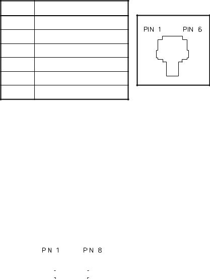
AudioAccessory/RS-232Port
IPE2500A contains an eight-pin modular desk mic port to provide audio accessory options. Possible accessories include desk mic, gooseneck mic, boom mic, headset, or footswitch. The port is also used as the connector to a PC for CARD Suite programming.
Mic Input |
|
Pin |
Function |
|||||||
|
|
|
|
|
|
|
|
|
|
|
Type: |
Passive input |
8 |
B+ OUT (through 10 ohm) |
|||||||
|
|
|
|
|
|
|
|
|
|
|
Input Impedance: |
>2k ohm |
7 |
RS-232 TX OUT |
|||||||
|
|
|
|
|
|
|
|
|
|
|
Nominal Input Level: |
−20 dBm |
6 |
Monitor IN (closure to ground) |
|||||||
|
|
|
|
|
|
|
|
|
|
|
Input Adjustment Range: |
N/A |
5 |
AGND |
|||||||
|
|
|
|
|
|
|
|
|
|
|
|
|
|
|
|
|
|
|
|
4 |
Mic IN (with bias voltage) |
|
|
|
|
|
|
|
|
|
||
|
|
|
|
|
|
|
|
|
|
|
|
|
|
|
|
|
|
|
|
3 |
PTT IN (closure to ground) |
|
|
|
|
|
|
|
|
|
||
|
|
|
|
|
|
|
|
|
||
|
|
|
|
|
|
|
|
|
|
|
|
|
|
|
|
|
|
|
|
2 |
RS-232 RX IN |
|
|
|
|
|
|
|
|
|
||
|
|
|
|
|
|
|
|
|
||
|
|
|
|
|
|
|
|
|
1 |
RX audio OUT (handset audio) |
|
|
|
|
|
|
|
|
|
|
|
7 |
03/12 |
Description |
IPE2500A and IPE2500A-MLS Paging Encoder/Desktop Controller |
Control Tones
Standard EIA tone keying tones are used for controlling the radio system. The sequence is:
A 2175 Hz High Level Guard Tone (HLGT) for 120 ms (default), programmable via CARD Suite.
One of 16 function tones (FT) is sent for 40 ms (default), programmable via CARD Suite.
The frequency range is from 2050 Hz to 550 Hz in 100 Hz steps. The FT level is 10 dB lower than the HLGT.
Monitor/F16 |
2050 |
F4 |
1650 |
F8 |
1250 |
F12 |
850 |
|
|
|
|
|
|
|
|
F1 |
1950 |
F5 |
1550 |
F9 |
1150 |
F13 |
750 |
|
|
|
|
|
|
|
|
F2 |
1850 |
F6 |
1450 |
F10 |
1050 |
F14 |
650 |
|
|
|
|
|
|
|
|
F3 |
1750 |
F7 |
1350 |
F11 |
950 |
F15 |
550 |
|
|
|
|
|
|
|
|
A 2175 Hz Low Level Guard Tone (LLGT) is generated for the duration of the transmission. The LLGT is not generated during monitor. Because voice is present with this LLGT, a 2175 Hz filtering is required in the tone panel.
When the monitor (CTCSS disable) is activated, the HLGT is generated for 120 ms, then a function tone of 2050 Hz is generated for 40 ms.
Tone Levels
Assuming that the ITA2000A Tone Remote Adapter has the HLGT output level set to 0 dBm:
The FT level and audio voice level are –10 dBm (10 dB below HLGT)
The LLGT level is –30 dBm.
The HLGT and FT durations are programmable.
Some tone panels use the value of the FT frequency to provide certain radio control functions. If the radio supports channel changes from an external logic source, the FT1 frequency of 1950 Hz could be used to change the radio to channel 1. An FT6 frequency of 1450 Hz could change the radio to channel 6. This operation is identified as “channel steering.”
DTMF Decode/H.E.A.R. System Support
The IPE2500A will decode incoming DTMF and display the ID numerically or as a preprogrammed alias. The DTMF decode function will provide H.E.A.R. system support using a base ID DTMF code to perform speaker un-muting and alert functions.
03/12 |
8 |

IPE2500A and IPE2500A-MLS Paging Encoder/Desktop Controller Description
Accessories
Description |
Part No. |
|
|
|
|
Desk Microphone (direct connection) |
XDM004A |
|
|
Desktop Gooseneck Microphone (requires XAAB002A) |
XDM005A |
|
|
Footswitch (requires XAAB002A) |
XFS002A |
|
|
Tone Remote Adapter |
ITA2000A |
|
|
Audio Accessory Box |
XAAB002A |
|
|
Amplified Headset, Single Earpiece (requires coiled cord) |
XHS003C |
|
|
Coiled Cord for XHS003C (requires XAAB002A) |
XCC004B |
|
|
Coiled Cord with PTT for XHS003C (requires XAAB002A) |
XCC003C |
|
|
External Speaker Kit (Unselect Audio for –MLS) |
XAC0120A |
|
|
Field Replacement Items
Description |
Part No. |
|
|
PTT Handset with Cord, Black |
HANDSET-BLACK |
|
|
Replacement Power Supply, 100–240 V ac/12 V dc |
40419-008 |
|
|
Power Supply Adapter, European |
40420-001 |
|
|
Power Supply Adapter, UK |
40420-002 |
|
|
Power Supply Adapter, Australia |
40420-003 |
|
|
Power Supply Adapter, Korea |
40420-004 |
|
|
Replacement Speaker Assembly |
61501-014 |
|
|
Replacement Main PCBA |
69295-003 |
|
|
Replacement Power Supply PCBA |
69298-001 |
|
|
Programming
Description |
Part No. |
|
|
Programming Bundle CD |
XAC4000A |
|
|
Programming Cable with Adapter |
XAC0004A |
|
|
9 |
03/12 |

Description IPE2500A and IPE2500A-MLS Paging Encoder/Desktop Controller
Performance Specifications
Color ..................................................................................................................................................... |
Black |
Physical size.................................................................................................... |
7.6 W 8.9 L 4.7 H inches |
Weight................................................................................................................................................ |
2.4 lbs. |
Temperature range ............................................................................................................. |
−35 C to +70 C |
Humidity ..................................................................................................... |
95% at 50 C (non-condensing) |
Line impedance............................................................................................................... |
600 ohms, nominal |
Power Input................................................... |
10.5 to 16 V dc; 500 mA maximum from supplied ac adapter |
Safety .............................................................................................. |
Class III SELV powered equipment. |
|
Powered by UL-listed (E104603) |
|
and CSA-certified (LR67888) Class 2 ac adapter. |
Emissions:....................................................................... |
USA: FCC Part 15, Sub. B- Verification. |
|
Canada: ICES – 003 |
Line Interface................................................................................................................ |
FCC Part 68 Exempt |
|
(Category II Tariff #260 service for private/leased line applications) |
|
Canada: IC CS03-8 |
Nominal input level ........................................................................................................................ |
−10 dBm |
Nominal output level ......................................................................................................................... |
−10 dB |
|
Range −14 to +12 dB into 560 ohms |
Frequency response................................................................... |
+3 dB, 300 to 3000 Hz (except notch filter) |
Hum and noise .................................................................................. |
Less than −45 dB below rated outputs |
Audio output to speakers ................................................. |
1 watt minimum with level in compression range |
Audio Distortion ............................................................................................................. |
Less than 3% THD |
Maximum number of remotes.................................................................................................................. |
Ten |
Control functions |
|
Guard tone ................................................................................................. |
2175 Hz, programmable |
F1–F16.................................... |
Each is programmable from 550 to 2050 Hz in 100 Hz increments |
Monitor ................................. |
2050 Hz, programmable from 550 to 2050 Hz in 100 Hz increments |
03/12 |
10 |

Operation
The IPE2500A provides radio system control from a remote location. It sends tone control to the remote adapter through a telephone line to control radio functions such as transmit, channel steering, and monitor.
Receive audio from the radio system is sent to the desk sets via the same line connection in two-wire applications, or by using another pair in four-wire applications.
The numeric keypad buttons are used for selection of different base station frequencies. These frequencies are dependent upon your radio’s capabilities. Changes to system parameters require the use of the CARD Suite Programming Software and the programming cable, which are sold separately. Complete information is contained in the “CARD Suite Programming Software” section of this manual.
Display
The IPE2500A has a backlit 2 16-character super-twist LCD display to provide valuable operator information. This information allows the operator to determine the status of the unit. The following describes the display at various states:
At power up:
Initially, line 1 shows: CHECKING PARAMS, and line 2 shows: PLEASE WAIT.
After 3 to 5 seconds, line 1 shows IPE2500, and line 2 shows: the firmware version.
During normal operation
Line 1 shows:
The currently selected frequency - FREQ:XX or the frequency alias, and
The current state of the unit - receive, RX; transmit, TX; intercom, IC; monitor, MON; alert, ALT; supervisory, SUP
Line 2 shows:
Speaker/handset audio level during a change of level
Current line selection and manual unselect audio mute status on an IPE2500-MLS
Paging information during page function
Operator instructions when applicable
During installation
The display shows various diagnostic information.
11 |
03/12 |
Operation |
IPE2500A and IPE2500A-MLS Paging Encoder/Desktop Controller |
Receiving Calls
When power is applied, the IPE2500A is in the receive mode, allowing receive audio to be heard through the speaker or handset. It is always in receive mode unless the unit is transmitting, or a parallel desk set is transmitting (parallel mute function enabled).
The IPE2500A Desk Set contains an internal or local speaker and a handset speaker that operate as follows:
When the handset is in the cradle, or on-hook, receive audio is heard on the internal speaker. In some operational modes, this can be changed, i.e., muting the speaker during TX of a parallel desk set.
When the handset is off-hook, receive audio is routed to the handset. By using the front panel buttons, you may optionally select to hear audio through the local speaker in addition to the handset.
Initiating Calls
Before initiating a call, press the MONITOR button to verify that the radio channel is clear. The MONITOR button remains illuminated until a transmit function is initiated. This operation is typically required when a community or shared repeater is in use. Always allow time for the radio channel to be established. In addition, if the unit is configured to generate PTT IDs and to generate side tone, a tone will be heard during the PTT pretime and PTT generation. A voice delay can be programmed via the CARD Suite software to eliminate this waiting time if no PTT ID is used.
To initiate a call, press the TRANSMIT button, the handset push-to-talk (PTT) pressbar, or an accessory PTT button. When the desk set is transmitting, the TRANSMIT LED illuminates. The TRANSMIT button or handset PTT bar must be held down while talking to the radio user and released to listen. When the transmission is completed, the TRANSMIT LED extinguishes and the desk set returns to the receive mode.
03/12 |
12 |
IPE2500A and IPE2500A-MLS Paging Encoder/Desktop Controller |
Operation |
Handset Transmit
Use of the handset is recommended when the desk set is located in noisy surroundings or if full-duplex two-wire operation is desired. This may be used for types of systems that provide talk courtesy tones, such as trunking. Press the handset PTT bar or TRANSMIT button and speak into the handset microphone to transmit when the handset is off-hook.
Transmit FromInternal (Local)Microphone
Use the internal microphone only in low noise environments. The handset must be on-hook for the local microphone to operate. Press the TRANSMIT button and speak in the direction of the integral microphone. For the best transmit audio quality, maintain a distance of about 18 inches from the microphone.
Transmit FromDeskMicrophoneor Footswitch
All models can be keyed to transmit with an external desk microphone through the audio accessory port. When a PTT signal is asserted through this port, TX audio will also originate through this port. Use of the GAI-Tronics XDM002A or XDM004A Desk Mic, or compatible microphone, is recommended.
NOTES:
1.The polarity of the desk mic PTT and monitor inputs is CARD Suite programmable. If the polarity of either of these inputs is set for normally closed, it is necessary to keep the desk microphone connected at all times. Removing the microphone during operation may cause the keyboard to stop responding. This is caused by the internal pull-ups on these two pins. If the desk mic maintains a normally closed connection to ground, the connection is opened when the button is pressed and the desk set recognizes the key as pressed. Without the desk mic connected, the connection remains open and the desk set continually sees the key pressed.
2.The IPE2500A has three microphone sensitivity adjustments. Refer to the “Installation” section of this manual.
13 |
03/12 |
Operation |
IPE2500A and IPE2500A-MLS Paging Encoder/Desktop Controller |
Front Panel Buttons
SignalingButtons
The signaling buttons operate as follows:
ALERT
The ALERT button is used to transmit two types of alert tones: a continuous tone and a pulsed tone (when used in conjunction with the CTL button.) Refer to the “Alert Tone” section on page 23 of this manual for a detailed description.
PAGE
The PAGE button is used to enter page mode. While in page mode, the operator may select from among various types of pages to be transmitted. These include DTMF, 2-Tone, Plectron, 5/6-Tone, 2805, 1500, and Immediate DTMF. Refer to the “Paging” section on page 24 of this manual for a detailed description.
CLEAR
The CLEAR button uses include clearing the frequency selection during frequency selection mode or clearing a capcode entry in paging mode.
SELECT
The SELECT button is used to enter the frequency selection mode (not possible on the IPE2500A-MLS), select a frequency in frequency selection mode or select a paging type in page mode.
UP/DOWN BUTTONS
The UP and DOWN buttons are used while in the paging mode to scroll through the pre-programmed paging aliases and for programming microphone sensitivity.
PB1, PB2, PB3, andPB4ProgrammableButtons
The four programmable buttons with LED indicators are used to custom configure up to eight user functions. The PB1 through PB4 buttons are accessed directly, while the PB5 to PB8 buttons are accessed using the CTL key while depressing one of the PB1 through PB4 buttons. When shipped from the factory, the programmable buttons are disabled. Refer to you CARD Suite Help file for programming information.
In addition, the use and function of these keys are dependent upon your radio’s capabilities.
VOLUMEUpandVOLUMEDownButtons
Press the VOLUME Up or Down buttons to adjust the local speaker volume if the handset is on-hook. The handset speaker volume is adjusted if the handset is off-hook.
The display shows the new setting for two seconds after a volume change. The internal, handset, and accessory each have individual settings. When the handset is off-hook, the following message is displayed:
HANDSET VOL: X (handset off-hook) |
SPEAKER VOL: X (handset on-hook) |
The VOLUME Up and VOLUME Down buttons also adjust the sensitivity of the microphone that is currently in use. Refer to the “Microphone Sensitivity Adjustments” section on page 44 of this manual for more information.
03/12 |
14 |
IPE2500A and IPE2500A-MLS Paging Encoder/Desktop Controller |
Operation |
Pressing the CTL + VOLUME Up buttons activates the internal speaker when the handset is off-hook. This can be used if others must hear the conversation. When the handset is returned to the cradle, this setting is reset so that if the handset is again removed from the cradle, the internal speaker is not active.
Pressing the CTL + VOLUME Down buttons mutes the internal speaker indefinitely. Pressing VOLUME Up, VOLUME Down, CTL + VOLUME Up, or removing the handset from the cradle and returning it resets the setting.
CTL(Control)Button
The CTL button, when used in conjunction with various other buttons, can perform additional features of the desk set.
IC (Intercom)Button
Use this button to communicate between desk sets without transmitting over the radio channel. When the IC button is pressed and held, microphone audio is routed to the line without activating the radio transmitter. Other desk sets on the same line will hear the audio automatically. Note that when configured for four-wire operation, the internal intercom path must be enabled by the CARD Suite software for parallel units to hear intercom audio.
MONITOR Button
When the MONITOR button is pressed, the desk set, adapter, and the radio are placed in the monitor mode (CTCSS/CDCSS disabled), the MONITOR LED illuminates, and the display indicates MON. Press this button before making a call to ensure a clear radio channel is available.
TRANSMIT Button
Press this button to place the desk set in the transmit mode. See the “Initiating Calls” section. When the TRANSMIT button is pressed, the TRANSMIT LED illuminates, and MONITOR LED extinguishes (if Monitor is selected prior to transmitting). The display indicates the mode and current frequency selected. In the IPE2500A, the TRANSMIT LED flashes when a parallel unit is transmitting. Transmission is not allowed in this state.
SELECT Button
When using the IPE2500A in normal operation, the SELECT button can be used to enter the frequency selection mode. If Direct DTMF dialing is enabled, this method and the use of programmable buttons are the only ways to change the selected frequency.
NOTE: The SELECT button cannot be used for this function on the IPE2500A-MLS.
KeypadButtons
The numeric keypad is used for the selection of a desired frequency page capcode entry and direct DTMF dialing. See “Numeric Keypad Frequency Selection,” “Paging” and “Direct DTMF Dialing” sections of the manual for further information.
15 |
03/12 |
Operation |
IPE2500A and IPE2500A-MLS Paging Encoder/Desktop Controller |
Parallel Status Operation
The IPE2500A supports parallel status updating. This feature allows all dispatch positions to know the status of the base station.
To decode this information, the unit senses high level guard tone (HLGT), then decodes the function tone that follows. Due to various tone control schemes supported by the unit, it is important to understand the rules of decoding the function tones.
1.If the monitor function is decoded, the unit is placed into the monitor mode. If any transmit function tone is programmed to be the same as the monitor function tone, that transmit tone will not be decoded.
2.If two transmit function tones are programmed to the same frequency, only the first of the tones in the sequence will be decoded; the subsequent transmit function tones set to the same frequency will not be decoded.
3.If a PTT function tone is programmed, it is not decoded since this does not contain channel control information. If a transmit function tone is programmed to be the same as the PTT function tone, the transmit function tone will not be decoded.
4.If a transmit function tone is programmed to be the same as a tone supervisor tone, the supervisor function will be decoded.
To illustrate, the priorities of the decode function are as follows:
Highest priority: |
Monitor Function Tone |
|
Supervisor On Function Tone |
|
Supervisor Off Function Tone |
|
PTT Function Tone |
Lowest priority: |
Transmit Function Tone (F1 to F15, F16 with Monitor disabled) |
NOTE: Parallel status update operation is not available with the IPE2500-MLS.
Frequency Display
When shipped from the factory, the LCD display shows FREQ: XX, with XX being 1 to 16, depending on the selected frequency.
Each time the IPE2500A is powered up, the status of the base/radio is unknown. The desk set LCD display flashes the last selected frequency when the unit was powered down. The display continues flashing until a transmission or frequency change is entered, or a parallel unit initiates a transmission or frequency change. Each time a guard tone is detected on the line, the desk set assumes the status of the base/radio is unknown until a function tone is decoded at the proper time.
Note that the display remains flashing even when a monitor command is initiated after power-up. This is because the monitor command does not control which frequency is being monitored and the state of the base/radio is still unknown.
Since the IPE2500A-MLS does not support parallel status updating, the displayed frequency or alias is never flashed. The operator must ensure that the base station is on the proper frequency.
03/12 |
16 |
IPE2500A and IPE2500A-MLS Paging Encoder/Desktop Controller |
Operation |
Numeric Keypad Frequency Selection
The IPE2500A can be configured for multiple frequency control with the CARD Suite Programming Software. When the desired frequency is selected using the numeric keypad, that frequency change command is sent to the base. Other parallel units will reflect the newly selected frequency. Note that if Direct DTMF is enabled, the numeric keypad is used for direct DTMF dialing. To select a frequency on an IPE2500A only, the operator must first press the SELECT button. To select a frequency when nine or fewer function tones are enabled, press the corresponding button 1 through 9 on the numeric keypad. The unit automatically sends the command when the key is pressed.
When ten or more frequencies are enabled, use keypad buttons 2 through 9 to select frequencies 2 through 9.
To select frequency 1, press 0, then 1.
To select frequencies 10 through 16, press 1, then press 0 through 6.
If a disabled frequency is selected, the display shows: DISABLED FREQ. Pressing CLEAR exits the frequency selection mode without changing the selected frequency. To scroll through the enabled frequencies display, press * to scroll down and # to scroll up.
After the desired frequency has been selected, the operator may:
Press SELECT to select the frequency and exit the frequency selection mode.
Press MONITOR to select the frequency, exit frequency selection mode, pause 250 ms and send a monitor burst to monitor the newly selected frequency.
Press and hold TRANSMIT or the handset PTT bar to select the new frequency, exit the frequency selection mode and begin transmitting on the newly selected frequency.
PTT Function Tone (Key-up Only Function Tone)
This feature, compatible with tone and optional E&M with tone control, allows the desk sets to use only a single function tone burst generation when a voice transmission is required. The parallel status updating function is also modified. This is useful when the base station is only capable of one frequency control or when wildcard frequency keying is required.
When a frequency change command is sent, the desk sets generate normal HLGT and frequency function tones.
When the monitor function is sent, the normal monitor command is sent.
When a voice transmission is required, the HLGT and programmed PTT function tone is sent as the transmit command. No channel frequency function tones are used during a voice transmission.
When a parallel unit transmission is detected, the parallel status updates the selected function tone only if the frequency falls within programmed function tone frequencies. When a parallel PTT function tone is detected, the function tone of the unit is not updated and continues to be unknown (flashes) until a frequency change command is detected.
17 |
03/12 |
Operation |
IPE2500A and IPE2500A-MLS Paging Encoder/Desktop Controller |
Tone Supervisor Control
The IPE2500A offers a tone supervisor control feature which locks out transmission of parallel units upon detection of the proper tone control sequence. This feature cannot be activated during a parallel transmission. The supervisor unit is programmed with appropriate on/off frequencies and a supervisor button. Parallel, non-supervisor units are programmed with the same on/off frequencies.
When the supervisor unit operator presses the supervisor button and turns on the supervisor function, programmed parallel units will not allow any transmission and their keyboards will be locked. The display flashes SPV until the supervisor turns the function off.
The IPE2500A can optionally be configured for relay controlled supervisor using a relay programmable button.
“Hard” Supervisor Control
To ensure parallel units are locked out of transmission upon demand by the supervision position, the relay I/O module should be used and the supervisor unit placed closest to the transmitter or adapter. Note that tone supervisor cannot be activated during a parallel transmission.
Secure Operation
When using Tone or E&M with Tone control, it is possible to use two-function tone generation to adapt to certain secure capable systems. Parallel status does not support this mode of operation.
In this configuration, the IPE2500A generates a HLGT, a coded/clear function tone, then the channel control function tone. Each of the coded and clear function tones are programmable to the same frequencies as the channel control function tones and is the same level.
NOTE: A programmable button should be used to toggle the state of the unit from coded to clear transmission mode.
By adding factory or field-installed options, other types of control, besides tone, may be used.
03/12 |
18 |
IPE2500A and IPE2500A-MLS Paging Encoder/Desktop Controller |
Operation |
DTMF Decode
The DTMF decoder is primarily used for automatic number identification, or ANI, by the dispatch operator. ANI is used to communicate to a dispatcher the identity of the transmitting radio. This use of DTMF is transmitted only in one direction without the receiving unit acknowledging the receipt of information.
When the field unit presses the PTT button of the radio, the radio generates a preprogrammed sequence of DTMF digits prior to opening the voice path of the radio. The IPE2500A decodes these digits and displays the ID either numerically or with a preprogrammed alias. The dispatcher then knows, without the field radio user having to speak his identity, which radio is being received.
H.E.A.R. System Operation
The H.E.A.R. (Hospital Emergency Administration Radio) system operation is typically used in hospital emergency rooms. During H.E.A.R. operation, the internal speaker of the IPE2500A would typically be muted so that normal radio traffic is not heard in the emergency room. A DTMF sequence is transmitted, prior to voice transmission, by ambulance or public safety personnel to access the emergency room’s radio system.
To perform H.E.A.R. functions, the desk set contains a base ID used to deactivate the speaker mute. When the desk set decodes a valid DTMF sequence, it compares the sequence to the H.E.A.R. base ID. If the ID matches, the desk set unmutes the speaker, allowing received audio to be heard by emergency room personnel. The unit must be returned to mute mode manually.
The speaker mute is achieved by programming a mute button using the programmable buttons found on the front panel of the IPE2500A. An optionally installed H.E.A.R. system relay and/or audible 2 kHz alert tone of programmable duration can also be programmed for activation upon receipt of the proper base ID. Refer to the CARD Suite Help file for detailed programming instructions.
NOTE: H.E.A.R. System operation or DTMF Decode is not available with the IPE2500A-MLS.
19 |
03/12 |
Operation |
IPE2500A and IPE2500A-MLS Paging Encoder/Desktop Controller |
Optional DC Control Kit
NOTE: This optional feature requires the XDC0001A DC Control Kit and XAC0100A Mounting Kit.
DC currents from +14 to –14 mA in 0.5 mA increments are used to control radio functions. Parameters for dc control are set using the programming software. However, the accuracy of the adjustments may be affected by line loads and installations. In order to work properly with varying line loads and dc remote adapters, the time the current is present before allowing key-down may be programmed with the software. Appropriate settings ensure the state of the remote adapter can be assured when a frequency change current is asserted.
NOTE: JU1 on the power I/O board (DPS) must be “out” for DC Control.
Optional Relay Control Kit
NOTE: These optional features require the XRC0001A Relay Control Kit and XAC0100A Mounting Kit.
The CARD Suite programming software can be used to assign the type of configuration desired. It can be configured as E&M control, local, or E&M with Tone control. Two pair of leads controls communication between the IPE2500A and the base station. Maximum load ratings for each relay output are 1 A @ 125 V ac and 2 A @ 30 V dc.
Local Control
For applications where the radio is connected directly to desk set units on-site, the unit must be configured for local control. Also, a PTT and monitor relay must be programmed with the CARD Suite, and these connections must be made to the relays.
E&M
The CARD Suite can be used to configure the IPE2500A for E&M control. The unit can be configured for either E&M control or E&M with tone control. Two pairs of leads control communication between the desk set and the base station. One pair is dedicated to audio TX/RX, the other pair controls the E&M signaling.
The IPE2500A uses the M lead to signal when to transmit, and the E lead to detect when to receive. Note that the E lead is not required. The M lead must be set on relay module using the CARD Suite software.
ELead
In systems requiring full-featured E&M control, the input can be configured as an E lead to indicate an unsquelched condition. The IPE2500A uses this input as a VOX indicator, so when asserted, generates a VOX condition. However, the speaker squelch is operated by voice activity.
MLead
A closure is needed to act as the M lead, which is the relay closure. The M lead will be closed depending on the type of configuration and the type of transmission, only during a non-intercom transmission.
When configured as E&M control, the relay will be closed only when a transmission requiring transmitter keying is needed.
When configured as E&M with Tone control, the relay will be closed whenever a non-intercom transmission is done.
03/12 |
20 |
IPE2500A and IPE2500A-MLS Paging Encoder/Desktop Controller |
Operation |
E&MwithToneControl
Used for transmitting control tones using an RF device in lieu of a telephone line. Two pair of leads control the high level guard tone, function tone and low level guard tone. The tones are generated by the IPE2500A to base stations via the E&M leads.
The M lead is used to assert PTT of the device, allowing transmission of the control tones to a remote adapter with a receiving RF device. The unit must be configured for E&M with Tone control and M lead must be set on relay mode. Note that the HLGT duration may need to be increased to allow the RF device time to keep up and transmit to the receiving device.
Multi-line Select (IPE2500A-MLS)
NOTES:
1.This operation requires IPE2500A-MLS Desk Set or XMLS001A Field Install Kit and XAC0100A Mounting Kit.
2.With the MLS option installed, the DC and Relay options cannot be used.
3.With the MLS option, the SELECT button cannot be used to enter the frequency selection mode.
The multi-line select operation allows the unit to control up to four base stations with one tone remote unit. This feature is provided standard with the IPE2500A-MLS, and can be added to the IPE2500A via the XMLS001A 4-Line Field Install Kit. The features include:
Tone remote control of two to four different base stations
Vox-detect indication for each line
Unselect audio reference adjustment
Multi-select transmission
Mute unselect audio on transmit
Unselect audio mute using a programmable button
Two-wire or four-wire compatible
NOTE: The addition of the line select option to the IPE2500A allows the unit to control multiple base stations with one unit using tone remote control. The option is not compatible with dc or local control configurations.
Since the option is an ancillary device, some limitations are imposed on the operation of the unit. These limitations include:
The LOTL detection and parallel status updating features of the IPE2500A are not available when the multi-line select option is installed because the IPE2500A receives a sum of the select and unselect audio and cannot distinguish the source of the audio.
During multi-select transmissions, the same control tones are used on each line. The unit is not capable of generating different function tones on each line during a multi-select transmission.
The channel aliases are shared among all lines.
The volume control becomes a master volume for select and unselect audio. The relative level of the unselect audio to the select audio can be adjusted during operation.
DTMF Decode is not available.
H.E.A.R. operation is not available.
21 |
03/12 |
 Loading...