


ENCOUNTER
ENCOUNTER
AMPLIFIER MANUAL
EN-
 1502 EN-
 3001 EN-
 3004
3004

ENGLISH
AMPLIFIER SPECIFICATIONS
|
EN-3004 (4 Channel) |
EN-1502 (2 Channel) |
Class |
Class-AB |
Class-AB |
|
|
|
Power |
1800 Watts |
1000 Watts |
|
|
|
Frequency Response |
20Hz - 20kHz |
20Hz - 20kHz |
|
|
|
Dimensions |
336mm (13-1/4”) x 200mm (7- |
256mm (10-1/16”) x 200mm (7- |
|
7/8”) x 51mm (2”) |
7/8”) x 51mm (2”) |
|
|
|
RMS Power Ratings |
60 Watts x 4 @ 4 Ohms 1% THD+N |
60 Watts x 2 @ 4 Ohms 1% THD+N |
|
75 Watts x 4 @ 2 Ohms 1% THD+N |
75 Watts x 2 @ 2 Ohms 1% THD+N |
|
150 Watts x 2 @ 4 Ohms Bridged |
150 Watts x 1 @ 4 Ohms Bridged |
|
1% THD+N |
1% THD+N |
|
|
|
Signal to Noise Ratio |
>50 dB |
>50 dB |
|
|
|
High and Low Pass |
12dB per Octave |
12dB per Octave |
Crossover |
|
|
|
|
|
Crossover Range |
50Hz – 250Hz |
50Hz – 250Hz |
|
|
|
Low Level Input Range |
0.35 Volts to 10 Volts |
0.35 Volts to 10 Volts |
|
|
|
High Level Input Range |
1 Volt to 30 Volts |
1 Volt to 30 Volts |
|
|
|
Minimum load |
2 Ohm stereo and 4 Ohm bridged |
2 Ohm stereo and 4 Ohm bridged |
impedance |
|
|
|
|
|
|
EN-3001 (Monoblock) |
Class |
Class-AB |
|
|
Power |
1200 Watts |
|
|
Frequency Response |
20Hz - 400Hz |
|
|
Dimensions |
336mm (13-1/4”) x 200mm (7- |
|
7/8”) x 51mm (2”) |
|
|
RMS Power Ratings |
200W x 1 @ 4 Ohms 1% THD |
|
300W x 1 @ 2 Ohms 1% THD |
|
|
Signal to Noise Ratio |
>50 dB |
|
|
High and Low Pass |
12dB per Octave |
Crossover |
|
|
|
Subsonic Filter |
12dB per Octave |
|
|
Low Pass Crossover |
50Hz – 400Hz |
Range |
|
|
|
Subsonic Crossover |
10Hz – 40Hz |
Range |
|
|
|
Bass Boost @ 45Hz |
0 to +18dB |
|
|
Low Level Input Range |
0.35 Volts to 10 Volts |
|
|
High Level Input Range |
1 Volt to 30 Volts |
|
|
Minimum load |
2 Ohm |
impedance |
|
|
|
|
General |
|
|
Power |
+12 V DC (negative |
Requirements |
ground) |
|
|
Operating Voltage |
10.5 – 16V |
|
|
Minimum |
8 Gauge (AWG) |
Recommended- |
|
Power/Ground |
|
Cable Size |
|
|
|
Recommended |
8 Gauge Cable - 40A |
inline fuse size |
4 Gauge Cable - 80A |
|
|
NOTE: ENCOUNTER AMPLIFIER SERIES HAVE A MINIMUM LOAD IMPEDANCE OF
2 OHM PER CHANNEL
4 OHM BRIDGED
Version 2.1
2

AMPLIFIER INSTALLATION
INSTALLATION WARNINGS
1.Ensure the +12V lead is disconnected from the battery before you connect any new equipment.
2.Ensure that the amplifier mounting location and holes will not interfere with the gas tank, brake lines or electrical wiring.
3.Ensure the amplifier is securely fastened to the vehicle to prevent the amplifier moving and causing damage in the event of an accident.
4.Ensure all wiring is protected from sharp objects and from pinching or crushing which could result in damage to the audio system.
5.Ensure the mounting location has sufficient air flow around the amplifier. If the amplifier is mounted in an enclosed space a 3” fan with ducting should be used to assist with cooling.
6.Do not mount any amplifier on a subwoofer enclosure as extended exposure to vibration may cause damage to the amplifier.
7.Ensure you use the minimum recommended gauge wire/cable or larger for all amplifier connections.
8.Appropriate mounting is very important for prolonged life expectancy of any amplifier. Select a location that provides protection from moisture. Keep in mind that an amplifier should never be mounted upside down. Upside down mounting will compromise heat dissipation through the heat sink and could engage the thermal protection circuit.
CONNECTION
Ensure the audio system is turned off before making any connections to the amplifier, speakers or source unit. Failure to do so could result in permanent damage to the audio system.
Ensure the correct gauge cable is used for all connections; consult the cable calculator diagram below for the correct gauge cable for your installation.
TOTAL |
|
CABLE |
M |
0 - 1 |
1 - 2 |
2 - 3 |
3 - 4 |
4 - 5 |
5 - 6 |
6 - 7 |
7 - 9 |
|
AMPS |
LENGTH |
|
|
|
|
|
|
|
|
|
||
FT |
0- 4 |
4 - 7 |
7 - 10 |
10 - 13 |
13 - 16 |
16 - 19 |
19 - 22 |
22 - 28 |
||||
|
|
> |
||||||||||
|
|
|
|
|
|
|
|
|
|
|
||
|
|
|
|
|
|
|
|
|
|
|
||
0 - 20 |
|
14 |
12 |
12 |
10 |
10 |
8 |
8 |
8 |
|||
|
|
|
|
|
|
|
|
|
|
|
||
20 |
- 35 |
|
12 |
10 |
8 |
8 |
6 |
6 |
6 |
4 |
||
|
|
|
|
|
|
|
|
|
|
|||
35 - 50 |
|
10 |
8 |
8 |
6 |
4 |
4 |
4 |
4 |
|||
|
|
|
|
|
|
|
|
|
|
|||
50 - 65 |
|
8 |
8 |
6 |
4 |
4 |
4 |
4 |
2 |
|||
|
|
|
|
|
|
|
|
|
|
|||
65 - 85 |
|
6 |
6 |
4 |
4 |
2 |
2 |
2 |
0 |
|||
|
|
|
|
|
|
|
|
|
|
|||
85 - 105 |
|
6 |
6 |
4 |
2 |
2 |
2 |
2 |
0 |
|||
|
|
|
|
|
|
|
|
|
|
|
||
105 |
- 125 |
|
4 |
4 |
4 |
2 |
0 |
0 |
0 |
0 |
||
|
|
|
|
|
|
|
|
|
|
|
||
125 |
- 150 |
|
2 |
2 |
2 |
0 |
0 |
0 |
0 |
0 |
||
|
|
|
|
|
|
|
|
|
|
|
|
|
The above chart shows cable gauges to be used, if no less than a 0.5 volt drop is acceptable. If aluminium wire is used, the gauges should be of an even larger size to compensate. Cable gauge size calculation takes into account terminal connection resistance.
3
AMPLIFIER CONNECTONS
1. +12V POWER
|
|
|
|
|
|
Ensure ALL other cable connections are |
|
|
|
|
|
|
|
completed before connecting this cable to the |
|
|
|
|
|
|
|
||
|
|
|
|
|
|
battery. FUSION amplifiers should be connected |
|
|
|
|
|
|
|
directly to the 12v battery terminal using the |
|
|
|
|
|
|
|
appropriate gauge cable. Start at the vehicles |
|
1 |
2 |
3 |
|||||
battery and run the cable through to the |
|||||||
EN-1502 EN-3004 EN-3001 |
amplifier. FUSION recommends the use of rubber |
||||||
grommets when passing any cable through metal |
|||||||
panels to avoid sharp corners or panels that could cut through the insulation of the cable. Avoid running any cables near engine components or heater cores. An in line fuse or circuit breaker MUST be used within 30cm (12”) of your battery; this will prevent the potential risk of a fire caused by a short in your power cable (see specifications table for recommended in line fuse / circuit breaker ratings). Connect the other end of your power cable to the battery, but remember to leave the fuse out or circuit breaker off until all other cable connections are made.
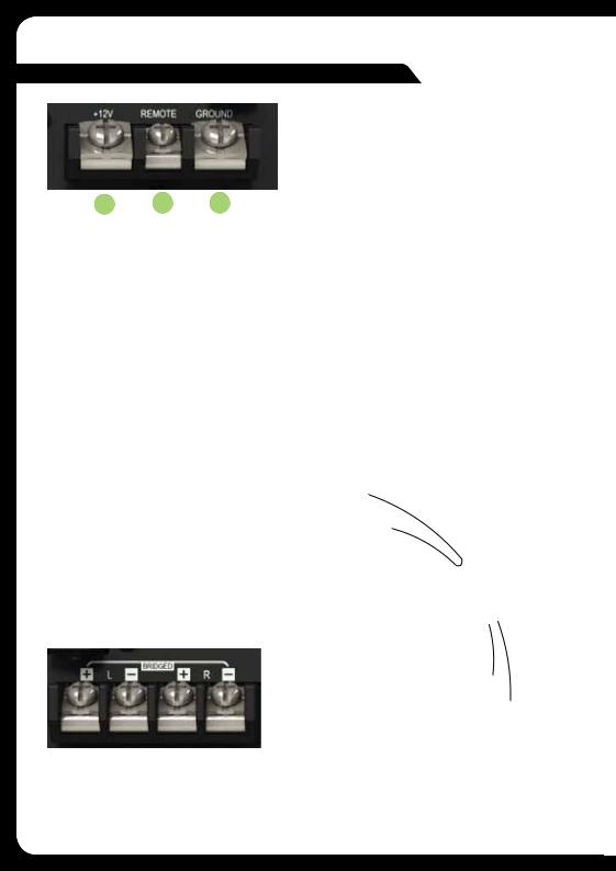
2. REMOTE TURN ON
This connection turns the amplifier on and should be connected to the “Remote turn on” wire from the Head Unit. If one is not available a switched +12v source must be used, such as a power antenna wire or ACC +12v.
If you are using high level (speaker) inputs and a remote turn on wire is not available, then the “Auto Turn-On” switch must be set to audio.
3. GROUND
Connect the Ground/Earth cable for your amplifier first. Ensure that the location is a good source of ground (preferably the chassis / floor pan). Investigate the area you wish to use to ensure it is free from wiring, vacuum lines, brake and fuel lines. Use either a wire brush or sandpaper to expose bare metal, this will provide a high current contact for your ground connection. Use the same gauge cable for the ground cable as you did for the power cable. Secure the ground cable to the ground point with a bolt, star washer and nut. Apply some neutral cure silicon to the bolt and bare metal to prevent possible water leaks and rust. Connect the other end of your ground cable to the amplifier. 
4A. SPEAKER OUTPUT CONNECTION
Ensure the correct polarity is observed when connecting speakers/subwoofers.
2 Ohm minimum speaker impedance for stereo operation (per channel)
EN-1502 |
4 Ohm minimum speaker impedance for Bridged operation.
4
EN-3001
EN-3004
2 x Speakers
Front Channels
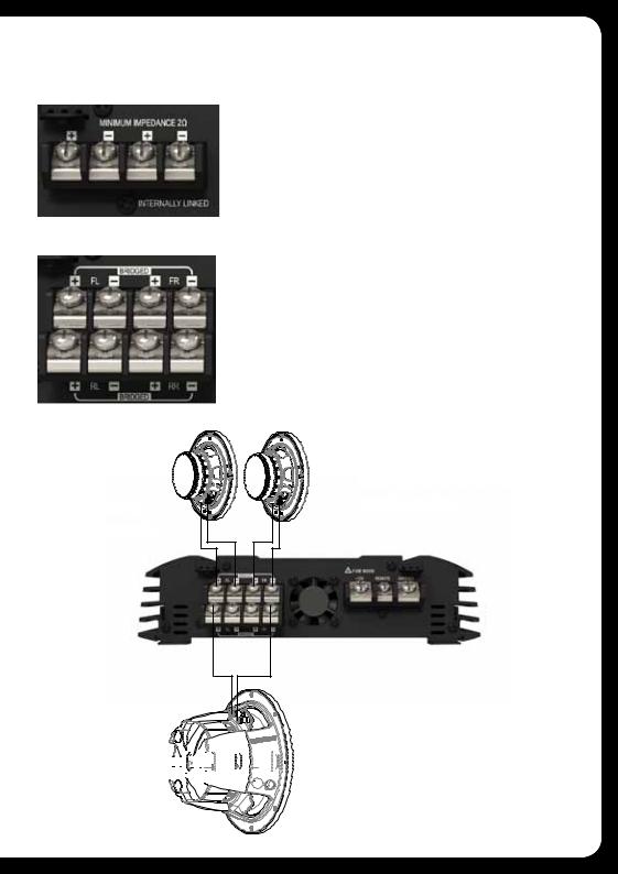
4B. INTERNALLY LINKED OUTPUT (EN-3001 ONLY) - COILS IN PARALLEL
The EN-3001 Monoblock amplifier provides dual output connections to simplify wiring when using two subwoofers or a dual voice coil subwoofer. Both positive and negative terminals are internally connected or linked in parallel. For dual coil (2 x 4 Ohm) or two single coil (4 Ohm) subwoofers, connect each coil to a positive and negative terminal. For a standard single coil subwoofer connect to either positive and either negative terminal.
4C. BRIDGED CONNECTION (EN-1502 AND EN-3004)
By connecting a speaker or subwoofer to the positive terminal of one channel and the negative of the other channel, you are combining the output of two channels into one. This gives you higher output levels as noted in the specifications but you must observe the minimum load impedance as failure to do so will result in damage to the amplifier.
EN-3004
Example of 3 channel configuration.


 (4 Ohm Subwoofer)


 Bridged rear channels
5
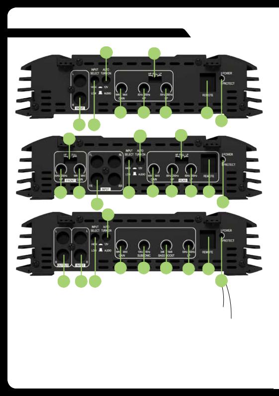
AMPLIFIER CONTROLS
15 10
|
7 |
8 |
9 |
13 |
5 14 |
EN-1502 |
|
16 |
|
|
|
|||
10 |
|
15 |
|
10 |
|
|
|
|
|
8 |
7 |
14 |
7 |
8 |
9 |
13 |
|
5 |
EN-3004 |
|
|
16 |
|
|
|
15 |
|
|
|
|
7 11 12 9 13
6 5 14 |
EN-3001 |
16 |
5. LOW LEVEL RCA INPUTS FRONT-REAR-SUBWOOFER
Choose the correct length RCA cables to connect the RCA outputs of the source/head unit, to the input connectors of the amplifier. Run the RCA cables on the opposite side of the vehicle to the power cable and vehicle wiring loom. Avoid the electric fan motor and wiring. Ensure you follow the correct balance. (L Left = White or Black. R Right = Red).
6. LOW LEVEL RCA OUTPUTS (EN-3001 ONLY)
Use these RCA connectors to connect to a secondary amplifier. This output is a
pass-thru connection from the RCA input connectors so that the signal level and frequency response is the same as the original input signal.
6
 Loading...