


 Loading...

IMPORTANT NOTICES
General
•The operator of this equipment must read and follow the descriptions in this manual. Wrong operation or maintenance can cancel the warranty or cause injury.
•Do not copy any part of this manual without written permission from FURUNO.
•If this manual is lost or worn, contact your dealer about replacement.
•The contents of this manual and equipment specifications can change without notice.
•The example screens (or illustrations) shown in this manual can be different from the screens you see on your display. The screens you see depend on your system configuration and equipment settings.
•Save this manual for future reference.
•Any modification of the equipment (including software) by persons not authorized by FURUNO will cancel the warranty.
•All brand and product names are trademarks, registered trademarks or service marks of their respective holders.
How to discard this product
Discard this product according to local regulations for the disposal of industrial waste. For disposal in the USA, see the homepage of the Electronics Industries Alliance (http://www.eiae.org/) for the correct method of disposal.
How to discard a used battery
Some FURUNO products have a battery(ies). To see if your product has a battery(ies), see the chapter on Maintenance. Follow the instructions below if a battery(ies) is used.
In the European Union |
|
|
The crossed-out trash can symbol indicates that all types of |
|
|
batteries must not be discarded in standard trash, or at a |
|
|
trash site. Take the used batteries to a battery collection site |
|
|
according to your national legislation and the Batteries |
|
|
Directive 2006/66/EU. |
|
Cd |
In the USA |
|
|
The Mobius loop symbol (three chasing arrows) indicates that |
|
|
Ni-Cd and lead-acid rechargeable batteries must be recycled. |
|
|
Take the used batteries to a battery collection site according to |
Ni-Cd |
Pb |
local laws. |
In the other countries
There are no international standards for the battery recycle symbol. The number of symbols can increase when the other countries make their own recycling symbols in the future.
i

 SAFETY INSTRUCTIONS
The operator must read the safety instructions before attempting to operate this equipment
Indicates a potentially hazardous situation which, if not avoided, WARNING could result in death or serious injury.
CAUTION |
Indicates a potentially hazardous situation which, if not avoided, |
|
can result in minor or moderate injury. |
|
|
|
|
|
Warning, Caution |
Prohibitive Action |
Mandatory Action |
|
|
|
 WARNING
ELECTRICAL SHOCK HAZARD
Do not open the equipment.
Only qualified personnel should work inside the equipment.
The antenna emits electromagnetic radio frequency (RF) energy, which can be harmful. Distances at which RF radiation level of 100, 10 and 2 W/m2 are present are given below.
100 W/m2: |
Nil |
10 W/m2: |
0.1 m |
2 W/m2: |
1.0 m |
Immediately turn off the power at the switchboard if water leaks into the equipment or something is dropped in the equipment.
Continued use of the equipment can cause fire or electrical shock. Contact a FURUNO agent for service.
Do not disassemble or modify the equipment.
Fire, electrical shock or serious injury can result.
Do not place liquid-filled containers on the top of the equipment.
Fire or electrical shock can result if a liquid spills into the equipment.
Use the proper fuse.
Use of the wrong fuse can cause fire or permanent damage to the equipment.
 WARNING
Immediately turn off the power at the switchboard if the equipment is emitting smoke or fire.
Continued use of the equipment can cause fire or electrical shock. Contact a FURUNO agent for service.
Make sure no rain or water splash leaks into the equipment.
Fire or electrical shock can result if water leaks in the equipment.
Do not operate the equipment with wet hands.
Electrical shock can result.
WARNING LABEL
A warning label is attached to the AC-DC power supply. Do not remove the label.
If the label is missing or damaged, contact a FURUNO agent or dealer about replacement.
WARNING |
Name: Warning Label (1) |
|
Type: 86-003-1011-1 |
||
To avoid electrical shock, do not |
||
remove cover. No user-serviceable |
Code No.: 100-236-231 |
|
parts inside. |
|
ii

TABLE OF CONTENTS
FOREWORD........................................... |
iv |
||
SYSTEM CONFIGURATION .................. |
vi |
||
PROGRAM NUMBER ........................... |
vii |
||
SYSTEM OVERVIEW........................... |
viii |
||
1. OPERATION .................................... |
1-1 |
||
1.1 |
Description of Controls.............................. |
1-1 |
|
1.2 |
Turning the Power On and Off .................. |
1-2 |
|
1.3 |
Adjusting Panel Dimmer and Contrast ...... |
1-4 |
|
1.4 |
Menu Overview......................................... |
1-5 |
|
|
1.4.1 |
Menu operating procedure............ |
1-5 |
1.5 |
Entering Voyage-Related Data.................. |
1-7 |
|
1.6 |
Setting CPA/TCPA .................................. |
1-11 |
|
1.7 |
Selecting a Display ................................. |
1-12 |
|
|
1.7.1 |
Plotter display ............................. |
1-13 |
|
1.7.2 |
Target list (displaying target data)1-15 |
|
|
1.7.3 |
Dangerous (target) list ................ |
1-22 |
|
1.7.4 |
Static data display....................... |
1-22 |
|
1.7.5 |
Dynamic data display.................. |
1-24 |
|
1.7.6 |
Alarm status display.................... |
1-24 |
1.8 |
Messages ............................................... |
1-25 |
|
|
1.8.1 |
Sending a message .................... |
1-25 |
|
1.8.2 |
Receiving messages................... |
1-27 |
|
1.8.3 |
TX and RX message logs ........... |
1-29 |
1.9 |
Regional Operating Channels ................. |
1-30 |
|
|
1.9.1 |
Viewing channels, Tx power ....... |
1-30 |
|
1.9.2 |
Displaying, editing regional |
|
|
|
operating area status ................ |
1-31 |
1.10 |
Enabling/Disabling Alarm Buzzer, |
|
|
|
Key Beep............................................... |
1-34 |
|
1.11 |
Long Range Mode ................................. |
1-35 |
|
1.12 |
Viewing Initial Settings ........................... |
1-37 |
|
2. INLAND AIS OPERATION............... |
2-1 |
||
2.1 |
Activating the Inland AIS ........................... |
2-1 |
|
2.2 |
Selecting AIS Mode................................... |
2-2 |
|
2.3 |
Entering Voyage-Related Data.................. |
2-3 |
|
2.4 |
Static Data................................................. |
2-8 |
|
2.5 |
Dynamic Data ......................................... |
2-10 |
|
2.6 |
Details Ship Display (Mobile Class A) ..... |
2-11 |
|
2.7 |
Inland AIS Specific Messaging................ |
2-13 |
|
|
2.7.1 |
Text message.............................. |
2-13 |
|
2.7.2 |
ETA and RTA messages ............. |
2-15 |
|
2.7.3 No. of persons message............. |
2-19 |
|
|
2.7.4 |
EMMA warning message ............ |
2-21 |
|
2.7.5 |
Water level message .................. |
2-23 |
|
2.7.6 |
Message logs.............................. |
2-24 |
2.8 |
Viewing Initial Settings ............................ |
2-26 |
|
3. MAINTENANCE, TROUBLE- |
|
SHOOTING ...................................... |
3-1 |
3.1 Maintenance ............................................. |
3-1 |
3.2Replacement of Fuse, Resetting the
|
Breaker.................................................... |
3-2 |
|
|
3.2.1 |
Replacement of fuse..................... |
3-2 |
|
3.2.2 |
Resetting the breaker ................... |
3-2 |
3.3 |
Troubleshooting ........................................ |
3-3 |
|
3.4 |
Diagnostics ............................................... |
3-3 |
|
|
3.4.1 |
Monitor unit test ............................ |
3-3 |
|
3.4.2 |
Transponder test........................... |
3-5 |
|
3.4.3 |
Power on/off history ...................... |
3-7 |
|
3.4.4 |
Tx on/off history ............................ |
3-7 |
3.5 |
Alarm Status.............................................. |
3-8 |
|
3.6 |
Error and System Messages..................... |
3-9 |
|
3.7 |
GPS Monitor ........................................... |
3-11 |
|
3.8 |
Displaying Sensor Status ........................ |
3-12 |
|
3.9 |
Restoring Default Settings ...................... |
3-13 |
|
3.10 |
AIS-SART Test Indication in Target List.. 3-14 |
||
APPENDIX........................................ |
AP-1 |
Menu Tree - Class A AIS ................................. |
AP-1 |
Menu Tree - Inland AIS ................................... |
AP-3 |
Parts List ......................................................... |
AP-5 |
Parts Location ................................................. |
AP-6 |
Monitor unit ............................................ |
AP-6 |
Transponder unit .................................... |
AP-6 |
Digital Interface (IEC 61162-1 Edition 2, IEC |
|
61162-2) ...................................................... |
AP-8 |
Sentence data........................................ |
AP-8 |
Serial interface I/O circuit ....................... |
AP-9 |
Sentence description............................ |
AP-10 |
Inland AIS specific sentences............... |
AP-24 |
VHF Channel List .......................................... |
AP-27 |
International mode ............................... |
AP-27 |
USA mode............................................ |
AP-28 |
ERI Codes..................................................... |
AP-29 |
Terminology, Units, Symbols ......................... |
AP-30 |
SPECIFICATIONS ............................ |
SP-1 |
INDEX ................................................. |
IN-1 |
iii

FOREWORD
A Word to the Owner of the FA-150
FURUNO Electric Company thanks you for purchasing the FA-150 UAIS Transponder. We are confident you will discover why the FURUNO name has become synonymous with quality and reliability.
For over 60 years FURUNO Electric Company has enjoyed an enviable reputation for quality and reliability throughout the world. This dedication to excellence is furthered by our extensive global network of agents and dealers.
Your equipment is designed and constructed to meet the rigorous demands of the marine environment. However, no machine can perform its intended function unless properly operated and maintained. Please carefully read and follow the operation and maintenance procedures in this manual.
We would appreciate feedback from you, the end-user, about whether we are achieving our purposes.
Thank you for considering and purchasing FURUNO.
Features
The FA-150 is a universal AIS (Automatic Identification System) for open sea and inland waterways, capable of exchanging navigation and ship data between own ship and other ships or coastal stations. It complies with IMO MSC.74(69) Annex 3, A.694, ITU-R
M.137-3 and DSC ITU-R M.825. It also complies with IEC 61993-2 (Type testing standard), IEC 60945 (EMC and environmental conditions).
The FA-150 consists of VHF and GPS antennas, a transponder unit, a monitor unit, and several associated units. The transponder contains a VHF transmitter, two TDMA receivers on two parallel VHF channels, a DSC channel 70 receiver, interface, communication processor, and internal GPS receiver. The internal GPS is a 12-channel all-in-view receiver with a differential capability, and provides UTC reference for system synchronization to eliminate clash among multiple users. It also gives position, COG and SOG when the external GPS fails.
iv
The main features are
•Safety of navigation by automatically exchanging navigational data between ships and between ship and coast
•Static data:
-MMSI (Maritime Mobile Service Identity)
-IMO number (where available)
-Call sign & name
-Length and beam
-Type of ship
-Location of position-fixing antenna on the ship
•Dynamic data:
-Ship’s position with accuracy indication and integrity status
-Universal Time Coordinated (UTC)
-Course over ground (COG)
-Speed over ground (SOG)
-Heading
-Rate of turn (ROT) where available
•Voyage-related data
-Ship’s draught
-Navigation status (manual input)
-Hazardous cargo (type)
-Destination and ETA (at master’s discretion)
•Short safety-related messages, free messages
•LCD panel satisfies the IMO minimum requirements plus simple plotting modes
•Interfaces for radar, ECDIS, PC for future networking expansion
•GPS/VHF combined antenna for easy installation available
•CPA/TCPA alarm
•Built-in GPS receiver for UTC synchronization and backup position-fixing device
•The Inland AIS feature is based on CCNR (Vessel Tracking and Tracing Standard for Inland Navigation). Inland AIS receives and sends SOLAS AIS information, and interfaces automatic data input such as blue sign, draught (in centimeters), air draught (height from waterline), hazardous cargo blue cone indication, euro ship identifier and inland ship type. Further, the inland AIS sends ETA (Estimated Time of Arrival) to lock, bridge, terminal, etc. and displays response as RTA (Requested Time of Arrival) from the lock, bridge or terminal. Information receivable from land stations include EMMA warning, water level data, etc.
v
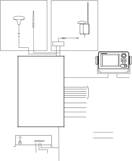
SYSTEM CONFIGURATION
|
|
|
|
Either |
|
GPS antenna |
VHF antenna |
|
GSC-001 |
||
GPS/VHF |
||
GPA-017S |
||
combined antenna |
||
|
||
|
GVA-100 |
|
|
|
|
|
|
|
|
|
|
|
|
|
|
MONITOR UNIT |
|
|
|
|
|
|
|
|
|
|
|
|
|
|
|
|
|
|
|
|
|
|
Distributor unit |
FA-1502 |
||||||
|
|
|
|
|
|
|
||||||||
|
|
|
|
|
|
|
(two units may |
|||||||
|
|
|
|
|
|
|
DB-1 |
|||||||
|
|
|
|
|
|
|
be connected) |
|||||||
|
|
|
|
|
|
|
|
|
|
|
|
|
|
|
TRANSPONDER UNIT
FA-1501
Power supply
PR-240
|
|
|
|
100/110/115/200/ |
24 VDC |
||
220/230 VAC |
|
|
|
1φ, 50/60Hz |
|
12-24 VDC |
|
UNIVERSAL AIS
MENU ENT
DISP DIM
NAV
STATUS
FA-150 PWR
12-24 VDC
External display, Pilot plug,
NavNet2, Sensor
Alarm system
PC, Beacon receiver
LAN
Blue Sign
|
|
|
: Standard |
|
|
|
|
|
|
|
: Option |
|
|
|
: Local supply |
|
|
||
GSC-001 |
Exposed to the weather |
||
GVA-100 |
Exposed to the weather |
||
FA-1501 |
Protected from the weather |
||
FA-1502 |
Protected from the weather |
||
DB-1 |
Protected from the weather |
||
PR-240 |
Protected from the weather |
||
vi

PROGRAM NUMBER
|
|
|
|
|
|
|
|
|
|
|
|
PCB |
Location |
Program No. |
Version No. |
Date of Modification |
|
CPU |
Monitor Unit |
2450021 (Prog) |
01.** |
|
|
(24P0062) |
|
2450020 (Boot) |
01.** |
|
|
|
|
|
|
|
|
|
|
|
02.** |
September 2009 |
|
|
|
|
02.** |
|
|
|
|
|
|
|
|
MAIN |
Transponder Unit |
2450018 |
01.** |
|
|
(24P0035) |
GPS Receiver |
485026 |
40** |
|
|
|
|
|
|
|
|
|
Transponder Unit |
|
02.** |
September 2009 |
|
|
|
|
|
|
|
**: Minor Modification
vii
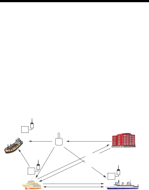
SYSTEM OVERVIEW
System overview
The Automatic Identification System (AIS) was originally developed to aid the Vessel Traffic Services (VTS) by use of a VHF transponder working on Digital Selective Call (DSC) at VHF CH70, and is still in use along the UK coastal areas and others. Some time later the IMO developed a Universal AIS using the new sophisticated technology called Self-Organized Time Division Multiple Access (SOTDMA) based on a VHF Data Link (VDL).
The system operates in three modes – autonomous (continuous operation in all areas), assigned (data transmission interval remotely controlled by authority in traffic monitoring service) and polled (in response to interrogation from a ship or authority). It is synchronized with GPS time to avoid conflict among multiple users (IMO minimum 2000 reports per minute and IEC requires 4500 reports on two channels). The VHF channels 87B and 88B are commonly used and in addition there are local AIS frequencies. Shipborne AIS transponders exchange various data as specified by the IMO and ITU on either frequency automatically set up by the frequency management telecommand received by the DSC receiver on ship.
AIS-fitted AtoN broadcasts its identification, type of operation, location, displacement, etc. at 3-min intervals or at a reporting rate designated by the Administration authorities.
Aids to Navigation
(AtoN)
Transponder
VTS Center transmits TDMA CH management message including code, type, position, etc. of buoys every 3 min, and the AtoN broadcasts these messages for ships. 
VTS center
The VTS center transmits a command on frequency assignment, slots, report rate, VHF output power, channel spacing, etc. (Assigned mode)
Transponder
Transponder
Static and Dynamic information incl. MMSI, Name, POSN, HDG, COG, SOG
Own ship |
Interrogation and Response |
Ship 1 |
All ships broadcast Static and Dynamic information (autonomous and continuous mode). If OS wants to know information about ship 1, OS shall send an interrogation in polling mode; then ship 1 will transmit her response on the same VHF channel without operator intervention.
AIS system
viii
Not all ships carry AIS
The Officer of the Watch (OOW) should always be aware that other ships, and in particular leisure craft, fishing boats and warships, and some coastal shore stations (including Vessel Traffic Service centers) might not be fitted with AIS.
The OOW should also be aware that AIS fitted on other ships as a mandatory carriage requirement might be switched off by the master if its use might compromise the security of the vessel. Thus, users are therefore cautioned to always bear in mind that information provided by AIS may not be giving a complete or correct “picture” of shipping traffic in their vicinity.
Use of AIS in collision avoidance
As an anti-collision aid, the AIS has the following advantages over radar:
•Information provided in near real-time
•Capable of instant presentation of target course alterations
•Not subject to target swap
•Not subject to target loss in clutter
•Not subject to target loss due to abrupt maneuvers
•Able to "detect" ships within VHF/FM coverage, including in some circumstances, around bends and behind islands.
When using the AIS for anti-collision purposes it is important to remember that the AIS is an additional source of navigation information. It does not replace other navigational systems. The AIS may not be giving a complete or correct “picture” of shipping traffic in its vicinity.
The use of the AIS does not negate the responsibility of the OOW to comply with all collision regulation requirements, especially the maintaining of a proper look-out. The prudent navigator uses all aids available to navigate the ship.
Erroneous information
Erroneous information implies a risk to other ships as well as your own. Poorly configured or improperly calibrated sensors might lead to incorrect information being transmitted. It is the user’s responsibility to ensure that all information entered into the system is correct and up to date.
ix
This page intentionally left blank.
x
1.OPERATION
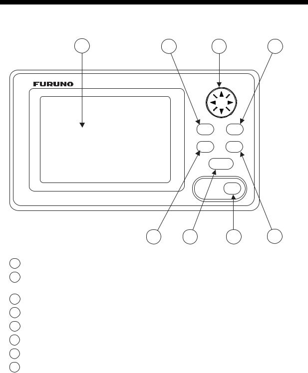
1.1Description of Controls
1 |
3 |
2 |
4 |
UNIVERSAL AIS
MENU ENT
DISP DIM
NAV
STATUS
FA-150 PWR
|
|
5 |
7 |
8 |
6 |
1 |
LCD Screen: |
Displays various data. |
|
|
|
2 |
CursorPad: |
Shifts cursor; chooses menu items and options; |
|
||
|
|
selects alphanumeric data. |
|
|
|
3 |
MENU key: |
Opens the menu. |
|
|
|
4 |
ENT key: |
Terminates keyboard input; changes screen. |
|
|
|
5 |
DISP key: |
Chooses a display screen; closes menu. |
|
|
|
6 |
DIM key: |
Adjusts panel dimmer and LCD contrast. |
|
|
|
7 |
NAV STATUS key: |
Displays NAV STATUS menu, which contains voyage-related data. |
|||
8 |
PWR key: |
Turns the power on and off. |
|
|
|
Notice: The nominal viewing distance is 50 cm.
1-1
1. OPERATION
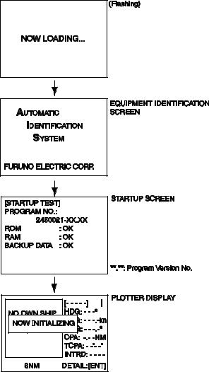
1.2Turning the Power On and Off
Press the PWR key to turn the equipment on or off. When powered, the equipment sounds a beep then proceeds in the sequence shown below.
The startup screen displays the program version number and the results of the ROM, RAM and backup data test, showing OK or “NG” (No Good) as the result. If “NG” appears for any of the check result, try resetting the power to restore normal operation. If that does not work, contact your dealer for advice. After the startup test is completed the plotter display appears, showing the messages “NO OWN SHIP POSITION AVAILABLE.” and “NOW INITIALIZING.” These messages mean that position data has not yet arrived and the transponder is initializing itself, respectively. When both messages disappear, the equipment is ready for use. If the message “ENTER MMSI!” appears, the vessel’s MMSI has not been registered in the equipment. Enter MMSI.
If there is no response from the transponder unit or AIS symbols do not appear, the message “COMMUNICATION ERROR” appears on the screen. Press any key to erase the message. Check if the transponder unit is powered. Also check the connection between the monitor unit and the transponder unit.
1-2
1. OPERATION
The FA-150 should be powered while underway or at anchor. The master may switch off the AIS if he believes that the continual operation of the AIS might compromise the safety or security of his ship. The AIS should be restarted once the source of danger has gone.
The equipment transmits own ship static data within two minutes of start-up and it is transmitted at six-minute intervals thereafter. Static data includes MMSI number, IMO number, call sign, ship name, ship length and width, ship type and GPS antenna position.
In addition to static data, ship’s dynamic data is also transmitted. This data includes position with quality indication, SOG, COG, rate of turn, heading, etc. Dynamic data is transmitted every 2 s to 3 min depending on ship’s speed and course change. Voyage-related data, such as ship’s draft, hazardous cargo, destination and estimated time of arrival, are transmitted at six-minute intervals.
The FA-150 starts receiving data from AIS-equipped ships as soon as it is turned on, and those ships’ location are shown on the plotter display with the AIS symbol. (To learn more about the plotter display, see section 1.7.) With connection of a radar or ECDIS, the AIS target symbols may be overlaid on the radar or ECDIS.
Note 1: If no navigation sensor is installed or a sensor such as a gyrocompass has failed, the AIS automatically transmits “not available” data to AIS-equipped ships.
Note 2: The reporting intervals are as follows:
Ship’s dynamic conditions and nominal reporting interval
Ship’s navigation status |
Nominal reporting interval |
Ship at anchor and not moving faster than 3 kn |
3 minutes |
Ship at anchor and moving faster than 3 kn |
10 seconds |
|
|
Ship speed 0-14 kn |
10 seconds |
Ship speed 0-14 kn and changing course |
3 1/3 seconds |
Ship speed 14-23 kn |
6 seconds |
Ship speed 14-23 kn and changing course |
2 seconds |
Ship speed faster than 23 kn |
2 seconds |
Ship speed faster than 23 kn and changing course |
2 seconds |
1-3

1. OPERATION
1.3Adjusting Panel Dimmer and Contrast
The panel dimmer and display contrast may be adjusted as follows:
1. Press the DIM key to show the dimmer and contrast setting screen.
D I M M E R ( 0 ~8 )
4
C O N T R A S T ( 0 ~6 3 )  44
44
EXIT: [ENT]
2.Use ▲ or ▼ to adjust the panel dimmer; ◄ or ► to adjust the contrast. (The default dimmer and contrast settings are 4 and 45, respectively. To restore default settings see section 3.9 Restoring Default Settings.)
3.Press the ENT key to close the setting screen.
Note: If the equipment is turned off with the contrast setting of 35 or lower, the equipment will start up with the contrast setting 36 when the power is again turned on.
1-4

1. OPERATION
1.4Menu Overview
You can select the functionality of the equipment through the menu. If you get lost in operation, press the MENU key until you return to the main menu. The complete menu tree is provided in the Appendix.
1.4.1Menu operating procedure
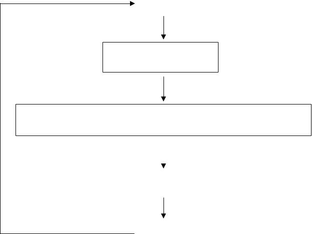
1. Press the MENU key to display the main menu.
[MENU]
MSG
SENSOR STATUS
INTERNAL GPS
USER SETTINGS
INITIAL SETTINGS
CHANNEL SETTINGS
DIAGNOSTICS
2.Press ▲ or ▼ on the CursorPad to select a menu then press the ENT key.
3.Press ▲ or ▼ to select a sub-menu then press the ENT key.
There are two types of sub-menus: option selection and data input. (Some sub-menus combine both.) Below are examples of each type of sub-menu.
[USER SETTINGS]
KEY BEEP |
: |
ON |
|
ALARM BUZZER |
: ON |
||
AUTO SORT |
: ON |
||
DISP SART TEST : ON |
|||
LR MODE |
: AUTO |
||
RECEIVED MSG |
|
|
|
CPA/TCPA ALARM
[DRAUGHT&PERSONS]
DRAUGHT: |
0.0 |
m |
NO. OF PERSONS: |
0 |
|
USER SETTINGS sub-menu |
DRAUGHT&PERSONS input screen |
(Option selection) |
(Data input) |
4.Press ▲ or ▼ to select a menu item then press the ENT key.
5.Depending on the sub-menu selected, select an option or enter alphanumeric data.
1-5

1. OPERATION
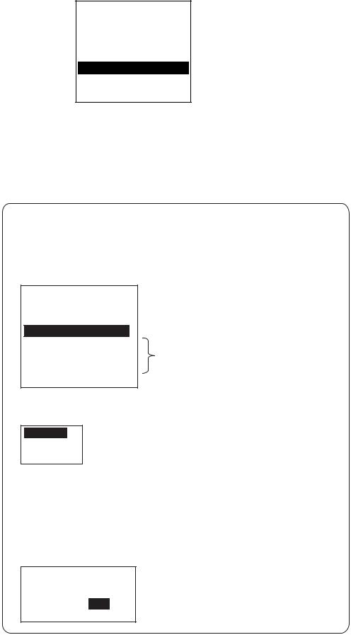
Selecting an option
The example below shows how to select an option from the USER
SETTINGS menu.
a)A window showing the options for the item selected is overlaid on the sub-menu. For example, the options for KEY BEEP are as shown below.
[USER SETTINGS] |
|
|
||||||
KEY BEEP |
: |
ON |
|
|
|
|
|
|
|
|
|
|
|
|
|
|
|
ALARM BUZZER |
: |
|
|
|
|
|
|
|
ON |
|
|
|
Options window |
||||
AUTO SORT |
: |
OFFN |
|
|
|
|||
|
|
|
||||||
|
|
|
|
|||||
DISP SART TEST : |
|
|
|
|
|
|
|
|
ON |
|
|
||||||
|
|
|
|
|||||
LR MODE |
: AUTO |
|
|
|||||
RECEIVED MSG |
|
|
|
|
|
|
|
|
CPA/TCPA ALARM |
|
|
||||||
|
|
|
|
|
|
|
|
|
b) Press ▲ or ▼ to select option desired then press the ENT key.
Entering alphanumeric data
The example below shows how to enter numeric data on the DRAUGHT&PERSONS sub-menu, which is on the NAV STATUS menu.
[DRAUGHT&PERSONS] W |
|
|
|||
DRAUGHT: |
00.0 m |
|
Cursor |
||
|
|
|
|
|
|
NO. OF PERSONS: |
0 |
|
|||
|
|
||||
|
|
|
|
|
|
a)Select DRAUGHT and press the ENT key.
b)Press ▲ or ▼ to select appropriate numeric. Pressing ▲ displays alphanumeric characters cyclically in order of blank space, alphabet, numerals, and symbols.
c)Press ► to shift the cursor to the adjacent place, then use ▲ or ▼ to select alphanumeric character.
d)Repeat steps b) and c) to finish entering data. To erase a character, insert a space.
e)After entering all data, press the ENT key to register input.
6.Press the DISP key to close the menu.
1-6
1. OPERATION
1.5Entering Voyage-Related Data
There are six items on the NAV STATUS menu that you will need to enter at the start of a voyage.
• |
Navigation status |
• |
Cargo type |
• |
Arrival time |
• |
Destination |
• |
No. of persons |
• |
Draught |
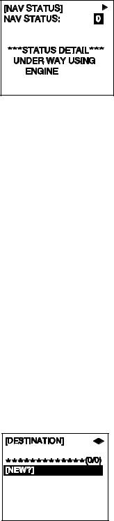
1. Press the NAV STATUS key to open the NAV STATUS menu.
2.If your navigation status is different from that shown, follow the procedure below. If it is the same as shown, go to step 3.
a)Press the ENT key.
b)Press ▲ or ▼ to select appropriate status then press the ENT key. Refer to the data below to select appropriate nav status.
00:UNDER WAY USING ENGINE
01:AT ANCHOR
02:NOT UNDER COMMAND
03:RESTRICTED MANEUVERABILITY
04:CONSTRAINED BY HER DRAUGHT
05:MOORED
06:AGROUND
07:ENGAGED IN FISHING-TRAWLING
08:UNDER WAY SAILING
09:ENGAGED IN FISHING OTHER THAN TRAWLING
10:AIR-CUSHION VESSEL IN NON-DISPLACEMENT MODE OR WIG CRAFT TAKING OFF, LANDING OR IN FLIGHT
11:POWER-DRIVEN VESSEL TOWING ASTERN
12:POWER-DRIVEN VESSEL PUSHING AHEAD OR TOWING ALONGSIDE
13:IN DISTRESS OR REQUIRING ASSISTANCE
14:AIS-SART (ACTIVE), SEEKING TO ATTRACT ATTENTION*
*Input not possible. “ERROR REGIST PRESS ANY KEY” appears.
15:NOT DEFINED (DEFAULT), AIS-SART (TEST)
3.Press ► to show the DESTINATION sub-menu.
1-7
1.OPERATION
4.NEW is selected; press the ENT key.
[DESTINATION] ENTER A NEW
DESTINATION
QUIT:[NAV STATUS]
NAV STATUS menu, DESTINATION sub-menu, destination input
5.Press the ENT key. Enter destination then press the ENT key. You can use up to 20 alphanumeric characters (\, ^, !, ,, $, and * count as three characters), and enter 20 destinations. (For how to enter alphanumeric characters, see “Entering alphanumeric data” on page 1-6.)
PROCESSING DESTINATIONS
If you have already registered some destinations, the DESTINATION sub-menu looks something like the one below. From this screen you can select, edit or delete destinations.
[DESTINATION] WX
COTE D'IVOIRE  Current destination
*************(0/3)
[NEW?]
COTE D'IVOIRE
SAN FRANCISCO Destination list
SEATTLE
1)Select appropriate destination then press the ENT key to show the options window below.
SELECT
EDIT
DELETE
2) Select SELECT, EDIT or DELETE as appropriate then press the ENT key. Do one of the following according to your objective.
SELECT: Select a destination.
EDIT: Press the ENT key twice then edit the destination.
DELETE: The prompt below appears. Press W to select
YES; press the ENT key.
DESTINATION DELETE.
ARE YOU SURE?
YES NO
1-8

1. OPERATION
6. Press ► to show the ARRIVAL TIME sub-menu.
[ARRIVAL TIME]
DATE[UTC]: 25/APR
TIME[UTC]: 0:00
7.DATE[UTC] is selected; press the ENT key.
8.Enter the date of arrival then press the ENT key.
9.TIME[UTC] is selected; press the ENT key.
10.Enter the estimated time of arrival, in 24-hour notation, then press the ENT key.
11.Press ► to show the CARGO TYPE sub-menu.
[CARGO TYPE] |
|
TYPE NO.: |
00 |
**** TYPE DETAIL**** NOT AVAILABLE
12.TYPE NO. is selected; press the ENT key.
13.Select type of vessel/cargo, referring to the table on the next page, then press the ENT key.
Note 1: Only the second digit for the type of vessel is entered here; the first digit is entered on the INITIAL SETTINGS menu, during installation.
Note 2: When “Tanker” is selected and the Nav status is “Moored”, output power is automatically switched to 1 W when SOG is less than 3 knots. Further, in the above condition, when SOG becomes higher than 3 knots, the pop-up message “CHANGE NAV STATUS?” appears and a beep sounds. (The pop-up message “TX POWER CHANGED” also appears to notify you that the Tx power has changed). To erase the pop-up message, press any key or lower SOG below 3 knots.
1-9
1. OPERATION
10 |
FUTURE USE ALL SHIPS OF THIS TYPE |
60 |
PASSENGER SHIPS |
ALL SHIPS OF THIS TYPE |
||
11 |
FUTURE USE CARRYING DG, HS, OR MP( ) |
61 |
PASSENGER SHIPS |
CARRYING DG, HS, OR MP(X) |
||
12 |
FUTURE USE CARRYING DG, HS, OR MP(Y) |
62 |
PASSENGER SHIPS |
CARRYING DG, HS, OR MP(Y) |
||
13 |
FUTURE USE CARRYING DG, HS, OR MP(Z) |
63 |
PASSENGER SHIPS |
CARRYING DG, HS, OR MP(Z) |
||
14 |
FUTURE USE CARRYING DG, HS, OR MP(OS) |
64 |
PASSENGER SHIPS |
CARRYING DG, HS, OR MP(OS) |
||
15 |
FUTURE USE FUTURE USE |
65 |
PASSENGER SHIPS |
FUTURE USE |
||
16 |
FUTURE USE FUTURE USE |
66 |
PASSENGER SHIPS |
FUTURE USE |
||
17 |
FUTURE USE FUTURE USE |
67 |
PASSENGER SHIPS |
FUTURE USE |
||
18 |
FUTURE USE FUTURE USE |
68 |
PASSENGER SHIPS |
FUTURE USE |
||
19 |
FUTURE USE NONE |
69 |
PASSENGER SHIPS |
NONE |
||
20 |
WIG |
ALL SHIPS OF THIS TYPE |
70 |
CARGO SHIPS |
ALL SHIPS OF THIS TYPE |
|
21 |
WIG |
CARRYING DG, HS, OR MP(X) |
71 |
CARGO SHIPS |
CARRYING DG, HS, OR MP(X) |
|
22 |
WIG |
CARRYING DG, HS, OR MP(Y) |
72 |
CARGO SHIPS |
CARRYING DG, HS, OR MP(Y) |
|
23 |
WIG |
CARRYING DG, HS, OR MP(Z) |
73 |
CARGO SHIPS |
CARRYING DG, HS, OR MP(Z) |
|
24 |
WIG |
CARRYING DG, HS, OR MP(OS) |
74 |
CARGO SHIPS |
CARRYING DG, HS, OR MP(OS) |
|
25 |
WIG |
FUTURE USE |
75 |
CARGO SHIPS |
FUTURE USE |
|
26 |
WIG |
FUTURE USE |
76 |
CARGO SHIPS |
FUTURE USE |
|
27 |
WIG |
FUTURE USE |
77 |
CARGO SHIPS |
FUTURE USE |
|
28 |
WIG |
FUTURE USE |
78 |
CARGO SHIPS |
FUTURE USE |
|
29 |
WIG |
NONE |
79 |
CARGO SHIPS |
NONE |
|
30 |
FISHING |
|
80 |
TANKER |
ALL SHIPS OF THIS TYPE |
|
31 |
TOWING |
|
81 |
TANKER |
CARRYING DG, HS, OR MP(X) |
|
32 |
LENGTH OF THE TOW EXCEEDS 200M OR BREADTH EXCEEDS 25M |
82 |
TANKER |
CARRYING DG, HS, OR MP(Y) |
||
33 |
ENGAGED IN DREDGING OR UNDERWATER OPERATIONS |
83 |
TANKER |
CARRYING DG, HS, OR MP(Z) |
||
34 |
ENGAGED IN DIVING OPERATIONS |
84 |
TANKER |
CARRYING DG, HS, OR MP(OS) |
||
35 |
ENGAGED IN MILITARY OPERATIONS |
85 |
TANKER |
FUTURE USE |
||
36 |
SAILING |
|
86 |
TANKER |
FUTURE USE |
|
37 |
PLEASURE CRAFT |
87 |
TANKER |
FUTURE USE |
||
38 |
FUTURE USE |
|
88 |
TANKER |
FUTURE USE |
|
39 |
FUTURE USE |
|
89 |
TANKER |
NONE |
|
40 |
HSC |
ALL SHIPS OF THIS TYPE |
90 |
OTHER TYPE OF SHIP ALL SHIPS OF THIS TYPE |
||
41 |
HSC |
CARRYING DG, HS, OR MP(X) |
91 |
OTHER TYPE OF SHIP CARRYING DG, HS, OR MP(X) |
||
42 |
HSC |
CARRYING DG, HS, OR MP(Y) |
92 |
OTHER TYPE OF SHIP CARRYING DG, HS, OR MP(Y) |
||
43 |
HSC |
CARRYING DG, HS, OR MP(Z) |
93 |
OTHER TYPE OF SHIP CARRYING DG, HS, OR MP(Z) |
||
44 |
HSC |
CARRYING DG, HS, OR MP(OS) |
94 |
OTHER TYPE OF SHIP CARRYING DG, HS, OR MP(OS) |
||
45 |
HSC |
FUTURE USE |
95 |
OTHER TYPE OF SHIP FUTURE USE |
||
46 |
HSC |
FUTURE USE |
96 |
OTHER TYPE OF SHIP FUTURE USE |
||
47 |
HSC |
FUTURE USE |
97 |
OTHER TYPE OF SHIP FUTURE USE |
||
48 |
HSC |
FUTURE USE |
98 |
OTHER TYPE OF SHIP FUTURE USE |
||
49 |
HSC |
NONE |
99 |
OTHER TYPE OF SHIP NONE |
||
50 |
PILOT |
|
WIG: Wing in ground |
|
||
51 |
SEARCH AND RESCUE VESSELS |
|
||||
52 |
TUGS |
|
HSC: High speed craft |
|||
53 |
PORT TENDERS |
DG: |
Dangerous goods |
|||
54 |
VESSELS WITH ANTI-POLL UTION FACILITIES OR EQUIPMENT |
HS: |
Harmful substances |
|||
55 |
LAW ENFORCEMENT VESSELS |
MP: |
Marine pollutants |
|||
56 |
SPARE-FOR ASSIGNMENTS TO LOCAL VESSELS |
0-9: |
Undefined |
|
||
57SPARE-FOR ASSIGNMENTS TO LOCAL VESSELS
58MEDICAL TRANSPORTS
59SHIPS ACCORDING TO RESOLUTION NO 18
14.Press ► to display the DRAUGHT&PERSONS sub-menu.
15.DRAUGHT is selected; press the ENT key.
16.Enter ship’s draught (setting range: 0-25.5(m)) then press the ENT key.
17.NO. OF PERSONS is selected; press the ENT key.
18.Enter total number of persons onboard (setting range: 0-8191) then press the ENT key. Enter 8191 for total greater than 8190.
19.Press the DISP key to close the menu.
[DRAUGHT&PERSONS]
DRAUGHT: |
0.0 |
m |
NO. OF PERSONS: |
0 |
|
1-10

1. OPERATION
1.6Setting CPA/TCPA
Set the CPA (Closest Point of Approach) and TCPA (Time to Closest Point of Approach) range for which you want to be alerted to AIS targets which can be on a collision course. When a ship’s CPA and TCPA are lower than that set here, the buzzer sounds (if active) and the message COLLISION ALARM appears.
1.Press the MENU key to open the main menu.
2.Select USER SETTINGS then press the ENT key.
3.Select CPA/TCPA ALARM then press the ENT key.
[CPA/TCPA ALARM]
CPA |
: |
6.00 |
NM |
TCPA |
: 60 min |
||
ALARM MODE |
: ON |
||
ALARM BUZZER : ON
QUIT[MENU]
4.CPA is selected; press the ENT key.
5.Enter CPA (setting range: 0-6.00 NM) then press the ENT key.
6.TCPA is selected; press the ENT key.
7.Enter TCPA (setting range: 0-60 min) then press the ENT key.
8.ALARM MODE is selected; press the ENT key.
9.Select ON to activate the CPA/TCPA alarm; OFF to deactivate it. Press the ENT key.
10.ALARM BUZZER is selected; press the ENT key.
11.Select ON to enable the CPA/TCPA audio alarm, or OFF to disable it. Press the ENT key.
12.Press the DISP key to close the menu.
1-11
1. OPERATION
1.7Selecting a Display
Use the DISP key to select a display. Each time the key is pressed, the display changes in the sequence shown below.
PLOTTER |
PLOTTER DISPLAY |
|
(See section 1.7.1.) |
||
DISPLAY |
||
|
||
|
|
TARGET LIST |
|
|
|
|
|
DANGEROUS |
|
(See section 1.7.2. ) |
TARGET LIST |
|
|
|
|
LIST |
|
|
|
|
|
|
|
|
|
Switch between these displays with , .
DANGEROUS (TARGET) LIST (See section 1.7.3.)
When a dangerous target exists, the dangerous target list has priority.
OWN STATIC |
|
|
OWN STATIC |
|
OWN STATIC |
|
OWN STATIC |
|
OWN STATIC |
|
DATA 1 |
|
|
DATA 2 |
|
DATA 3 |
|
DATA 4 |
|
DATA 5 |
|
|
|
|
|
|
|
|
|
|
|
|
OWN SHIP'S STATIC DATA |
|
|
|
|
|
|
|
|||
|
|
|
|
|
|
|
||||
Switch among these |
|
|
|
|
|
|
|
|
||
displays with |
. |
|
|
|
|
|
|
|
||
(See section 1.7.4.) |
|
|
|
|
OWN SHIP'S DYNAMIC DATA |
|||||
|
|
|
|
|||||||
|
|
|
|
|
|
|
||||
|
|
|
|
|
OWN DYNAMIC |
|||||
|
|
|
|
|
DATA |
(See section 1.7.5.) |
|
|||
|
|
|
|
|
|
|
|
|
||
|
|
|
|
|
|
|
|
|
|
|
ALARM |
ALARM STATUS DISPLAY |
|
(See section 3.5.) |
||
STATUS |
||
|
||
|
|
1-12
1. OPERATION
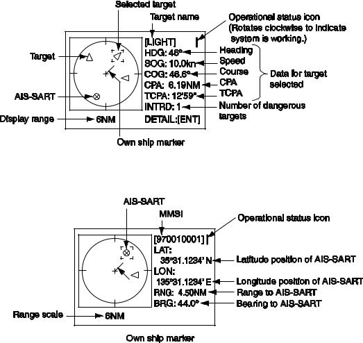
1.7.1Plotter display
The plotter display, which automatically appears after the power-on sequence, shows the name, heading, SOG, COG, CPA and TCPA of AIS-equipped ships, AIS-SARTs, etc. within the range selected. The number of dangerous targets is also indicated.
Data for ship target
A target marker (hollow triangle) indicates the presence of a vessel equipped with AIS in a certain location and course. To find detailed information about a vessel, see section 1.7.2.
If two or more targets occupy a similar position, the display priority order is selected target, AIS-SART and ship target.
Data for AIS-SART
1-13
1. OPERATION
Operations on the plotter display
1.Press the DISP key to show the plotter display.
2.Use ▼ or ▲ to select the range. The available ranges are (in nm) 0.125, 0.25, 0.5, 0.75, 1.5, 3, 6, 12, and 24.
3.To find a target’s data, see section 1.7.2.
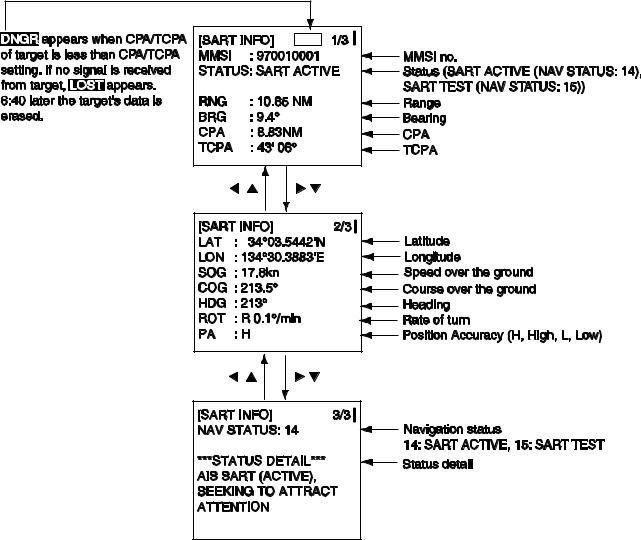
Note 1: A target is declared a lost target under the conditions shown in the table below. A target is erased from the screen 6 minutes and 40 seconds after it is declared a lost target.
Ship’s navigation status |
Target declared as |
|
lost target after; |
Class A |
|
Ship at anchor or moored and not moving faster than 3 kn |
10 minutes |
Ship at anchor or moored and moving at more than 3 kn |
50 seconds |
0-14 kn speed |
50 seconds |
0-14 kn speed with course change |
50 seconds |
14-23 kn speed |
30 seconds |
14-23 kn speed with course change |
30 seconds |
Speed higher than 23 kn |
10 seconds |
Speed higher than 23 kn with course change |
10 seconds |
Class B |
|
Speed over ground less than 2 kn |
10 minutes |
Speed over ground 2 kn or higher |
150 seconds |
Note 2: When a target’s CPA and TCPA are lower than set in section 1.6, the audio alarm sounds (if active). Press any key to silence the audio alarm. Take suitable measures to avoid collision.
Note 3: "DNGR" (DANGER) appears at the end of the HDG line when a target's CPA and TCPA are lower than the CPA and TCPA alarm settings. Further, when a target becomes a lost target, “LOST” appears at the end of the HDG line.
1-14
1. OPERATION
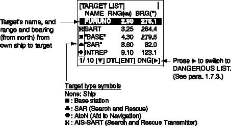
1.7.2Target list (displaying target data)
1.At the plotter display, press the DISP key to show the TARGET LIST, which lists all AIS targets and AIS-SARTs being detected by the FA-150.
Note 1: The dangerous target list appears when there are dangerous targets. You can switch to the target list by pressing ◄.
Note 2: If there is no data for the target selected, the message NO SEL appears. Hit any key to escape.
Note 3: Targets are automatically sorted in range order (closest to furthest) when no key is operated for 30 seconds. Target order is then updated every five seconds.
Note 4: When AUTO SORT on the USER SETTINGS menu is OFF, the range and bearing to a target are updated. However, target order is not updated. To do this, press ◄, and targets are sorted in range order. “NOW SORTING” is shown while sorting.
Note 5: To select a target on the plotter display, press ◄ or ► to select the target then press the ENT key. Press ► to select from nearest to furthest; ◄ to select from furthest to nearest. The display then looks something like the one shown at the top of the next page. If you wish to see other target data, go to step 3 below.
Note 6: The information source is specified from obtained MMSI and ship's name of an AIS target.
2.Use ▼ or ▲ to select the target whose data you wish to view then press the ENT key. The display then looks something like one of the displays shown on the next several pages, according to type of target.
3.Use ▼ or ▲ to scroll the display to see other data.
1-15
1. OPERATION
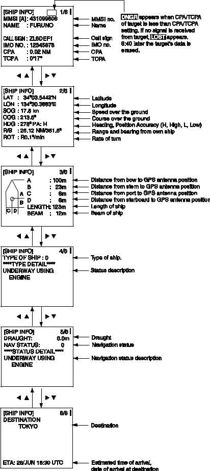
Ship info display, mobile class A
1-16
1. OPERATION
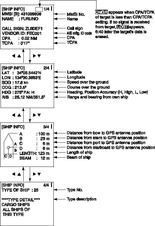
Ship info display, mobile class B
1-17
1. OPERATION
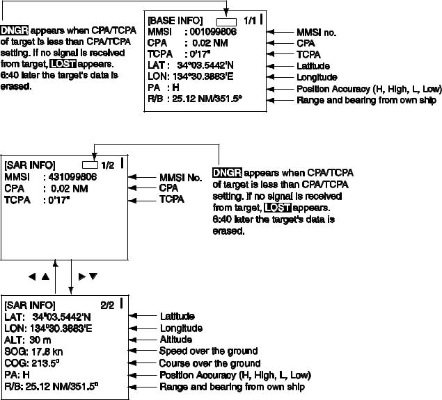
Base station display
SAR (Search and Rescue) info display
1-18
1. OPERATION
AIS-SART info display
1-19
Loading...