


Furuno 526TID-LTD-12, 526TID-LTD-20, 556TID-LTD-12, 556TID-LTD-20, SS264N-200-20 Installation Instructions

OWNER’S GUIDE & INSTALLATION INSTRUCTIONS
17-458-01 rev. 07 01/12/13
Thru-Hull, 1kW
Tilted Element™ Transducer
Tilt Angles: 0°, 12°, 20°
Models: B164, B175H/M/L, SS164, SS175H/M/L
Pairs: B264N, B264W, SS264N, SS264W
U.S. Patent No. 7,369,458. UK Patent No. 2 414 077. U.S. Patent Pending
Follow the precautions below for optimal product performance and to reduce the risk of property damage, personal injury, and/or death.
WARNING: Always install the two set screws with marine sealant applied to the threads. This will hold the hull nut firmly in place. Failure to do so may allow the hull nut to become loose.
WARNING: Always wear safety goggles and a dust mask when installing.
WARNING: Immediately check for leaks when the boat is placed in the water. Do not leave the boat unchecked for more than three hours. Even a small leak may allow considerable water to accumulate.
WARNING: Stainless steel housing in a metal hull—
Be sure the washer contacts the hull. Do not tighten the hull nut with the washer against the isolation bushing, as the housing will not be firmly installed. If necessary, sand the isolation bushing until the washer rests against the hull.
CAUTION: CHIRP transducer—Do not install in the engine compartment or other hot place. The transducer may fail if it overheats.
CAUTION: CHIRP transducer—Always operate the transducer in water. Operating in air will allow the transducer to overheat resulting in failure.
CAUTION: The arrow on the top of the transducer must point toward the keel or centerline of the boat. This will align the angle of the element inside the transducer with the deadrise angle of your hull.
CAUTION: Never install a metal transducer on a vessel with a positive ground system.
CAUTION: Never pull, carry, or hold the transducer by its cable; this may sever internal connections.
CAUTION: Stainless steel housing in a metal hull—
Stainless steel housing must be isolated from a metal hull to prevent electrolytic corrosion. Use the isolation bushing supplied.
CAUTION: Never use solvents. Cleaners, fuel, sealants, paint, and other products may contain solvents that can damage plastic parts, especially the transducer’s face.
IMPORTANT: For optimal performance, apply marine sealant to the entire inside surface of the spacer. This will fill the gap between the spacer and the sidewall of the transducer preventing vibration.
IMPORTANT: Read the instructions completely before proceeding with the installation. These instructions supersede any other instructions in your instrument manual if they differ.
Record the information found on the cable tag for future reference.
Part No._________________Date___________Frequency________kHz
Applications
•Bronze housing recommended for fiberglass or wood hulls.
Never install a bronze housing in an aluminum hull, because electrolytic corrosion will occur.
•Stainless steel housing compatible with all hull materials. Recommended for metal hulls to prevent electrolytic corrosion provided the stainless steel housing is isolated from the metal hull.
Match Tilt Angle of Transducer to Deadrise
Be sure your transducer model matches the deadrise angle of your hull at the selected mounting location. The tilt angle is printed on the top of the transducer (see Figure 1). To measure the deadrise angle of your hull at the selected mounting location, use an angle finder or a digital level (see Figure 2).
•0° transducer for deadrise angles from 0° to 7°
•12° transducer for deadrise angles from 8° to 15°
•20° transducer for deadrise angles from 16° to 24°
tilt angle
B175H
130 - 210 kHz
Figure 1. Top of transducer (0° model shown)
Copyright © 2008 - 2012 Airmar Technology Corp.
transom view |
|
|
|
|
|
|
slope of hull |
|
|
|
|
|
|
|
|
|
deadrise angle |
|
|
|
|
|
|
|
|
|
|
|
|
|
|
|
|
parallel to waterline |
|
Figure 2. Deadrise angle of the hull
Copyright © 2005 Airmar Technology Corp.
Tools & Materials
Safety goggles Dust mask Angle finder
Electric drill with 10mm (3/8") or larger chuck capacity
Drill bit: |
3mm or 1/8" |
Hole saw: |
95mm or 3-3/4" (fiberglass or wood hull) |
|
105 mm or 4" (metal hull) |
Grinder (some installations) Sandpaper
Mild household detergent or weak solvent (such as alcohol) File (installation in a metal hull)
Marine sealant (suitable for below waterline)
Allen wrench: |
3/16" |
Slip-joint pliers |
|
Grommet(s) (some installations) Cable ties
Water-based anti-fouling paint (mandatory in salt water) Installation in a cored fiberglass hull (see page 4):
Hole saw for hull interior: 115mm or 4-1/2" Fiberglass cloth and resin
or Cylinder, wax, tape, and casting epoxy
the noise level, the higher the echosounder gain setting that can be used.
•Choose an accessible spot inside the vessel with a minimum of 178 mm (7") of headroom for the height of the housing, installing the spacer, and tightening the nut and set screws.
•CHIRP transducer—Mount in a cool well-ventilated area away from the engine to avoid overheating.
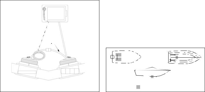
•Pairs—Mount the transducers across from one another on opposite sides of the centerline (keel) (see Figure 3).
Hull Types (see Figure 4)
Planing hull powerboats—Mount well aft, near the centerline, and well inboard of the first set of lifting strakes to ensure that the transducer will be in contact with the water at high speeds. The starboard side of the hull where the propeller blades are moving downward is preferred.
•Outboard and I/O—Mount just forward of the engine(s).
•Inboard—Mount well ahead of the propeller(s) and shaft(s).
•Stepped hull—Mount just ahead of the first step.
•Boat capable of speeds above 25kn (29MPH)—Review the installation location and operating results of similar boats before proceeding.
Mounting Location
CAUTION: Do not mount in line with or near water intake or discharge openings, or behind strakes, fittings, or hull irregularities that will disturb the water flow.
CAUTION: Do not mount in line with trailer rollers or bunks that may damage the transducer’s face.
•The water flowing under the hull must be smooth with a minimum of bubbles and turbulence (especially at high speeds).
•The transducer must be continuously immersed in water.
•The transducer beam must be unobstructed by the keel or propeller shaft(s).
•Choose a location away from interference caused by power and radiation sources such as: the propeller(s) and shaft(s), other machinery, other echosounders, and other cables. The lower
pigtail 
200kHz |
50kHz |
Figure 3. Connecting a Pair—single transmission line
Copyright © 2008 Airmar Technology Corp.
2
Installation
Hole Drilling & Dry Fitting
Cored fiberglass hull—Follow separate instructions on page 4.
1.From inside the hull, using the hull nut as a guide to ensure ample space, mark the center point. Then drill a 3mm or 1/8" pilot hole. If there is a rib, strut, or other hull irregularity near the selected mounting location, drill from the outside.
2.Using a 95mm or 3-3/4" hole saw, cut a hole from outside of the hull perpendicular to the hull surface. It may be necessary to enlarge the hole slightly using a grinder or file.
Stainless steel housing in a metal hull—Use a 105 mm or 4" hole saw to accommodate the isolation bushing. It may be necessary to enlarge the hole slightly using a grinder or file.
3.Sand and clean the area around the hole, inside and outside, to ensure that the sealant will adhere properly to the hull. If there is any petroleum residue inside the hull, remove it with either mild household detergent or a weak solvent (alcohol) before sanding. Metal hull—Remove all burrs with a file and sandpaper.
4.Dry fit the transducer to determine if the spacer must be cut. From outside the hull, push the housing through the mounting hole (see Figure 5). From inside, slide one of the washers onto the housing. Slide the spacer onto the housing with the open end facing the hull. Add the remaining washer. Be sure a minimum of THREE threads are showing on the housing above the washer. If not, cut the spacer to make it shorter. When cutting the spacer, be sure to cut the open end (see Figure 6).
outboard and I/O |
inboard |
|
stepped hull |
Figure 4. |
Best location for the transducer |
Copyright © 2007 - 2011 Airmar Technology Corp. |
|
 Loading...