


 Loading...
Radio Rack Console
RC-1500-1T
There are two versions of the radio rack console: standard type and the dual Inmarsat C type which has two Inmarsat C systems.
For the dual Inmarsat C type, skip the chapter on NBDP.

9-52 Ashihara-cho,
Nishinomiya, Japan
Telephone : 0798-65-2111
Telefax : 0798-65-4200
All rights reserved. |
Printed in Japan |
PUB.No. OME-55970
( TENI ) RC-1500-1T
Your Local Agent/Dealer
FIRST EDITION : JAN. 1995
H : APR. 16,2002
*00080625900*
*00080625900*
* 0 0 0 8 0 6 2 5 9 0 0 *
*OME55970H00*
*OME55970H00*
* O M E 5 5 9 7 0 H 0 0 *
 SAFETY INSTRUCTIONS
"DANGER", "WARNING" and "CAUTION" notices appear throughout this manual. It is the responsibility of the operator of the equipment to read, understand and follow these notices. If you have any questions regarding these safety instructions, please contact a
FURUNO agent or dealer.
This notice indicates a potentially
hazardous situation which, if not DANGER avoided, will result in death or
serious injury.
This notice indicates a potentially
hazardous situation which, if not WARNING avoided, could result in death or
serious injury.
This notice indicates a potentially
hazardous situation which, if not CAUTION avoided, could result in minor or
moderate injury, or property damage.
i
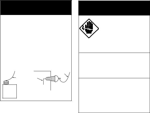

 DANGER
Never touch the SSB antenna, antenna coupler or lead-in insulator when the SSB radiotelephone is transmitting.
High voltage which can cause death is present at the above-mentioned locations when the SSB radiotelephone is transmitting.
Turn off the power before performing maintenance on the SSB antenna.
|
Antenna |
Indoor |
Wire |
Antenna Wire |
|
(High Voltage) |
|
|
Lead-in |
Antenna |
Insulator |
|
|
Coupler |
|

 WARNING
Do not open the equipment.
This equipment uses high voltage electricity which can shock, burn or cause serious injury. Only qualified personnel should work inside the equipment.
Do not disassemble or modify the equipment.
Fire, electrical shock or serious injury can result.
Turn off the power immediately if water leaks into the equipment or the equipment is emitting smoke or fire.
Continued use of the equipment can cause fire or electrical shock.
ii
TABLE OF CONTENTS
Part 1 RC-1500-1T |
|
|
Part 2 |
SSB Radiotelephone |
|
Part 3 |
MF/HF DSC |
|
Part 4 |
NBDP |
Note: NBDP is not included in the dual Inmarsat C type radio |
|
|
rack console. |
Part 5 |
Inmarsat C |
|
SPECIFICATIONS |
|
|
iii
This page is intentionally left blank.

RC-11500-1T
Part
TABLE OF CONTENTS
Chapter 1 INTRODUCTION
1.1 |
System Diagram ............................................................................................................. |
1-1 |
1.2 |
Equipment Description ................................................................................................... |
1-3 |
1.3 |
Mutual Operation of Equipment ..................................................................................... |
1-4 |
1.4 |
Power On/Off .................................................................................................................. |
1-5 |
Chapter 2 RC-1500-1T Control Panel and PP-510
2.1 RC-1500-1T Control Panel ............................................................................................. |
2-1 |
|
2.2 |
Maintenance .................................................................................................................... |
2-4 |
2.3 |
PP-510 ............................................................................................................................ |
2-5 |
Chapter 1 INTRODUCTION
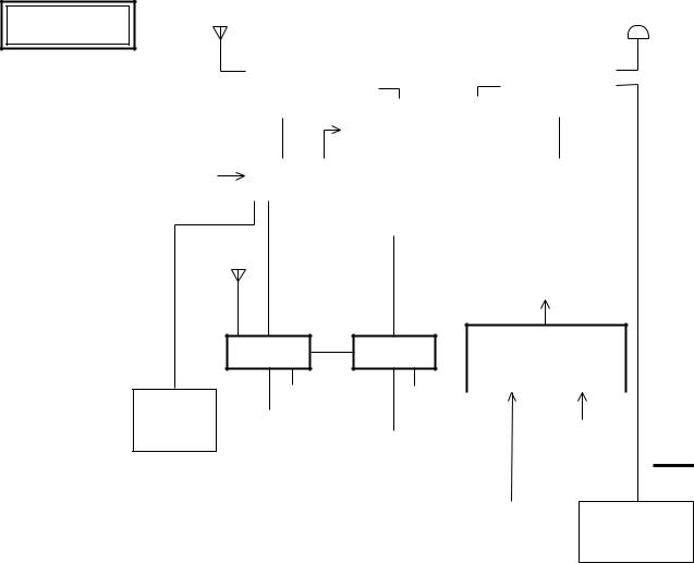
1.1 System Diagram
The figure below shows the system diagram for the RC-1500-1T. Equipment are controlled using FURUNO’s own radio interface system called MIF (see note below).
The type and number of the component differ from set to set.
Note: MIF is a handshaking type signal exchange system developed by FURUNO for remote control of our radio equipment. In the RC-1500-1T, for example, the DSC-60 can automatically set the frequency on the FURUNO SSB Radiotelephone.
RC-1500-1T
|
SSB |
|
|
|
Inmarsat C |
||
|
Radiotelephone |
|
|
|
|||
|
|
|
|
24VDC 24VDC |
|
||
|
|
NMEA OUT |
|
||||
|
|
(Maximum five Outputs) |
|
||||
|
|
|
|
|
|
|
|
NMEA IN |
Distribution |
|
|
|
|
PP-510 |
|
|
|
|
|
||||
(Nav data) |
PCB |
|
|
|
|
|
|
|
|
24VDC |
(Printer) |
||||
|
|
|
|
|
|||
|
|
(Inside Console) |
|
||||
|
|
|
|
|
|
|
|
24VDC (To each unit)
AC/DC
DSC-60 NBDP Changeover Unit
(Radio Switch Box)
|
|
|
PP-510 |
|
Printer |
|
24VDC |
24VDC |
|
|
|
|
24VDC |
|
|
Interface |
|
|
24VDC |
100VAC |
|||||
(Printer) |
|
(IF-8500R) |
|
|
(Reverse |
|||||||
|
|
|
|
(Inside Console) |
||||||||
|
|
|
|
|
|
Source) |
(Main Source) |
|||||
|
|
|
|
|
|
|
|
|||||
|
|
|
|
|
|
|
|
|
|
|
|
|
|
|
|
|
|
|
|
|
|
|
|
|
|
Radio |
IC-302 |
Battery |
(Option) |
|
|
(Distress Alert Unit)
System 1 Standard type
1 – 1
SSB |
|
|
|
|
Radiotelephone |
|
|
|
|
24VDC |
Inmarsat C |
PP-510 |
Inmarsat C |
|
NMEA OUT |
||||
|
(Printer) |
|
||
(Maximum |
|
|
||
five Outputs) |
|
|
|
|
|
|
|
Distribution |
|
|
|
|
|
|
|
|
|
|
|
24VDC |
|
|
|
||||
NMEA IN |
|
|
|
|
|
|
|
|
|
|
24VDC |
|
24VDC |
||||||||||
|
PCB |
|
|
DSC-60 |
|
|
|
|
|
|
|
|
|
|
|
||||||||
(Nav data) |
|
|
|
|
|
|
|
|
|
|
|
|
|
|
|
|
|
|
|
|
|
||
|
|
|
|
|
|
(Inside |
|
|
|
|
|
|
|
|
|
|
|
|
|
|
|
|
|
|
|
|
|
|
|
Console) |
|
|
|
|
|
|
|
|
|
|
|||||||
|
|
|
|
|
|
|
|
|
|
24VDC |
|
|
|
|
|
|
|
|
|
|
|||
|
|
|
|
|
|
|
|
|
|
|
|
|
|
|
|
|
|
|
|
|
|
|
|
|
|
|
|
|
Printer |
|
|
|
|
|
|
|
|
|
|
|
|
|
|
|
|
|
|
|
|
|
|
|
Interface |
|
|
|
|
|
|
|
|
|
|
|
|
|
|
|
|
|
|
|
|
PP-510 |
|
|
|
|
|
|
|
|
|
|
|
|
|
|
|
|
|
|
|||
|
|
|
|
(IF-8500R) |
(Inside Console) |
|
|
|
|
|
|
|
|
|
|
||||||||
|
|
|
|
|
|
|
|
|
|
|
|
|
|
||||||||||
|
|
|
|
|
|
|
|
|
|
|
|
|
|
|
|
|
|||||||
|
|
|
|
|
|
|
|
|
|
|
|
|
|
|
|
|
|||||||
|
|
(Printer) |
|
|
|
|
|
|
|
|
24VDC (To each unit) |
|
|
|
|||||||||
|
|
|
|
|
24VDC |
|
|
|
|
|
|
|
|
|
|
|
|
|
|
|
|
|
|
24VDC |
|
|
|
|
|
|
|
|
|
|
|
|
|
|
|
|
|
|
|
||||
|
|
|
|
|
|
|
|
AC/DC |
|
|
|
|
|
|
|
|
|
|
|||||
|
|
|
|
|
|
|
|
|
|
|
|
|
|
|
|
|
|
|
|
|
|||
|
|
|
|
|
|
|
|
|
|
|
Changeover Unit |
|
|
|
|
|
|||||||
|
|
|
|
|
|
|
|
|
|
|
(Radio Switch Box) |
|
|
|
|
|
|||||||
|
|
|
|
|
|
|
|
|
|
|
|
|
|
|
|
|
|
|
|||||
|
|
|
|
|
|
|
|
|
24VDC |
|
100VAC |
|
|
|
|||||||||
|
|
|
|
|
|
|
(Reverse Source) |
(Main Source) |
|
|
|
||||||||||||
|
|
|
|
|
|
|
|
|
|
|
|
|
|
|
|
|
|
|
|
|
|
|
|
|
|
|
|
|
|
|
|
|
|
|
|
|
|
|
|
|
|
|
|
|
|
|
|
|
|
|
|
|
|
|
|
|
|
|
Radio |
|
|
|
IC-302 |
|
|
IC-302 |
|||||
|
|
|
|
|
|
|
|
|
|
|
Battery |
|
|
(Option) |
|
|
(Option) |
||||||
|
|
|
|
|
|
|
|
|
|
|
|
|
|
|
|
|
|
|
|
|
|
|
|
|
|
|
|
|
|
|
|
|
|
|
|
|
|
|
|
(Distress Alert Unit) |
(Distress Alert Unit) |
||||||
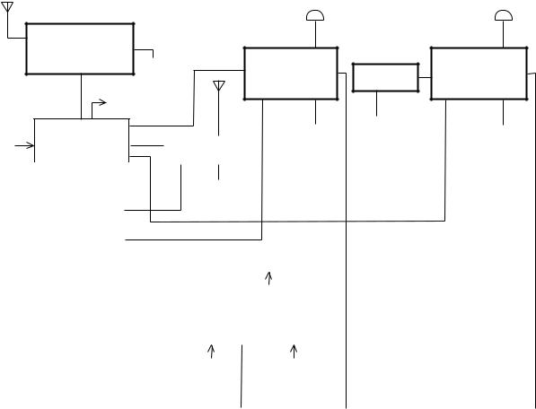
System 2 Dual Inmarsat C type
1 – 2
1.2 Equipment Description
Keep the all equipment powered while the vessel is underway by regulations.
FURUNO SSB Radiotelephone
For ship-ship and ship-station radio communications in the MF/HF band. The main communications modes used are;
•Voice communications (J3E/H3E) via the handset
•DSC communications (Telex) by the DSC-60
•Telex communications by the DP-6
DSC-60 MF/HF DSC Terminal
The DSC-60 has many functions. Below are its main functions.
•Distress alert: Transmit the distress alert via the FURUNO SSB Radiotelephone.
•Watches DSC distress and safety frequencies. The DSC-60 receives distress alert from vessel in distress and all ships call (safety and urgent call) from ship or coast station.
•All Ships Call: For urgent situation on own ship (for example, request for medical assistance).
•Individual Call: Place a call to a specific ship or coast station.
NBDP Terminal
The DP-6 provides Telex communications with coast stations over the MF/HF band via the FURUNO SSB Radiotelephone. Furthermore, it can receive MSI (Maritime Safety Information) messages via the FURUNO SSB Radiotelephone (Scan reception).
Note: NBDP is not included in the dual Inmarsat C type radio rack console.
Inmarsat C Mobile Earth Station
Provides distress and general Telex communications for mobile and fixed terrestrial subscribers in the Inmarsat C communications network. Telex messages are processed by what is known as store-and-forward Telex. A Telex message transmitted by you arrives at a coast station where it is stored temporarily and then delivered to the subscriber specified (No full duplex communications possible.)
AC/DC Radio Switch Box
The AC/DC Radio Switch Box consists of a battery charger and two rectifiers (PR-850AR and PR-300) which can accept both AC and DC powers. In the event of main AC power failure, auxiliary power (battery) provides power to the equipment, for the amount of time stipulated by radio regulations.
1 – 3
1.3 Mutual Operation of Equipment
As noted earlier, the equipment in this radio console are interfaced by FURUNO's MIF radio interface. For example, to transmit a message over the DSC-60 or DP-6, the Tx and Rx frequencies and class of emission are automatically set on the FURUNO SSB Radiotelephone and then the message is transmitted.
Two printers are supplied and one is dedicated to the Inmarsat C. The other printer is for both the DSC-60 and DP-6. If the DP-6 is used (message transmission or reception), this printer is automatically connected to the DP-6 to print out the data. When the printer selector switch in the console is set to the “AUTO” position, it automatically connects one of those equipment to the printer on a first-come-first-served basis. For example, if the DSC-60 is used (message transmission or reception), the printer selector switch automatically connects the printer to the DSC-60 and disconnects itself from other equipment.
Connection between DSC-60 and DP-6
Suppose you transmitted a call over the DSC-60 and want to communicate with the receiving station by the DP-6 instead of FURUNO SSB Radiotelephone. If the DSC-60 and DP-6 were not connected you would have to set the several data such as working frequency, communication mode, etc. manually on the DP-6. Because they are connected by the remote function, however, the data mentioned above are automatically set on the DP-6 via the DSC-60.
1 – 4
1.4 Power On/Off
Turning on the system
1. Turn on breakers and switches on the AC/DC Radio Switch Box in the following order:
1100 VAC main power switch
2PR-850AR AC input breaker
3PR-850AR DC output breaker
4All toggle switches (any order) on right side
2.Turn on power switches (any order) of all equipment in the console.
3 PR-850AR DC |
4 Toggle Switches |
|
Output Breaker |
||
|
100VAC
MAINS 24VDC
1 Main
Switch
100VAC
2PR-850AR AC Input Breaker
Turning off the system
Reverse the order shown above.
(Reference)
|
|
FS-2550 |
|
|
|
DSC-60 |
Inmarsat C |
|
|
DP-6 |
|
|
3 |
(24VDC backed |
(24VDC backed |
Battery |
|
up by battery) |
up by battery) |
|
|
|
|
Charger |
PR-850AR |
PR-300 |
|
|
24VDC |
|
|
Battery |
2 |
|
1 |
|
|
100VAC |
|
|
|
|
|
|
|
|
(Main Switch) |
1 – 5
This page is intentionally left blank.
Chapter 2 RC-1500-1T Control Panel and
PP-510
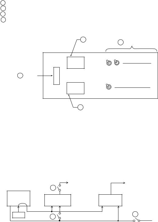
2.1 RC-1500-1T Control Panel
The figure which follows is an exploded view of the control panel.
EMG |
BATTERY |
BATTERY |
|
|
LIGHT |
MONITOR |
CHARGER |
For MSE (Maintenance free) |
|
|
IN USE LOW VOLT |
AUTO |
battery: |
OFF |
|
|
|||
|
|
OFF |
|
|
|
|
MANUAL |
|
AUTO |
|
|
|
|
|
|
|
|
3 BATTERY |
|
|
PRINTER |
CHARGER |
||
|
DSC |
NBDP |
Switch |
|
|
|
|
||
|
OFF |
AUTO |
|
|
1 EMG LIGHT |
2 BATTERY |
4 PRINTER |
Switch |
MONITOR |
selector switch |
|
Lamp |
|
Control description
1 EMG LIGHT switch
Turns the emergency lamps at the top of the console and external lamps (if applicable) on/off. If an external emergency light switch is provided (at the entrance of the radio room), the emergency lamps can also be switched on/off by this switch. (Flipping the switch up or down changes the state of the lamps; upward position is not always on.) The emergency lamps can be turned on at any time regardless of AC power status.
2 BATTERY MONITOR lamp
IN USE lamp (AC power failure: orange): Lights to alert that the AC power has failed and radio equipment are being powered by the radio battery (DC power) alone. When lit, only the equipment related to distress communications are powered. (Power is not supplied to PP-510 or console lights.)
LOW VOLT lamp (low battery voltage: red): Lights to alert that the battery voltage is below 22.5 VDC. (Aural alarm sounds until the voltage becomes 22.5 VDC.)
2 – 1
3 BATTERY CHARGER switch
Turns battery charger on/off. When charging, battery voltage is shown on the voltage meter on the AC/DC Radio Switch Box (in the lower-half side of the rack console).
AUTO: Automatically turns on the battery charger when the battery voltage is below 24 VDC and turns it off when the voltage exceeds 27.5 VDC. While the vessel is underway, set the switch in this position.
OFF: Disconnects the charger from the radio battery.
MANUAL: Charger the battery manually. When the voltage becomes 28 VDC change the switch to the "OFF" or "AUTO" position.
For maintenance free battery, keep the switch to the "AUTO" position to maintain the battery voltage between 25 V to 27 VDC.
4 PRINTER selector switch
Selects the input source equipment for the printer mounted on left of the radio console.
OFF: Printer is not connected.
DSC: Connects the printer to the DSC terminal.
NBDP
(INMARSAT) : Connects the printer to the NBDP terminal.
Note: Connects the printer to the Inmarsat C for the dual Inmarsat C type radio rack console.
AUTO: Connects the printer automatically.
For general telex communications, set the switch to NBDP position. You may select the DSC position to log communications made on DSC terminal, or to print out the DSC's internal settings.
Do not turn the switch while printing. Garbled printout will result.
2 – 2

Battery charging
Before operating the radio, check the battery voltage on the meter provided on the AC/DC Radio Switch Box. The battery voltage is maintained between 24 VDC and 27.5 VDC when the BATTERY CHARGER switch is in the AUTO position. Note that the OFF position of the BATTERY CHARGER switch may allow the voltage to drop below 24 VDC. In this case, charge the battery as follows:
1.Set the BATTERY CHARGER switch for MANUAL. Watch the charging current at the AC/
DC Radio Switch Box. (For a 200AH battery, the charging current will be around 20A at the start, and will be reduced gradually as charging proceeds.)  For maintenance free battery, set the BATTERY CHARGER switch for AUTO.
2.Turn the BATTERY CHARGER switch off or set it to AUTO when the charging current falls below 2A.
Note: If the AC power has failed, the radio battery automatically supplies power to the radio equipment regardless of BATTERY CHARGER switch position. The battery will not discharge as long as the AC power is alive.
Care of the lead-acid battery
The lead-acid battery powers distress-related communications equipment when the ship’s main power and emergency power fail, to enable communications in the event of distress. Therefore, follow the points mentioned below to keep the battery in good working order.
 WARNING
Keep sparks and lit smoking materials away from the lead-acid battery. Make sure the battery room is well ventilated.
The battery emits hydrogen gas which can cause explosion.
The electrolyte in the lead-acid battery contains sulfuric acid which can be harmful, particularly to the eyes.
If sulfuric acid contacts eyes, skin or clothing, flush directly with water. For eyes, contact a physician. Loss of eyesight can result.
The temperature of the electrolyte in the lead-acid battery should not exceed 45° C.
The electrolyte can cause explosion if it becomes too hot.
2 – 3

1. Confirming charging
Confirm that the BATTERY CHARGER switch on the control panel is set for AUTO. Further, confirm that the battery voltage meter on the AC/DC Radio Switch Box reads between 24 V and 27.5 VDC.
2. Checking specific gravity of electrolyte
The specific gravity of electrolyte is normal if it is 1.240 ± 0.010 (at 20° C).
3. Water supply
The electrolyte level can be seen on the battery. When the electrolyte falls below the highest graduation on the scale, fill to highest graduation with distilled water. Do not use diluted sulfuric acid or ordinary tap water—they will shorten battery life.
4. Cleaning
The battery and the area around it should always be clean and dry. Clean the battery case with a water-moistened cloth. Do not use chemical cleaners to clean the battery; they may crack the case. Kerosene may be used.
5. Environmental conditions
•Keep the battery out of direct sunlight.
•Coat the nuts and bolts which secure the battery contacts with anticorrosive paint for the lead-acid battery. Check yearly that bolts are securely fastened. Tighten nuts and bolts if necessary.
2.2 Maintenance
1. Cleaning display screens
Dust or dirt on the display screens of equipment may be removed with a soft cloth. Do not use chemical cleaners—they may remove paint and markings.
2. Cleaning floppy disk drives
The heads in the floppy disk drive of the DP-6 and FELCOM 12 should be cleaned regularly to prevent damage to floppy disks. Use a floppy disk cleaning kit. (FURUNO can supply a floppy disk cleaning kit. It is type MCD-2, code no. 000-116-420.)
Procedure
1. Insert a floppy disk cleaning kit in the drive.
2. Execute “Format” operation (in the F1 menu). The access lamp on the drive lights.
3.Wait until the access lamp goes off. Remove the disk. (Error message for formatting appears on the screen.)
2 – 4
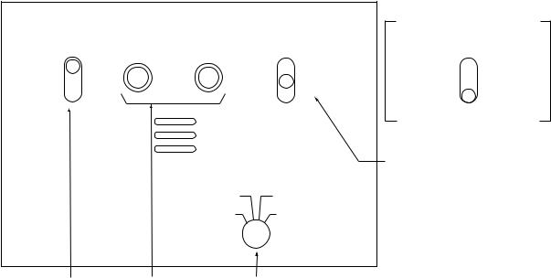
2.3 PP-510
Turning on the power
Turn on the POWER switch at the front of the printer. The POWER and ON LINE lamps light. The printer is now ready to print. If the ON LINE lamp is off, press the ON LINE switch to turn it on; you cannot print when the ON LINE lamp is off.
POWER
Switch
P.PARK FF |
LF |
NLQ ON LINE |
POWER Lamp
 P.OUT Lamp
These keys are operative when the
Lights when paper runs
printer is in off line state (ON LINE
out or internal error
lamp is off).
is found.
Toggles between on line and off line state.
Key description
[NLQ] (Near Letter Quality) key
Toggles between draft and NLQ print modes. Lighting the key selects near letter quality (high quality) print.
[LF] key
Advances the paper one line. Press and hold down the key to advance the paper continuously.
[FF] key
Advances the paper to the top of the next available form. The default form length is 11 inches.
2 – 5
[P.PARK] key
Backs the paper by maximum 18 inches. If the paper is not detected after backing it, the P. OUT lamp blinks three times and the printer stays in off line state.
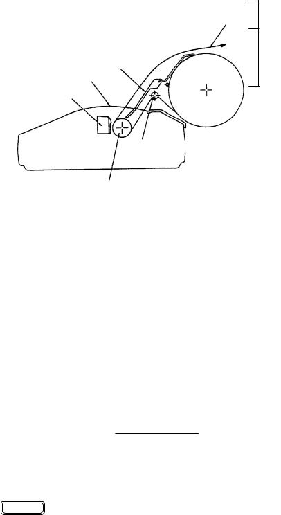
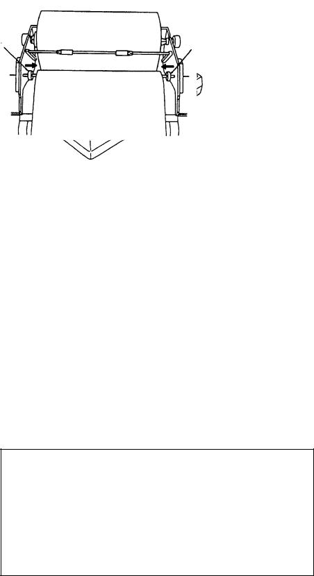
Loading roll paper
 CAUTION
Keep fingers away from edges on the printer and cover.
Edges can cut fingers.
This section shows you to load the roll paper.
Observe the following cautions when loading the paper:
•To prevent paper skewing or jamming, be sure the paper is positioned correctly.
•Never turn the platen knob too fast—gears may be damaged.
Paper
Paper
Support Bar
Printer Cover
Print Head
Paper Guide Bar
Platen Knob
PP-510, side view
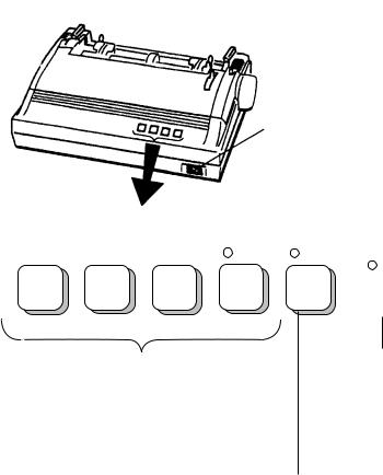
Removing remaining paper
1. Press the P. PARK switch to back up the paper. Turn off the power.
2 – 6
2.Unfasten screws A and push back B (for both right and left) shown below to remove the printer cover.
C |
Paper |
Paper
Cover
Screw
A
B
3.Swing out the paper cover by 100° to 120° then lift it up from the right-hand side to remove it from the printer.
4.Referring to the previous figure, lift the paper bail C. As shown in the figure which follows, remove the roll paper stay D and then take out the roll paper.
D
Loading new roll paper
5.Insert the roll bar into the roll paper from the left side. Set the roll paper to the roll paper cradle.
|
Roll Paper |
|
Roll Bar |
Type: A2 1PLT W |
|
Code No.: 000-134-903 |
|
|
|
Select |
|
|
Type: T-214 white OKFIP |
|
|
either. |
|
|
Code No.: 000-119-433 |
(no carbon) |
|
Roll Paper |
|
|
Cradle |
|
2 – 7
6.Pull the paper bail toward the front. Manually feed the paper over the paper guide bar and under the platen. Turn the platen knob clockwise to feed the paper so it reaches the paper guide bar.
Paper Guide
Bar
Paper Release Lever
Platen Knob
Paper Baii
Platen
7.Unlock the paper release lever to adjust the paper and then lock the paper release lever.
8.Slide the left and right guide rings to position the paper straightly.
Guide |
Guide |
Ring |
Ring |
9. Replace the paper cover, the printer cover and roll paper stay.
Remarks on Replacement of Ribbon Cassette
Change the ribbon when print darkness is no longer suitable to your needs.
Part |
Type |
Code No. |
|
|
|
Ribbon Cassette |
SP-16051NB |
000-133-029 |
|
|
|
The print head is hot after printing. Allow it cool down before touching it.
2 – 8

SSB Radiotelephone2
Part
The RC-1500-1T can be connected to the FS-1562 series or FS-5000 series FURUNO SSB Radiotelephone. Refer to respective operator's manual for operating information.
Part 2

MF/HF3DSC
Part

4. CALLING ............................................................................................................. |
4-1 |
|
4.1 |
All Ships Call ............................................................................................................................... |
4-1 |
|
4.1.1 Sending all ships call ......................................................................................................... |
4-1 |
|
4.1.2 Receiving all ships call....................................................................................................... |
4-3 |
4.2 |
Individual Call.............................................................................................................................. |
4-4 |
|
4.2.1 Sending individual call........................................................................................................ |
4-4 |
|
How to set working frequency............................................................................................ |
4-6 |
|
How to set DSC frequency................................................................................................. |
4-8 |
|
4.2.2 Receiving individual call................................................................................................... |
4-12 |
4.3 |
Group Call ................................................................................................................................. |
4-17 |
|
4.3.1 Sending a group call ........................................................................................................ |
4-17 |
|
4.3.2 Receiving a group call...................................................................................................... |
4-19 |
4.4 |
Geographical Area Call............................................................................................................. |
4-20 |
|
4.4.1 Sending a geographical area call..................................................................................... |
4-20 |
|
4.4.2 Receiving a geographical area call.................................................................................. |
4-23 |
4.5 |
Neutral Craft Call....................................................................................................................... |
4-24 |
|
4.5.1 Sending a neutral craft call .............................................................................................. |
4-24 |
|
4.5.2 Receiving a neutral craft call............................................................................................ |
4-25 |
4.6 |
Medical Transport Call .............................................................................................................. |
4-26 |
|
4.6.1 Sending a medical transport call...................................................................................... |
4-26 |
|
4.6.2 Receiving a medical transport call ................................................................................... |
4-27 |
4.7 |
Polling Call ................................................................................................................................ |
4-28 |
|
4.7.1 Sending a polling call ....................................................................................................... |
4-28 |
|
4.7.2 Receiving a polling call .................................................................................................... |
4-31 |
4.8 |
Position Call .............................................................................................................................. |
4-33 |
|
4.8.1 Position call: requesting other ship’s position .................................................................. |
4-34 |
|
4.8.2 Position call: other ship requests your position................................................................ |
4-36 |
4.9 |
PSTN Call ................................................................................................................................. |
4-39 |
|
4.9.1 Sending PSTN call, receiving acknowledge back (ACK BQ) .............................................. |
4-39 |
|
4.9.2 Sending PSTN call, receiving acknowledge back (QUEUE indication), |
|
|
ring back........................................................................................................................... |
4-43 |
|
4.9.3 Receiving PSTN call, sending acknowledge back (ACK BQ).......................................... |
4-47 |
|
4.9.4 PSTN call disconnection, receiving charge information |
|
|
(ship disconnects line) ..................................................................................................... |
4-48 |
|
4.9.5 PSTN call disconnection, receiving charge information |
|
|
(coast station disconnects line)........................................................................................ |
4-50 |
5. LOG FILE............................................................................................................. |
5-1 |
|
5.1 |
Log File Description .................................................................................................................... |
5-1 |
5.2 |
Opening a Log File...................................................................................................................... |
5-1 |
|
5.2.1 Distress log ........................................................................................................................ |
5-1 |
|
5.2.2 Ordinary log........................................................................................................................ |
5-3 |
|
5.2.3 Transmitted log .................................................................................................................. |
5-4 |
6. PREPARING SEND MESSAGES ........................................................................ |
6-1 |
|
6.1 |
Preparing Individual Call Messages............................................................................................ |
6-1 |
6.2 |
Preparing Group Call Messages................................................................................................. |
6-4 |
6.3 |
Preparing Geographical Area Call Messages............................................................................. |
6-5 |
6.4 |
Preparing PSTN Call Messages ................................................................................................. |
6-7 |
6.5 |
Preparing Test Call Messages .................................................................................................... |
6-8 |
iv


FOREWORD
Thank you for purchasing this DSC/Watch Receiver. We are confident you will discover why FURUNO has become synonymous with quality and reliability.
Dedicated in the design and manufacture of marine electronics equipment for half a century, FURUNO Electric Company has gained an unrivaled reputation as a world leader in the industry. This is the result of our technical excellence as well as our worldwide distribution and service network.
Please carefully read and follow the safety information and operating and maintenance instructions set forth in this manual before attempting to operate the equipment and conduct any maintenance. Your DSC/Watch Receiver will perform to the utmost of its ability only if it is operated and maintained in accordance with the correct procedures.
Features
Connected to an SSB radiotelephone, the DSC-60 generates and receives digital selective calls for quick and efficient establishment of distress, urgency, safety and routine communications with other ships and coast stations that install any MF/HF DSC facilities. Data is displayed on a large, easy-to-read backlit LCD. Operation is simplified by the use of few keys and easy-to-follow menus.
The main features are
•DSC Terminal, DSC Watch Receiver, DSC General Watch Receiver (option) and MF/HF Radiotelephone Remote Station all contained in a compact and light-weight cabinet.
•Fully meets GMDSS carriage requirements. Large LCD of 160-character indication.
•Conforms to the following standards and regulations:
IMO A. 694(17)
IMO A. 806(19)
IMO A. 813(19)
IMO MSC 68(68)
IEC-61097-3/8/9
IEC-60945 (3rd edition)
IEC-61162-1
ETS-300/338
ITU-R M.493-9, M.541-8, M.1082-1
•Scan watch feature scans operator-programmed DSC frequencies.
•Remote operation optionally available.
•Automatic position and time input and update with connection of EPFS (Electronic PositionFixing Equipment).
•Optional printer can automatically print out received messages and test results.
•Log stores 50 each of latest ordinary, distress and transmitted messages, in separate memory blocks.
vi
•Built-in intercom function provides voice communications between the DSC-60 and SSB radiotelephone.
•Optional built-in receiver board for DSC ship's business/routine frequencies.
•One-touch testing facility.
Program number
MAIN CPU 0550201002
MODEM 0550202001
vii
Loading...