


 Loading...
5" ECHO SOUNDR
LS-4100
TABLE OF CONTENTS
|
|
|
|
|
|
|
.....................................FOREWORD |
iii |
2. |
SYSTEM & INSTALLATION |
|
|
|
|
|
|
|
MENUS...................................... |
18 |
|
SYSTEM OVERVIEW........................ |
iv |
2.1 |
System Menu .......................... |
18 |
||
1. |
OPERATION ............................... |
1 |
3. |
MAINTENANCE, |
|
|
1.1 |
Control Description.................... |
1 |
|
TROUBLESHOOTING .............. |
21 |
|
1.2 |
Turning the Power On/Off ......... |
1 |
3.1 |
Maintenance ........................... |
21 |
|
1.3 |
Adjusting Display Contrast, |
|
3.2 |
Cleaning the Display Unit........ |
21 |
|
|
Brilliance.................................... |
2 |
3.3 |
Transducer Maintenance ........ |
21 |
|
1.4 |
Choosing a Display, Frequency.2 |
3.4 |
Replacing the Fuse ................. |
21 |
||
1.5 |
Menu Operating Procedure....... |
5 |
3.5 |
Battery Voltage Alert ............... |
21 |
|
1.6 |
Automatic Operation ................. |
5 |
3.6 |
Troubleshooting ...................... |
22 |
|
1.7 |
Manual Operation...................... |
6 |
3.7 |
Diagnostics ............................. |
22 |
|
1.8 |
Measuring Depth....................... |
8 |
3.8 |
Test Pattern............................. |
23 |
|
1.9 |
Choosing Picture Advanced |
|
3.9 |
Memory Clear ......................... |
23 |
|
|
Speed ........................................ |
8 |
|
|
|
|
1.10Suppressing Interference .......... |
9 |
4. |
INSTALLATION......................... |
24 |
||
1.11 Suppressing Low Level Noise... |
9 |
4.1 |
Display Unit............................. |
24 |
||
1.12Erasing Weak Echoes............. |
10 |
4.2 |
Thru-hull Mount Transducer.... |
24 |
||
1.13A-scope Display ...................... |
10 |
4.3 |
Transom Mount Transducer.... |
26 |
||
1.14Alarms ..................................... |
11 |
4.4 |
Inside-hull Transducer............. |
28 |
||
1.15Waypoints................................ |
12 |
4.5 |
Optional Triducer..................... |
29 |
||
1.16Setting Up Nav Data Displays.15 |
4.6 |
Optional Water |
|
|
||
1.17Other Menu Items ................... |
16 |
|
Temperature/Speed Sensor .... |
33 |
||
|
|
|
4.7 |
Wiring...................................... |
34 |
|
|
|
|
4.8 |
IEC 61162-1 Data Sentences.. 35 |
||
|
|
|
4.9 |
Installation Menu..................... |
36 |
|
|
|
|
SPECIFICATIONS ........................ |
SP-1 |
||
|
|
|
OUTLINE DRAWING |
|
|
|
|
|
|
INTERCONNECTION DIAGRAM |
|
|
|


 SAFETY INSTRUCTIONS
Safety Instructions for the Operator
 WARNING
Do not open the equipment.
There are no uer-serviceable parts inside.
Do not disassemble or modify the equipment.
Fire, electrical shock or serious injury can result.
Immediately turn off the power at the switchboard if the equipment is emitting smoke or fire.
Continued use of the equipment can cause fire or electrical shock. Contact a FURUNO agent for service.
Do not maneuver the vessel based on the depth indication alone.
Grounding may result.
Use the proper fuse.
Fuse rating is shown on the equipment. Use of a wrong fuse can result in damage to the equipment.
 CAUTION
Do no turn on the equipment with the transducer out of water.
The transducer may be damaged.
The picture is not refreshed when picture advancement is stopped.
Maneuvering the vessel in this condition may result in a dangerous situation.
Use the proper gain setting.
Incorrect gain may produce wrong depth indication, possibly resulting in a dangerous situation. See "Adjusting the gain" on page 7 for details.
NOTICE
The high quality LCD shows 99.99% of its pixels. The remaining .01% may drop out or brighten, due to the property of the LCD, however this is not a sign of malfunction.
A warning label is attached to the equipment. Do not remove the label. If the label is missing or damaged, contact a FURUNO agent or dealer.
WARNING |
Name: |
To avoid electrical shock, do not |
Warning Label |
remove cover. No user-serviceable |
Type: 02-146-1022 |
parts inside. |
|
|
Code No.: 100-306-050 |
i

Safety Instructions for the Installer
 WARNING
Turn off the power at the switchboard before beginning the installation.
Fire or electrical shock can result if the power is left on.
Be sure no water leaks in at the transducer or sensor mounting location.
Water leakage can sink the vessel. Also confirm that the transducer and sensor will not loosen by ship's vibration. The installer of the equipment is solely responsible for the proper installation of the equipment. FURUNO will assume no responsibility for any damage associated with improper installation.
Use the specified power cable.
Use of other power cable may result in fire.
 CAUTION
Do not install the equipment where air bubbles and noise are present.
Performance will be affected.
The following are guidelines for handling of the transducer cable.
-Do not locate near oils and fuels.
-Locate it in a safe place.
-Do no paint the cable.
The sheath of the cable is made of chloroprene rubber (or polychloride vinyl). For this reason do not paint the cable.
Do not turn on the equipment with the transducer out of water.
The transducer may be damaged.
Observe the following compass safe distances to prevent interference to a magnetic compass:
|
Standard |
Steering |
|
|
compass |
compass |
|
|
|
|
|
Display |
0.4 m |
0.3 m |
|
unit |
|||
|
|
||
|
|
|
ii

FOREWORD
A Word to LS-4100 Owners
Congratulations on your choice of the FURUNO LS-4100 5” Echo Sounder. We are confident you will see why the FURUNO name has become synonymous with quality and reliability.
For over 50 years FURUNO Electric Company has enjoyed an enviable reputation for innovative and dependable marine electronics equipment. This dedication to excellence is furthered by our extensive global network of agents and dealers.
This equipment is designed and constructed to meet the rigorous demands of the marine environment. However, no machine can perform its intended function unless operated and maintained properly. Please carefully read and follow the recommended procedures for operation and maintenance.
We would appreciate hearing from you, the end-user, about whether we are achieving our purposes.
Thank you for considering and purchasing FURUNO equipment.
Features
The FURUNO LS-4100 is a dual frequency (50 kHz and 200 kHz) monochrome LCD echo sounder. Comprised of a display unit and a transducer, the LS-4100 displays underwater conditions on a bright 5-inch monochrome LCD.
The main features of the LS-4100 are
•Bright 5-inch monochrome LCD gives excellent readability even in broad daylight.
•Automatic function permits unattended adjustment of range and gain. The range scale and gain automatically change to display the bottom in the darkest gray tone on the lower half of the screen.
•User-programmable nav data displays provide analog and digital nav data.
•Alarms: Bottom, Fish (bottom-lock and normal), Speed, Water Temperature and Arrival. (Speed and arrival alarms require appropriate sensor; water temperature alarm requires water temperature data.)
•White line feature helps discriminate fish lying near the bottom.
•Destination waypoint feature provides range, bearing, and time-to-go to destination waypoint. (up to 12 waypoints)
•Waterproof construction permits installation on open bridge.
iii
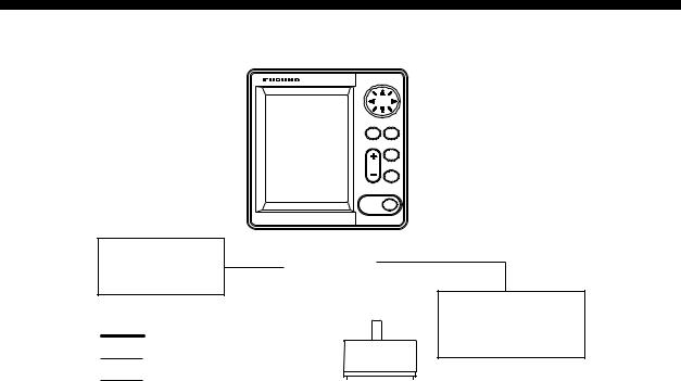
SYSTEM OVERVIEW
System configuration
GPS Navigator
or
Wind Indicator
:Standard
:Option
:User supply
|
DISPLAY UNIT |
MODE ESC |
LS-4100 |
MENU |
|
GAIN
RANGE
|
MARK |
Note: Contact your |
|
|
dealer for connection of |
ECHO SOUNDER POWER |
other equipment. |
|
LS-4100 |
BRILL |
|
|
|
|
|
|
|
|
|
Water temperature/ |
Power supply |
|
||||
12 VDC |
|
Speed sensor |
|||
|
Transducer |
ST-02MSB/ST-02PSB |
|||
|
|
||||
|
|
|
|
|
|
|
|
|
|
|
|
520-5PSD/520-5MSD/520-5PWD/
525-5PWD/525ST-MSD/525ST-PWD
Equipment lists
Standard supply
Name |
Type |
|
Code No. |
Qty |
Remarks |
||
Display Unit |
LS-4100 |
|
— |
1 |
|
|
|
|
520-5PSD |
000-015-204 |
|
Thru-hull mount |
|||
Transducer |
520-5MSD |
000-015-212 |
|
Thru-hull mount |
|||
520-5PWD |
000-015-126 |
1 |
Transom mount |
||||
|
|||||||
|
525-5PWD |
000-146-966 |
|||||
|
|
|
|
||||
Triducer (transducer |
525ST-MSD |
000-015-263 |
|
Thru-hull mount |
|||
plus spd/temp sensor) |
525ST-PWD |
000-015-261 |
|
Transom mount |
|||
Installation Materials |
• Tapping screw (4 pcs., 5 x 20 SUS304, 000-802-081) |
||||||
• Washer head screw B (4 pcs., M4 x 20 SUS304, 000-804-742) |
|||||||
(CP02-07401) |
|||||||
• Cable assy. (1 pc., MJ-A7SPF0005-020, 000-139-384, for power and data) |
|||||||
|
|||||||
Spare Parts |
Fuse (2 pc., FGMB 1A 125V, Code No. 000-114-805) |
||||||
(SP02-04801) |
|||||||
|
|
|
|
|
|
||
Template |
C22-00301 (000-146-981, for flush mount), |
|
|
|
|||
C22-00302 (000-146-982, for bulkhead) |
|
|
|
||||
|
|
|
|
||||
Optional equipment |
|
|
|
|
|
||
|
|
|
|
|
|
||
Name |
Type |
|
Code No. |
Qty |
Remarks |
|
|
Conversion Cable |
02S4147 |
|
000-141-082 |
1 |
For spd/temp sensor |
|
|
Water Temperature & |
ST-02MSB |
|
000-137-986 |
Select |
Thru-hull type |
|
|
ST-02PSB |
|
000-137-987 |
|
||||
Speed Sensor |
|
one |
|
|
|||
Inner Hull Kit S |
22S0191 |
|
000-802-598 |
1 |
|
|
|
iv
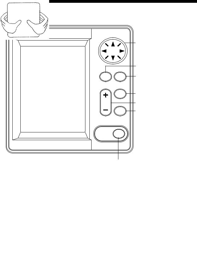
1. OPERATION
1.1 Control Description
Cursor Pad
Selects menu items; shifts VRM.
MODE
MENU
ESC
GAIN
RANGE
MARK
ECHO SOUNDER POWER
LS-4100 BRILL
Selects display mode.
Opens/closes menu; escapes from current operation.
Adjusts gain.
Selects basic display range.
Outputs L/L position to external equipment;
registers selected position as waypoint.
Long press: Turns power on/off. Momentary press: Adjusts display contrast
and brilliance.
Display unit
How to remove the hard cover
Place your thumbs at the center of the cover, and then lift the cover while pressing it with your thumbs.
1.2 Power On/Off
Press the [POWER/BRILL] key more than one second to turn on the power. The unit beeps, the startup screen appears, and then the equipment checks the ROM and RAM for proper operation and displays program number. (If “NG” (No Good) appears, try to press any key except the [POWER/BRILL] key to start operation. However, the equipment may not work properly. Contact your dealer.) You may
press any key after the completion of the equipment check to start operation sooner.
1
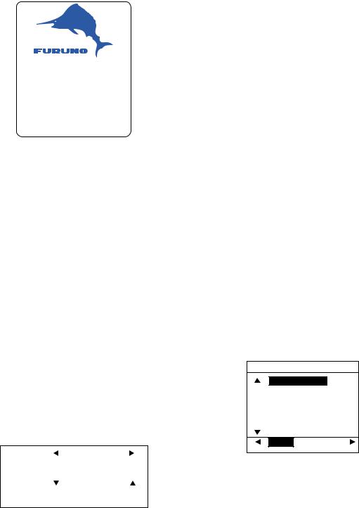
5" ECHO SOUNDER
LS-4100
FURUNO ELECTRIC CO., LTD.
ROM : OK RAM : OK
Program No: 0252318-01.**
** Program version no.
Start-up screen
To turn off the power, press and hold down the [POWER/BRILL] key until the screen goes blank. The time remaining until power is turned off is counted down on the screen.
Note: The example screens shown in this manual may not match the screens you see on your display. The screen you see depends on your system configuration and equipment settings.
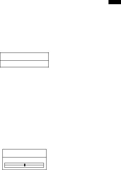
1.3Adjusting Display Contrast, Brilliance
1.Press the [POWER/BRILL] key momentarily to show the brilliance/contrast adjustment window.
|
|
Min |
|
|
Max |
|
CONTST |
|
|
4 |
|
|
|
|
|
|
|
|
|
|
|
|
Min |
|
|
Max |
|
|
|
|
|
|
|
|
BRILL |
|
|
|
|
|
|
|
|
4 |
|
|
||
|
|
|
|
|
|
|
Brilliance/contrast adjustment window
2.For contrast, press the [POWER/BRILL] key to adjust contrast cyclically. (You may also use
◄or ► on the Cursor Pad to adjust contrast.) (Adjustable range: 0 to 9)
3.To adjust brilliance, use ▲ or ▼. (Adjustable range: 0 to 4)
4.Press the [MENU/ESC] key to close the brilliance/contrast adjustment window.
Note 1: When the power is reapplied after turning off the equipment with minimum brilliance, minimum brilliance will be set after the equipment goes through its initial start up. (The start up screen appears with the maximum brilliance.) Adjust the brilliance as necessary.
Note 2: Setting windows other than those on menus are erased if there is no operation within about seven seconds.
1.4Choosing a Display, Frequency
Seven displays are available: single frequency (50 or 200 kHz), dual frequency, marker-zoom, bottom-zoom, bottom-lock, and nav data (two displays).
1.Press the [MODE] key to show the mode selection window.
MODE
SINGLE FREQ.
DUAL FREQ.
MARKER ZOOM
BOTTOM ZOOM
BOTTOM LOCK
NAV DATA-1
NAV DATA-2
50kHz 200kHz
Mode selection window
2.Press the [MODE] key again within seven seconds to choose a mode. You may also choose a mode with ▲ or ▼.
3.For modes other than DUAL FREQ, choose frequency. Press ◄ for 50 kHz or ► for 200 kHz.
4.Press the [MENU/ESC] key to close the window.
2

Single frequency display
50 kHz
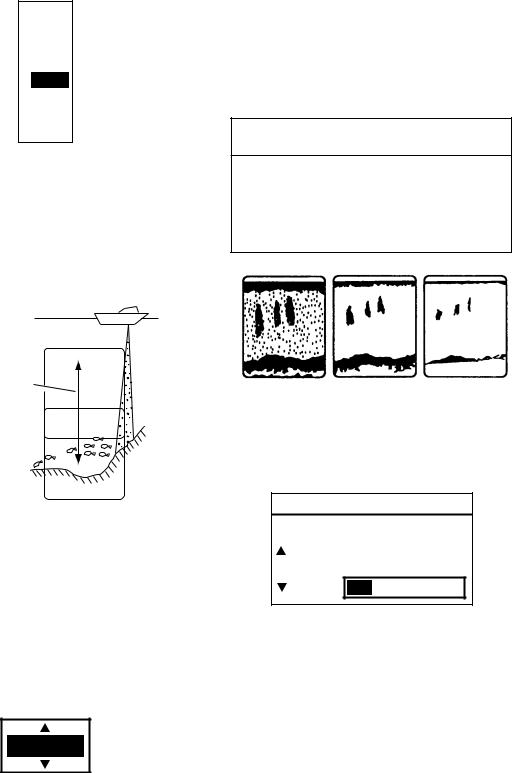
The sounder uses ultrasonic signals to detect bottom conditions. The lower the frequency of the signal, the wider the detection area. Therefore, the 50 kHz frequency is useful for general detection and judging bottom condition.
200 kHz
The higher the frequency of the ultrasonic signal the better the resolution. For this reason the 200 kHz frequency is ideal for detailed observation of fish schools.
50 kHz
200 kHz
Frequency and coverage area
Picture Advance Speed
Mode
(AUTO or MANUAL) Frequency
Minute |
|
|
|
|
|
|
|
|
|
50k |
|
1/1 |
|
|
||
|
|
|
|
|
|
|
|
|
|
|
|
|||||
|
|
|
|
|
|
|
|
|
0.0 |
0 |
|
|
|
|
||
Marker |
|
40.7° F |
|
|
|
|
|
|
|
|
||||||
|
|
Nav Display |
|
|
|
|
|
|
||||||||
(Shows time. |
|
16.2kt |
|
|
|
|
|
|
|
|
|
|
|
|||
|
|
Level Bar |
|
|
|
|
|
|
||||||||
Each bar |
|
|
|
|
|
|
|
|
||||||||
|
|
|
|
|
|
|
|
|||||||||
is 30 sec.) |
|
Fish |
Transmission 20 |
|
|
|
|
|||||||||
|
|
|||||||||||||||
|
|
|
|
|
||||||||||||
|
|
|
|
School |
Line |
|
|
|
|
|
|
|||||
Range Scale 
40
Bottom


 60
60

Depth  46.6
46.6

Typical 50 kHz display
Dual frequency display
The 50 kHz picture appears on the left; the 200 kHz picture on the right. This display is useful for comparing the same picture with two different transmitting frequencies.
50/200 |
1/1 |
0.0 |
0 |
50 kHz |
200 kHz |
picture |
picture |
20 |
20 |
40 |
40 |
60 |
60 |
49.6 |
80 |
80 |
Dual frequency display
Marker-zoom display
This mode expands chosen area of the normal picture to full vertical size of the screen on the left-half window. You may specify the portion to expand by operating the VRM (Variable Range Marker), which you can shift with ▲ or ▼. The area between the VRM and zoom range marker is expanded.
|
|
Single frequency display |
||
|
|
50k |
00 |
1/1 |
Zoomed17 |
0.0 |
|
||
|
|
|||
fish |
18 |
Fish |
|
Variable range |
school |
|
|||
school 10 |
marker |
|||
|
19 |
17.0 |
|
|
|
|
|
This section |
|
|
|
|
20 |
|
|
|
|
is zoomed |
|
|
20 |
|
|
|
|
|
|
|
|
|
21 |
|
30 |
|
|
|
|
|
|
25.0 |
22 |
|
40 |
Zoom marker |
|
|
|
|
|
Marker-zoom display |
||||
Marker-zoom display
3

Bottom-zoom display
This mode expands bottom and bottom fish in the range width set with ZOOM RANGE of the SYSTEM menu. This mode is useful for determining bottom contour. When the bottom depth increases, the display shift to keep the bottom echo at the lower part of the screen.
|
50k |
00 |
1/1 |
27 |
0.0 |
|
|
|
|
|
Single |
28 |
|
10 |
frequency |
|
|
display |
|
|
|
|
|
29 |
|
|
|
Bottom |
|
20 |
Zoom |
|
|
||
|
|
|
|
30 |
|
|
marker |
31 |
|
30 |
|
|
|
|
|
29.8 |
|
|
Switched with |
|
40 |
depth |
|
32 |
|
Bottom-zoom display
Bottom-zoom display
Bottom-lock display
The bottom-lock display provides a normal picture on the right half of the screen and a 15 feet (5 meter)* wide layer in contact with the bottom is expanded onto the left half of the screen. This mode is useful for detecting bottom fish.
* = Operator selectable
Bottom-lock display
|
|
|
|
|
|
|
|
|
|
|
|
50k |
|
|
1/1 |
|
|
|||
|
|
|
|
5 |
|
|
|
|
|
|
|
|
|
0 |
0 |
|
|
|
Zoom |
|
|
Zoomed |
|
|
|
|
|
|
|
|
|
|
|
|
|
|
|
|
|||
|
|
|
|
|
|
|
|
|
|
|
|
|
|
|
|
|
marker |
|||
|
fish |
4 |
|
|
|
|
|
|
|
|
|
10 |
|
|
|
|||||
|
|
|
|
|
|
|
|
|
|
|||||||||||
|
|
|
|
|
|
|
|
|
|
|
|
|
|
|
|
|
|
This section |
||
|
|
|
|
|
|
|
|
|
|
|
|
|
|
|
|
|
|
|
||
|
|
|
|
|
|
|
|
|
|
|
|
|
|
|
|
|
|
|
|
|
|
|
|
|
3 |
|
|
|
|
|
|
|
|
|
|
|
|
|
|
||
|
|
|
|
|
|
|
|
|
|
|
|
|
|
|
|
|
|
|||
|
|
|
|
|
|
|
|
|
|
|
|
|
|
|
|
|
|
|||
|
|
|
|
2 |
|
|
|
|
|
|
|
|
|
20 |
|
|
|
is zoomed |
||
|
|
|
|
|
|
|
|
|
|
|
|
|
|
|
||||||
|
|
|
|
|
|
|
|
|
|
|
|
|
|
|
|
|||||
|
|
|
|
|
|
|
|
|
Fish |
|
|
|
|
|
Single |
|||||
|
|
|
|
|
|
|
|
|
|
|
|
|
|
|
|
|||||
|
|
|
|
1 |
|
|
|
|
|
30 |
|
|
|
frequency |
||||||
|
|
|
|
|
|
|
|
|
|
|
||||||||||
21.7 |
|
|
|
|
|
school |
|
|
|
display |
||||||||||
|
|
|
|
|
|
|
|
|||||||||||||
|
|
|
|
|
|
|
|
|
|
|||||||||||
|
|
|
|
|
|
|
|
|
|
|
|
|
|
|
|
|
||||
|
|
|
|
|
|
|
|
|
|
|
|
|
|
|
|
|
||||
0 |
|
|
|
|
|
|
|
|
|
40 |
|
|
|
|
||||||
|
|
|
|
|
|
|
|
|
|
|
|
|
|
|
|
|
||||
|
|
|
|
|
|
|
|
|
|
|
|
|
|
|
|
|
|
|
|
|
Bottom displayed flat
Bottom-lock display
Nav data displays
The nav data displays appear on the left of the screen. Data other than depth requires appropriate sensor.
You can display between two and four items in a nav data display and choose the item and order to display them. See paragraph 1.16 to choose the items to display, “NAV DATA-1” and “NAV DATA-2” in paragraph 2.1 to choose the number of items to display.
Depth
69.4m
Temperature
65.5° F
Odometer
56nm
Trip meter
10.0nm
NAV DATA-1 display
XTE |
|
|
|
|
|
0.25nm |
|
||
1 |
0.5 |
0 |
0.5 |
1 |
Speed |
|
|
|
|
|
60 |
|
|
|
|
50 |
|
|
|
|
40 |
|
|
|
30 |
|
|
|
|
20 |
|
|
17.2 |
|
10 |
kt |
|
||
0 |
|
|||
NAV DATA-2 display
Sample NAV DATA displays (Default setting)
4
1.5Menu Operating Procedure
The LS-4100 has three menus: Main, System and Installation. Below is the basic menu operating procedure.
1.Press the [MENU/ESC] key to open the main menu. Page 1 or Page 2 of the main menu appears depending on the page last used.
AUTO MODE |
Off |
|
SHIFT |
: |
0ft |
PIC. ADVANCE : 1/1 |
|
|
NOISE LIMIT |
: Off |
|
CLUTTER |
: Off |
|
SIGNAL LEVEL : Off |
|
|
A-SCOPE |
: Off |
|
HUE |
: Day |
|
WHITE LINE |
: Off |
|
DEEP GAIN |
: Low |
|
(1/2)
[MENU]: Exit
Note: SHIFT and CLUTTER are
not available in the auto mode. Page no.
Main menu, page 1
2.Use ▲ or ▼ to select an item. To view page 2 of the main menu, press ▼ until showing the display below.
GOTO WPT |
|
Off |
WAYPOINT LIST... |
||
TRIP RESET? |
|
|
GAIN ADJ 200 |
: +0 |
|
GAIN ADJ 50 |
: +0 |
|
DRAFT |
: 0.0ft |
|
ALARM MENU... |
|
|
|
|
|
|
|
SYSTEM MENU... |
(2/2) |
||
|
|
|
|
[MENU]: Exit |
|
|
|
Main menu, page 2
3.Press ► to show selected item’s options window. The example shown at the top of the right column is the options window for AUTO MODE.
Off
Cruising
Fishing
Auto mode options window
4.Use ▲ or ▼ to choose option or set numeric value.
5.Press the [MENU/ESC] key to close the menu, or press ◄ to continue menu operation.
1.6 Automatic Operation
How automatic operation works
The automatic function automatically chooses the proper gain, range scale and clutter. It works as follows:
•The range changes automatically to display the bottom echo on the screen.
•The gain is automatically adjusted to display the bottom echo in the darkest tone.
•Clutter (on the menu), which suppresses low-level noise, is automatically adjusted.
Choosing automatic operation
The automatic mode provides two choices of modes: cruising and fishing.
1.Press the [MENU/ESC] key to open the main menu.
2.Press ▲ to choose AUTO MODE from page 1 of the menu.
3.Press ► to open the mode options window.
4.Choose Cruising or Fishing as appropriate.
“Cruising” is for tracking the bottom; “Fishing” is for searching fish schools. Since “Cruising” uses a higher clutter rejection setting than fishing, it is not recommended for fish detection - weak fish echoes may not be displayed. “Fishing” clearly displays weaker echoes.
5
5.Press the [MENU/ESC] key to close the menu.
The auto mode in use is shown as  (Auto-Fishing) or
(Auto-Cruising) at the top left corner on the screen.
Note: When in the auto mode, SHIFT and CLUTTER cannot be adjusted manually.
Range offset
To display the bottom tail in detail in the automatic mode, offset the range as below.
1.Press the [+] or [-] key of the [RANGE] key.
AUTO RANGE OFFSET
+0 ft
Auto range offset window
2.Press the [+] or [-] key of the [RANGE] key again to choose offset desired (range: -100 to +300 ft). Note that if the basic range is changed the offset is returned to “0”.
3.Press the [MENU/ESC] key to finish.
Gain offset
Gain offset lets you override automatic gain adjustment.
1. Press the [GAIN] key.
AUTO GAIN OFFSET
 Min ±0 Max
Auto gain offset window
2.Press ◄ or ► key to offset gain (setting range –5 to +5). The gain selected is shown at the top of the screen as
G (Gain) + (or -) XX (offset value).
3.Press the [MENU/ESC] key to finish.
1.7 Manual Operation
Choosing the manual mode
1.Press the [MENU/ESC] key to open the main menu.
2.Press ▲ to choose AUTO MODE from page 1 of the menu.
3.Press ► to show the window.
4.Choose Off with ▲.
5.Press the [MENU/ESC] key to close the menu. MANUAL appears at the top left corner on the screen.
Choosing range
The basic range and range shifting functions used together give you the means to choose the depth you can see on the screen. The basic range can be thought of as providing a “window” into the water column and range shifting as moving the “window” to the desired depth.
Choosing basic range
The basic range may be chosen with the [RANGE] key from the eight ranges shown in the table shown below. (“P/B” in the table means Passi/Braza.) The setting range can be arranged through the SYSTEM menu.
Default ranges
Unit |
|
|
|
Basic Range |
|
|
|||
1 |
2 |
3 |
4 |
5 |
6 |
7 |
8 |
||
|
|||||||||
meters |
5 |
10 |
20 |
40 |
80 |
150 |
200 |
300 |
|
feet |
15 |
30 |
60 |
120 |
200 |
400 |
600 |
1000 |
|
fathoms |
3 |
5 |
10 |
20 |
40 |
80 |
100 |
150 |
|
hiro* |
4 |
8 |
15 |
30 |
50 |
100 |
150 |
200 |
|
P/B |
3 |
5 |
10 |
30 |
50 |
100 |
150 |
200 |
|
*Japanese unit of depth measurement
1.Press the [+] or [-] key of the [RANGE] key and the display should now look something like the one on at the top of the next page.
2.Press the [+] or [-] key of the [RANGE] key again to choose a basic range.
6
1000ft
600ft
400ft
200ft
120ft
60ft
30ft
15ft
Basic ranges (default)
3.Press the [MENU/ESC] key to close the window.
Shifting the range
The basic range may be shifted up or down in the manual mode as follows:
Window can be shifted up and down to select the depth.
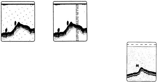
Adjusting the gain
The [GAIN] key adjusts the sensitivity of the receiver. Generally, use a higher gain setting for greater depths and a lower setting for shallower waters.
 CAUTION
Use the proper gain setting.
Incorrect gain may produce wrong depth indication, possibly resulting in a dangerous situation.
Gain too high Gain proper Gain too low
Examples of proper and improper gain
1.Press the [GAIN] key and the display shown below appears.
Display
Range and display shift concept
1.Press the [MENU/ESC] key to open the main menu.
2.Choose SHIFT from page 1 of the menu.
3.Press ► to open the shift options window.
0ft
Shift window
4.Use ▲ or ▼ to choose amount of shift desired.
5.Press the [MENU/ESC] key to close the window.
Note: The picture may not be displayed if the amount of shift is greater than actual depth.
GAIN
 Min Max
|
|
|
|
|
200k |
|
|
|
2 |
|
|
|
|
|
50k 3
Gain adjustment window
2.When using the dual frequency display, press ▲ or ▼ to choose frequency.
3.Press the [GAIN] key to set. (You may also use ◄ or ►.) Adjust so that a slight amount of noise remains on the screen.
4.Press the [MENU/ESC] key to close the gain adjustment window.
7
1.8 Measuring Depth
The VRM (Variable Range Marker) functions to measure the depth to fish schools, etc.
1.Press ▲ or ▼ to place the VRM on the object which you wish to measure range.
2.Read the VRM depth just above the VRM.
50k  1/1
1/1
0
VRM
VRM depth 20
39.8
40
60

 49.6
49.6


 80
80

How to measure depth with the VRM
1.9Choosing Picture Advance Speed
The picture advance speed determines how quickly the vertical scan lines run across the screen. When choosing a picture advance speed, keep in mind that a fast advance speed will expand the size of the fish school horizontally on the screen and a slow advance speed will contract it. Note that the picture is not refreshed when picture advancement is stopped. Therefore, use caution when steering the vessel under this condition.
Fast |
Slow |
Picture and picture advancement speed
1.Press the [MENU/ESC] key to open the main menu.
2.Choose PIC. ADVANCE from page 1 of the menu.
3.Press ► to show the options window.
|
Stop |
( |
||
1/16 |
|
|||
|
Slow |
|||
1/8 |
|
|
|
|
|
|
|
||
1/4 |
|
|
|
|
1/2 |
|
|
|
|
|
1/1 |
|
|
|
2/1 |
|
|
|
|
|
Fast |
|||
4/1 |
|
|||
|
) |
|||
Picture advance options window
4.Use ▲ or ▼ to choose picture advance speed desired. The fractions in the options window denote the number of scan lines produced per transmission. For example, 1/8 means one scan line is produced every 8 transmissions. “Stop” freezes the display and it is convenient for taking a photo.
 CAUTION
The picture is not refreshed when picture advancement is stopped.
Maneuvering the vessel in this condition may result in a dangerous situation.
5.Press the [MENU/ESC] key to close the menu.
8
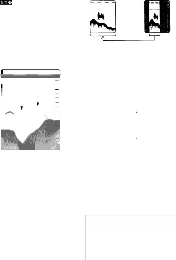
1.10Suppressing Interference
Interference from other acoustic equipment operating nearby or other electronic equipment on your boat may show itself on the display as shown in the figure below.
To suppress interference, do the following:
1.Press the [MENU/ESC] key to open the main menu.
2.Use ▲ or ▼ to choose NOISE LIMIT from page 1 of the menu.
3.Press ► to show the options window.
4.Use ▲ or ▼ to choose the degree of suppression desired; Off, Low, Medium, or High (highest).
5.Press the [MENU/ESC] key to close the menu.
Interference from |
Electrical interference |
other sounder |
|
Forms of interference
Turn the noise limiter off when no interference exists, otherwise weak echoes may be missed.
1.11Suppressing Low Level Noise
Low intensity “speckles” may appear over most of screen. This is mainly due to sediment in the water or noise. These can be suppressed by adjusting CLUTTER on the menu. When the automatic mode is on, clutter is automatically rejected. To suppress low level noise in manual sounder operation, do the following:
1.Press the [MENU/ESC] key to open the main menu.
2.Use ▲ or ▼ to choose CLUTTER from page 1 of the menu.
3.Press ► to show the options window.
4.Use ▲ or ▼ to choose the degree of suppression desired; 1, 2, 3 ,4, 5 or
6.The higher the number the greater the suppression.
5.Press the [MENU/ESC] key to close the menu.
To turn off low-level noise suppression, choose Off at step 4 and then press the [MENU/ESC] key.
Clutter appearance
9
Loading...