


GP-7000F
COLOR GPS/PLOTTER/SOUNDER
GP-7000F
Back

Thepaperusedinthismanual
iselementalchlorinefree.
FURUNO Authorized Distributor/DealerFURUNO Authorized Distributor/Dealer
9-52
A
shihara-cho,9-52
A
shihara-cho,
Nishinomi
y
a 662-8580, JAPANNishinomi
y
a 662-8580, JAPAN
Tele
p
hone :Tele
p
hone : 0798-65-21110798-65-2111
FaxFax 0798-65-42000798-65-4200
::
FIRST EDITION :FIRST EDITION :AUG.AUG. 20042004
Printed in JapanPrinted in Japan
A
ll ri
g
hts reserved.
A
ll ri
g
hts reserved.
B2B2 :: OCT.OCT. 14, 200514, 2005
Pub. No.Pub. No. OME-44291OME-44291
*
0
0014913701*
*
0
0014913701*
*
0
0014913701*
*
0
0014913701*
(( HIMAHIMA ))
GP-7000FGP-7000F
* 0 0 0 1 4 9 1 3 7 0 1 ** 0 0 0 1 4 9 1 3 7 0 1 *
*
O
ME
4
4291B20*
*
O
ME
4
4291B20*
*
O
ME
4
4291B20*
*
O
ME
4
4291B20*
* O M E 4 4 2 9 1 B 2 0 ** O M E 4 4 2 9 1 B 2 0 *

IMPORTANT NOTICE
No part of this manual may be copied or reproduced without written permission.
If this manual is lost or worn, contact your dealer.
The contents of this manual and equipment specifications are subject to change without
notice.
The example screens (or illustrations) shown in this manual may not match the screens
you see on your display. The screen you see depends on your system configuration and
equipment settings.
This manual is intended for use by native speakers of English.
FURUNO will assume no responsiblity for the damage caused by improper use or
modification of the equipment or claims of loss of profit by a third party.
i
SAFETY INSTRUCTIONS
Do not disassemble or modify the
equipment.
Fire, electrical shock or serious injury
can result.
Do not open the equipment.
Immediately turn off the power at the
switchboard if the equipment is emitting
smoke or fire.
Continued use of the equipment can
cause electrical shock.
Do not operate the equipment with wet
hands.
Electrical shock can result.
Use the proper fuse.
Fuse rating is shown on the power cable.
Use of a wrong fuse can result in damage
to the equipment.
Hazardous voltage which can cause
electrical shock, burn or serious injury
exists inside the equipment. Only qualified
personnel should work inside the equipment.
WARNINGWARNING
CAUTION
Do not use the equipment for other than
its intended purpose.
No one navigation device should ever be
solely replied upon for the navigation of
a vessel.
Always confirm position against all available
aids to navigation, for safety of vessel and
crew.
Do not turn on the equipment with the
transducer out of water.
The transducer may be damaged.
Use the proper gain setting.
Incorrect gain may produce wrong depth
indication, possibly result ing in a
dangerous situation. See "Adjusting the
gain" on page 10-11.
The picture is not refreshed when
picture advancement is stopped.
Maneuvering the vessel in this condition
may result in a dangerous situation.
A warning label is attached to the equip-
ment. Do not remove the label. If the
label is missing or illegible, contact
a FURUNO agent or dealer.
WARNING
To avoid electrical shock, do not
remove cover. No user-serviceable
parts inside.
Name: Warning Label (1)
Type: 86-003-1011-1
Code No.: 100-236-231
The TFT LCD is constructed using the
latest LCD techniques, and displays
99.99% of its pixels. The remaining 0.01%
of the pixels may drop out or blink, how-
ever this is not an indication of malfunc-
tion.
About the TFT LCD
Do not maneuver the vessel based
on the depth indication alone.
Grounding may result.
ii

iii
FOREWORD
Congratulations on your choice of the FURUNO GP-7000F COLOR
GPS/PLOTTER/SOUNDER. We are confident you will see why the FURUNO
name has become synonymous with quality and reliability.
For over 50 years FURUNO Electric Company has enjoyed an enviable
reputation for innovative and dependable marine electronics equipment. This
dedication to excellence is furthered by our extensive global network of agents
and dealers.
This equipment is designed and constructed to meet the rigorous demands of
the marine environment. However, no machine can perform its intended function
unless installed, operated and maintained properly. Please carefully read and
follow the recommended procedures for operation and maintenance.
Features
The GP-7000F provides a totally integrated GPS receiver, color video plotter and
color video sounder.
The GPS receiver tracks up to 13 satellites (GPS: 12, WAAS: 1) simultaneously,
and an 8-state Kalman filter ensures optimum accuracy in determination of
vessel position, course and speed.
• C-MAP NT + and MAX chart card (SD) is available.
• Comprehensive navigation data displays.
• Bright 7-inch color TFT LCD with brilliance control.
• Automatic coastline chart loading.
• Position display in latitude and longitude, Loran C TD.
• Alarms: Arrival, Anchor Watch, Cross-track Error, Speed, Grounding, Fish,
Depth, Temperature.
• Man overboard feature records latitude and longitude coordinates at the time
of man overboard.
• “Highway” display provides graphic presentation of ship’s track and is useful
for monitoring cross track error.
• Automatic or manual video sounder operation.

iv
TABLE OF CONTENTS
SYSTEM CONFIGURATION.............................................................................. viii
1. OPERATIONAL OVERVIEW .........................................................................1-1
1.1 Display Unit Controls......................................................................................................1-1
1.2 Loading an SD
TM
Chart Card..........................................................................................1-2
1.3 Turning the Power On/Off...............................................................................................1-3
1.4 Adjusting Brilliance and Contrast....................................................................................1-4
1.5 Selecting a Display.........................................................................................................1-5
1.6 Soft Keys........................................................................................................................1-5
1.7 MOB Mark ......................................................................................................................1-6
1.7.1 Entering the MOB mark, setting MOB as destination........................................1-6
1.7.2 Deleting the MOB mark.....................................................................................1-7
1.8 Menu Operation..............................................................................................................1-7
1.9 Simulation Mode.............................................................................................................1-9
2. PLOTTER DISPLAYS....................................................................................2-1
2.1 Presentation Modes........................................................................................................2-1
2.1.1 North-up ............................................................................................................2-1
2.1.2 Course-up..........................................................................................................2-2
2.1.3 Auto course-up..................................................................................................2-2
2.2 Cursor.............................................................................................................................2-3
2.2.1 Turning on the cursor, shifting the cursor ..........................................................2-3
2.2.2 Moving the cursor to the center of the screen...................................................2-3
2.2.3 Displaying data..................................................................................................2-4
2.3 Selecting Chart Scale/Range.........................................................................................2-4
2.4 Navigation Data Display.................................................................................................2-5
2.5 Compass Display............................................................................................................2-6
2.6 Highway Display.............................................................................................................2-7
2.7 GPS Status Display........................................................................................................2-8
2.8 Tide, Celestial Display....................................................................................................2-9
2.9 Graph Display...............................................................................................................2-10
2.10 Wind Display ..............................................................................................................2-11
2.11 NAVDATA Window......................................................................................................2-12
3. TRACK...........................................................................................................3-1
3.1 Selecting Active Track....................................................................................................3-1
3.2 Displaying Track.............................................................................................................3-2
3.3 Changing Track Color.....................................................................................................3-2
3.4 Stopping, Restarting Plotting..........................................................................................3-2
3.5 Hiding the Track .............................................................................................................3-3
3.6 Track Plotting Method and Interval.................................................................................3-3
3.6.1 Track plotting method........................................................................................3-3
3.6.2 Track plotting interval ........................................................................................3-4
3.7 Erasing Track .................................................................................................................3-4

v
4. WAYPOINT.....................................................................................................4-1
4.1 Entering Waypoints........................................................................................................ 4-1
4.1.1 Entering a waypoint at own ship position or cursor position............................. 4-1
4.1.2 Entering a waypoint from the waypoint list ....................................................... 4-3
4.1.3 Entering a waypoint/MOB mark with an external event switch ......................... 4-4
4.2 Editing Waypoint Data................................................................................................... 4-5
4.2.1 Editing waypoint data from the waypoint list..................................................... 4-5
4.2.2 Editing a waypoint from the plotter display ....................................................... 4-5
4.3 Erasing Waypoints......................................................................................................... 4-6
4.3.1 Erasing a waypoint directly from the plotter display.......................................... 4-6
4.3.2 Erasing a waypoint from the waypoint list......................................................... 4-6
4.4 Searching, Sorting Waypoints........................................................................................ 4-7
4.5 Other Waypoint List Functions....................................................................................... 4-8
4.5.1 Filtering waypoints by mark shape ................................................................... 4-8
4.5.2 Hiding or showing waypoints ............................................................................ 4-9
4.5.3 Searching waypoints......................................................................................... 4-9
5. ROUTE...........................................................................................................5-1
5.1 Entering Routes.............................................................................................................5-1
5.2 Changing the Route Name/Comment............................................................................ 5-2
5.3 Connecting Routes........................................................................................................ 5-3
5.4 Inserting Waypoints....................................................................................................... 5-4
5.5 Removing Waypoints from a Route............................................................................... 5-5
5.6 Information on Route Report ........................................................................................ 5-6
5.7 Changing the Color of Route Line ................................................................................ 5-7
5.8 Searching Routes.......................................................................................................... 5-8
5.9 Reversing the Waypoints Order in a Route................................................................... 5-8
5.10 Erasing Routes............................................................................................................ 5-8
6. NAVIGATION..................................................................................................6-1
6.1 Navigating to Quick Points............................................................................................. 6-1
6.2 Navigating to Waypoints................................................................................................ 6-4
6.3 Following a Route.......................................................................................................... 6-5
6.4 Cancelling Navigation.................................................................................................... 6-6
6.5 Affecting the Destination Set at Primary Unit to Secondary........................................... 6-7
7. ALARMS ........................................................................................................7-1
7.1 Audible Alarm On/Off ..................................................................................................... 7-2
7.2 Arrival Alarm................................................................................................................... 7-2
7.3 XTE (Cross-Track Error) Alarm...................................................................................... 7-3
7.4 Temperature Alarm ........................................................................................................ 7-4
7.5 Anchor Alarm ................................................................................................................. 7-5
7.6 STW Alarm.....................................................................................................................7-5
7.7 Depth Alarm................................................................................................................... 7-6
7.8 Grounding Alarm............................................................................................................ 7-7
8. CUSTOMIZING YOUR UNIT..........................................................................8-1
8.1 GENERAL Menu............................................................................................................ 8-1
8.2 MAP Menu..................................................................................................................... 8-2

vi
8.3 ADV ANCED Menu..........................................................................................................8-6
8.4 INFO Menu.....................................................................................................................8-9
8.5 FIND Menu.....................................................................................................................8-9
9. DATA TRANSFER..........................................................................................9-1
9.1 Memory Card Operations...............................................................................................9-1
9.1.1 Selecting the card slot to use ............................................................................9-1
9.1.2 Formatting memory cards .................................................................................9-2
9.1.3 Saving data to a memory card...........................................................................9-2
9.1.4 Playing back data from a memory card.............................................................9-3
9.2 Sending/Receiving Data.................................................................................................9-3
9.2.1 Sending/receiving waypoints data.....................................................................9-3
9.2.2 Sending/receiving route data.............................................................................9-5
9.3 Waypoint, Route Format..............................................................................................9-6
10. VIDEO SOUNDER OPERATION...............................................................10-1
10.1 Sounder Display.........................................................................................................10-2
10.1.1 Description of sounder display........................................................................10-2
10.1.2 Selecting a sounder display ............................................................................10-4
10.2 Automatic Sounder Operation....................................................................................10-8
10.2.1 How the automatic sounder works..................................................................10-8
10.2.2 Types of automatic sounder mode..................................................................10-9
10.2.3 How to enable automatic sounder operation................................................... 10-9
10.3 Manual Sounder Operation......................................................................................10-10
10.3.1 Selecting the manual mode...........................................................................10-10
10.3.2 Selecting display range.................................................................................10-10
10.3.3 Adjusting the gain..........................................................................................10-11
10.4 Measuring Depth, Time............................................................................................10-12
10.5 Reducing Interference..............................................................................................10-13
10.6 Reducing Low Level Noise.......................................................................................10-14
10.7 Erasing Weak Echoes.............................................................................................. 10-15
10.8 White Marker............................................................................................................10-16
10.9 Picture Advance Speed............................................................................................10-17
10.10 Alarms ....................................................................................................................10-18
10.10.1 Audio alarm On/Off......................................................................................10-18
10.10.2 Fish alarm ...................................................................................................10-19
10.10.3 Fish alarm (B/L)...........................................................................................10-19
10.11 Water Temperature Graph......................................................................................10-20
10.12 Reviewing Past Picture ..........................................................................................10-20
10.13 Displaying Nav Data...............................................................................................10-21
10.14 SOUNDER SETUP Menu.......................................................................................10-22
10.15 Interpreting the Sounder Display............................................................................10-24
11. MAINTENANCE & TROUBLESHOOTING................................................11-1
11.1 Maintenance...............................................................................................................11-1
11.2 Replacement of Fuse..................................................................................................11-2
11.3 Replacing of Battery ...................................................................................................11-2
11.4 Simple Troubleshooting..............................................................................................11-3
11.5 Diagnostics.................................................................................................................11-5

vii
11.5.1 RAM menu.................................................................................................... 11-5
11.5.2 Dim menu...................................................................................................... 11-6
11.5.3 Cartridge ....................................................................................................... 11-6
11.5.4 Serial ports.................................................................................................... 11-7
11.6 Program No. ............................................................................................................ 11-7
11.7 Clearing the Memory ................................................................................................ 11-8
11.8 GPS Cold Start......................................................................................................... 11-8
APPENDIX ......................................................................................................AP-1
Menu Tree....................................................................................................................... AP-1
What is WAAS? .............................................................................................................. AP-5
World Time Chart............................................................................................................ AP-6
SPECIFICATIONS........................................................................................... SP-1
INDEX............................................................................................................... IN-1
Notice for SD
TM
Card
We confirmed that the following brands of SD
TM
cards can be used for
uploading/downloading data. For SD
TM
cards other than listed below, we have
not yet confirmed if they are compatible with GP-7000/F.
• Kingstone
• Viking
• EP Memory
• SANDISK
• Panasonic
• Toshiba
• PQI
• Power Quotient
• ADTEC
• buffalo
• I/O DATA
• Hagiwara Sys-com
• LEXAR
viii
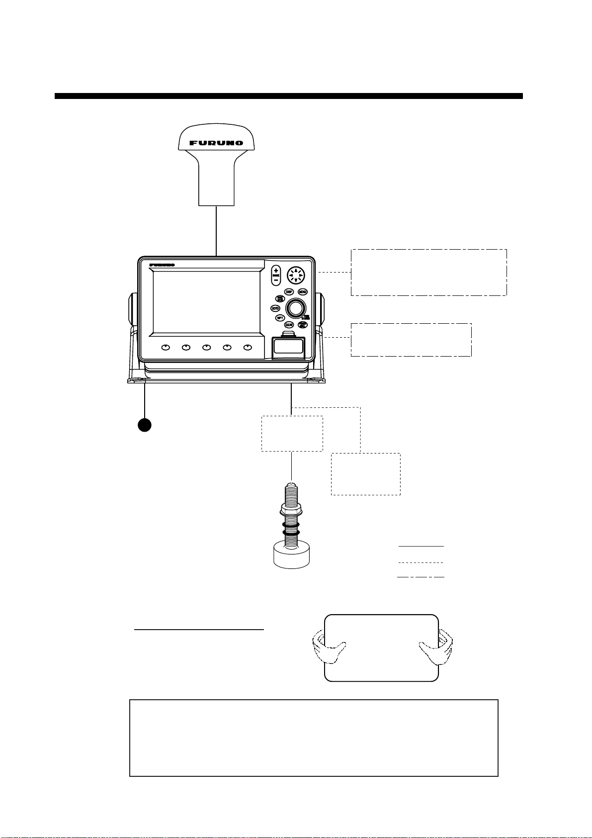
SYSTEM CONFIGURATION
TRANSDUCER
Speed/Water
Temp Sensor
(option)
Distributor
MB-1000*
* Required when using
1 kW transducer.
Power Source
12-24 VDC
: Option
: Standard
: User Supply
NMEA1 and NMEA2 ports:
Radar, autopilot, video sounder,
temperature indicator, etc.
PC/NMEA IN port:
PC, NMEA device, buzzer
ANTENNA UNIT GPA-017
DISPLAY UNIT
GP-7000F
How to remove the hard cover
Place your thumbs at the center
of the cover, and then lift the cover
while pressing it with your thumbs.
This GPS receiver complies with Canadian standard RSS-210 (Low Power
License-Exempt Radio communication Devices).
Operation is subject to the following two conditions:
(1) this device may not cause interference, and
(2) this device must accept any interference, including interference that may
cause undesired operation of the device.
1-1
1. OPERATIONAL OVERVIEW
This chapter acquaints you with the basics of your unit–from turning on the
power to the soft key menu operation.
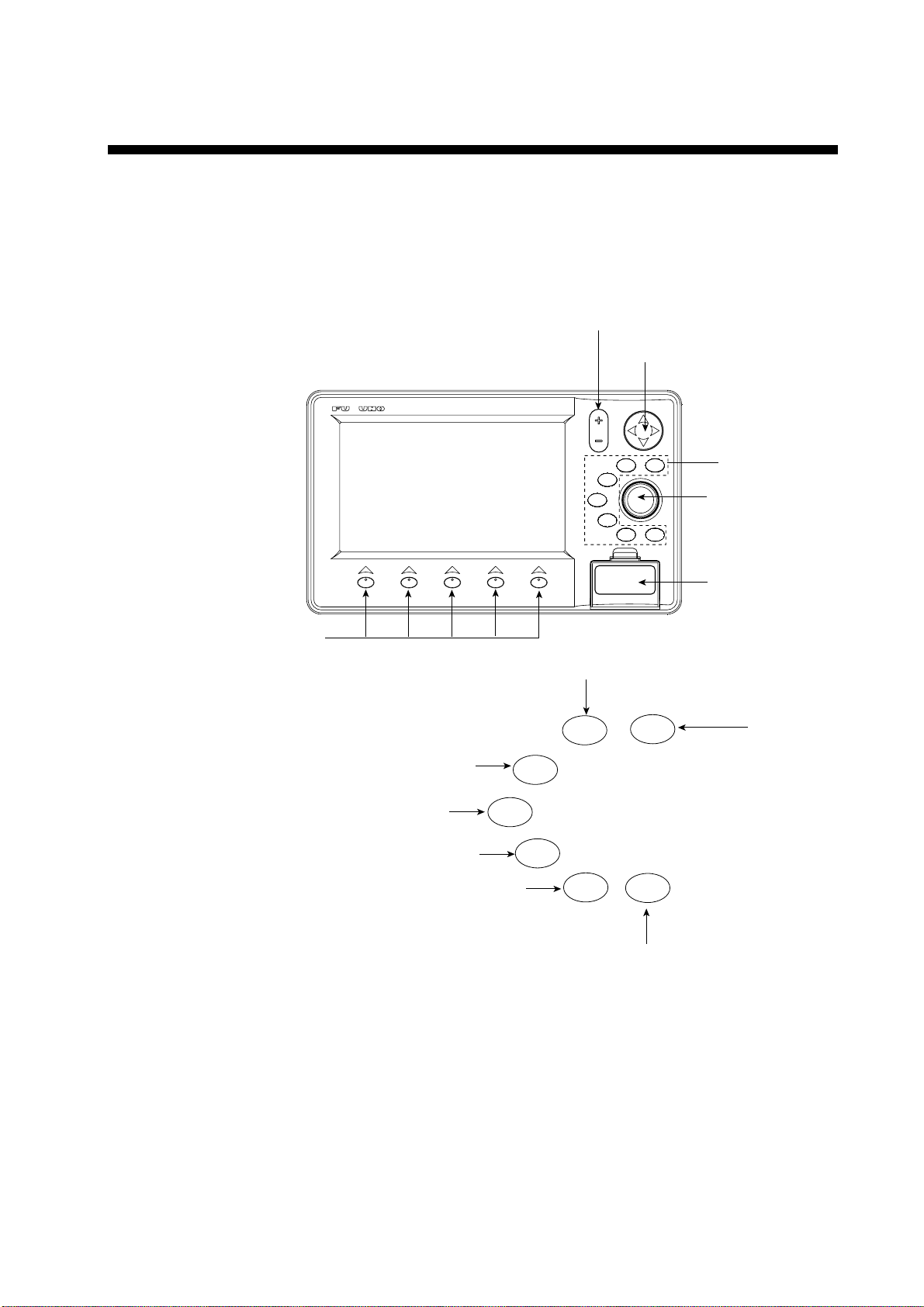
1.1 Display Unit Controls
CLEAR
BRILL
POWER
GOTO
WPT
SAVE
MOB
DISP
TO ENTER
PUSH
MENU
RANGE
Soft keys
Card slot
Cursor pad
RANGE key
ENTER knob
See below.
MENU
DISP
MOB
WPT
TLL
GOTO
ROUTE
CLEAR
POWER
BRILL
Opens the menu.
Opens the DISPLAY MODE menu.
Enters waypoint or MOB mark.
Brief press:
Sets/releases the the destination.
Long press: Outputs the TLL data.
Closes the menu and window.
Silences audible alarms.
Brief press: Turns power on./Shows the brilliance setting window.
Long press: Turns power off.
Shows the route list.
Display unit, front view

1. OPERATIONAL OVERVIEW
1-2
1.2 Loading an SD
TM
Chart Card
Your unit reads C-MAP NT
+
/NT MAX
TM
charts, stored on SD
TM
cards. Insert the
appropriate chart card for your area before turning the power on to show chart
data automatically.
Note 1: Static electricity can be passed through your fingers to a card and
destroy the contents of the card. To prevent this, always touch a metallic
object, such as a steel desk, before handling an SD
TM
card.
Note 2: Do not insert or remove a card while the power is on. This may cause
the equipment to freeze.
1. Push down the lid catch to open the card slot cover.
CLEAR
BRILL
POWER
GOTO
WPT
SAVE
MOB
DISP
TO ENTER
PUSH
MENU
RANGE
Card slot cover
Lid catch
Card slot cover
2. Insert appropriate SD
TM
chart card label side up to any slot.
Inside SD chart card
label side up.
Insert
direction
SD
TM
chart card
3. Press the center of the lid catch to close the card slot cover, to protect the
chart drive. (Keep the slot cover closed at all times.)

1. OPERATIONAL OVERVIEW
1-3
1.3 Turning the Power On/Off
Turning the power on
Press the [POWER/BRILL] key until you hear a click and a beep. When the unit
is turned on, it proceeds in the sequence shown in the figure below.
In about 30 seconds the
last-used display appears.
You can go to the last-used
display faster by pressing any
key when this screen appears.
GP-7000F
GPS PLOTTER SOUNDER
FURUNO ELECTRIC CO., LTD.
STARTUP TEST
PLOTTER
ROM : OK
RAM : OK
BACKUP DATA : OK
INTERNAL BATTERY : OK
INTERNAL GPS : OK
ECHO SOUNDER
ROM : OK
RAM : OK
POWER SETTING : 600 W (or 1 KW)
C-MAP electronic charts (ECs) are derived from
geographical data -including official government
charts - which we believe to be accurate.They are
neither verified nor approved by Hydrographic
Authorities. C-MAP ECs are designed only to ease
and speed navigation calculations and so must not
be relied upon as aprimary source of navigation
information, but rather a backup to the use of
official government charts and prudent navigation
habits.
There is no direct relationship between the color
of water areas and their depth. The navigator shall
always query the area for depth information and use
the official paper charts.
WARNING
Start-up sequence
Note 1: The example screens shown in this manual may not match the screens
you see on your display. The screen you see depends on your system
configuration and equipment settings.
Note 2: If the message “SYSTEM HAS FAILED START UP TEST. PLEASE
CONTACT A LOCAL FURUNO REPRESENTATIVE FOR REPAIR.
PRESS ANY KEY TO CONTINUE.” appears, contact your dealer for
advice.
Note 3: At the very first time you turn on your unit, the simulation mode window
appears. Choose YES or NO as appropriate and push the [ENTER]
knob.
The equipment takes 90 seconds to find its position when turned on for the very
first time. Thereafter it takes about 12 seconds to find position each time the
power is turned on. The message “NO FIX”, which means the equipment is now
finding its position, appears at the bottom of the plotter display immediately after
turning the power on. When the GPS receiver finds its position, “NO FIX”
changes to “2D” or “3D” to show that position data is now accurate.
Turning the power off
Press and hold the [POWER/BRILL] key until the screen goes blank (about four
seconds).

1. OPERATIONAL OVERVIEW
1-4
1.4 Adjusting Brilliance and Contrast
You can adjust display brilliance and contrast as shown below.
1. Press the [POWER/BRILL] key momentarily.
The BACKLIGHT window appears.
BACKLIGHT
ENTER TO SET
Backlight window
2. Rotate the [ENTER] knob to adjust.
Rotate clockwise to raise the setting or counterclockwise to decrease it.
To escape from this window without adjusting, press the [CLEAR] or
[POWER/BRILL] key, or wait three seconds to let the equipment close it
automatically.
3. Press the [ENTER] key to close the window.

1. OPERATIONAL OVERVIEW
1-5
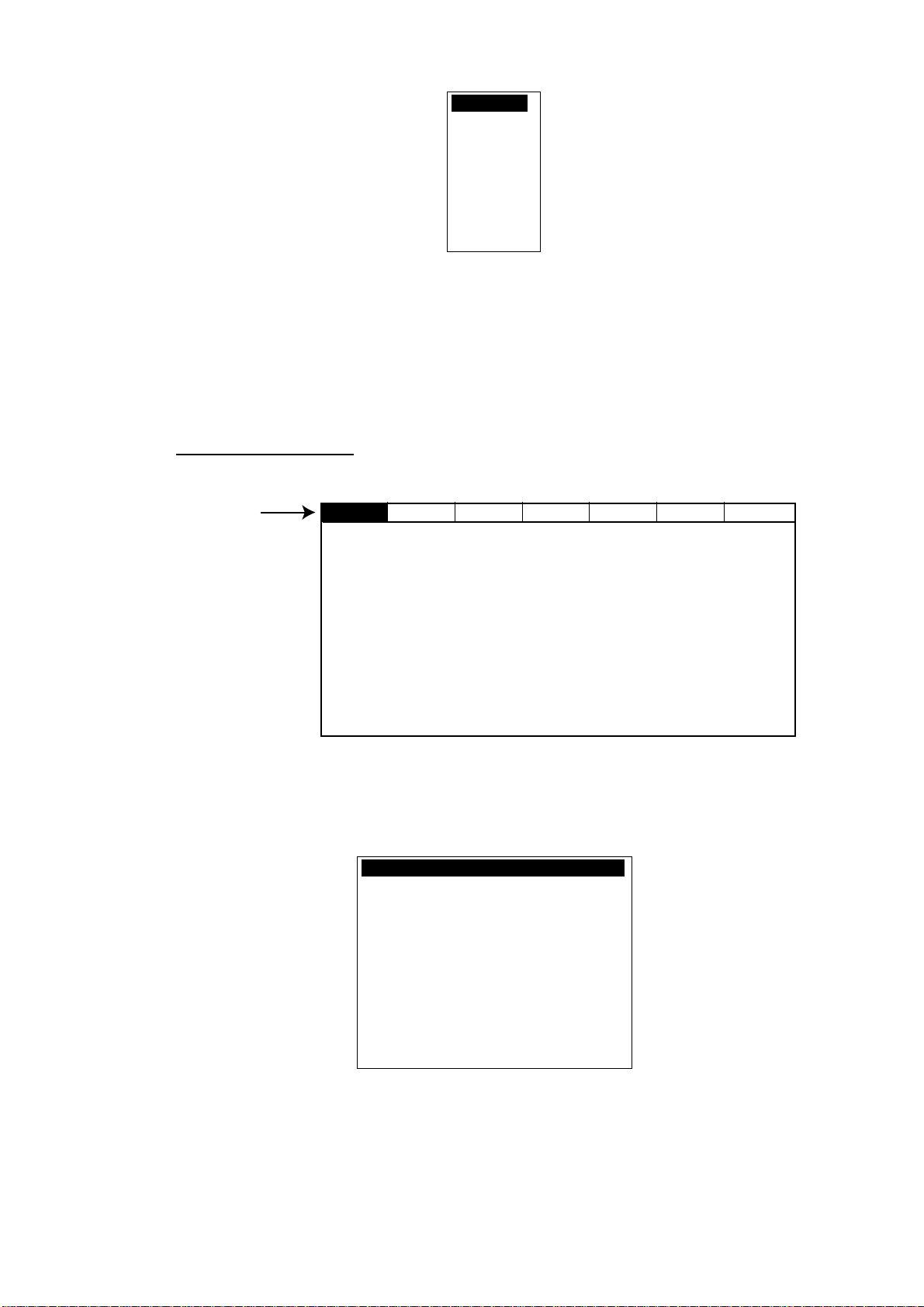
1.5 Selecting a Display
Fourteen screen displays are available as shown figure in below.
1. Press the [DISP] key to show the DISPLAY MODE screen.
DISPLAY MODE
TURN KNOB TO SELECT DISPLAY MODE AND PRESS KNOB TO ENTER.
Display m ode s c r een
2. Use the cursor pad or [ENTER] knob to select a mode.
To escape from the display mode screen without changing the display mode,
press the [DISP] key.
3. Press the [ENTER] knob to set the new display mode.
1.6 Soft Keys
The soft keys, their labels displayed at the bottom of the screen, provide for easy
execution of a desired function, and their label and function change according to
the display in use. When you turn on the power, the soft keys do not appear. To
show the soft keys, press any soft key. To access a soft key function, press the
appropriate soft key within five seconds after accessing them.
Soft keys
The soft keys disappear after five seconds. If you want to erase them earlier,
press the [CLEAR] key.
1. OPERATIONAL OVERVIEW
1-6
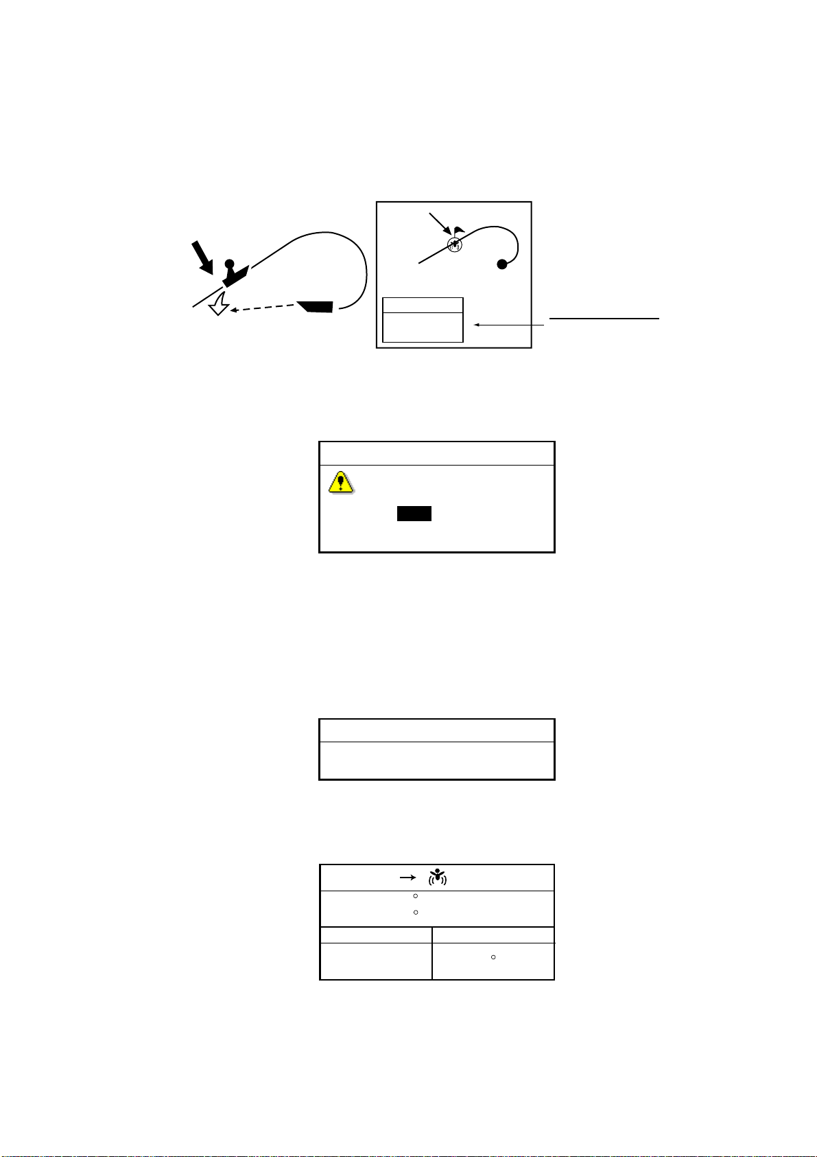
1.7 MOB Mark
1.7.1 Entering the MOB mark, setting MOB as destination
The MOB (Man Overboard) mark functions to mark man overboard position. You
can inscribe this mark from any mode.
Man
overboad
Range, bearing
Current
position
MOB
mark
MOB
MOB
162.5°M
0.49 nm
MOB information
Distance and range
to MOB position
MOB concept
1. Press and hold down the [MOB/WPT] key immediately for about three
seconds when someone falls onboard, to show the display below.
MAN OVER BOARD!
Set (MOB) as destination?
YES NO
MOB message window
2. Confirm that YES is selected, and then press the [ENTER] knob to set the
MOB position as the destination. (Choose NO to mark position as a
waypoint.)
If you select the MOB position as the destination, the MOB ALARM window
appears. Push the [ENTER] knob to erase it and then the following message
appears on the display.
MOB ALARM
MOB function is activated
MOB ALARM window
Distance and bearing to the MOB position are shown in the MOB data box when
the cursor is placed on the MOB mark.
MOB
FIX
DST
BRG
33 07. 674N
132 51. 766W
1.14 nm
187 M
MOB data box

1. OPERATIONAL OVERVIEW
1-7
1.7.2 Deleting the MOB mark
1. Operate the cursor pad to place the cursor on the MOB mark, and then press
the STOP soft key to cancel the navigation to the MOB mark.
2. Press the DELETE soft key to show the confirmation window.
3. Choose “YES”, and then press the [ENTER] knob to delete the MOB mark.
The color of MOB mark changes to blue. After changing the range, the MOB
mark is cleared completely.
1.8 Menu Operation
Most operations are carried out from the menu bar. The menu bar is opened or
closed with the [MENU] key. Menus and options may be selected by rotating the
[ENTER] knob or operating the cursor pad. However, this manual describes
operating procedure using the [ENTER] knob.
Using the [ENTER] knob
1. Press the [MENU] key to show the menu bar.
Menu Bar
GENERAL PLOTTER MAP ALARMS ADVANCED INFO FIND
Menu bar
2. Rotate the [ENTER] knob to choose a menu title and then push the [ENTER]
knob to show the menu.
For example, choose GENERAL to display the GENERAL menu.
LANGUAGE English
KEYPAD BEEP Off
PALETTE Normal
TIME LINE Infinite
TIME REFERENCE UTC
TIME FORMAT 12hour
DATE FORMAT MM-DD-YY
AUTO INFO On All
SHIP ICON
WIND GRAPH True
UNITS OF MEASURE
General menu
3. Rotate the [ENTER] knob to choose an item and then push the [ENTER]
knob.
For example, choose LANGUAGE.
1. OPERATIONAL OVERVIEW
1-8
English
Italiano
Francais
Deutsch
Espanol
Norsk
Svensk
Portuguese
Language option window
4. Rotate the [ENTER] knob to choose the option desired and then press the
[ENTER] knob.
To cancel, press the [CLEAR] key.
5. To close all menus and option windows, press the [MENU] key.
To close option windows one by one, press the [CLEAR] key.
Using the cursor pad
1. Press the [MENU] key to show the menu bar.
Menu Bar
GENERAL PLOTTER MAP ALARMS ADVANCED INFO FIND
Menu bar
2. Press ◄ or ► on the cursor pad to choose a menu title and then press ▼ to
show the corresponding menu.
For example, choose GENERAL to display the GENERAL menu.
LANGUAGE English
KEYPAD BEEP Off
PALETTE Normal
TIME LINE Infinite
TIME REFERENCE UTC
TIME FORMAT 12hour
DATE FORMAT MM-DD-YY
AUTO INFO On All
SHIP ICON
WIND GRAPH True
UNITS OF MEASURE
General menu
3. Press ▼ to choose an item and then press ► to show its option window.
For example, choose LANGUAGE.

1. OPERATIONAL OVERVIEW
1-9
English
Italiano
Francais
Deutsch
Espanol
Norsk
Svensk
Portuguese
Language option window
4. Press ▼ to choose an option and then press ► to close the window.
To cancel, press ◄.
5. To close all menus and option windows, press the [MENU] key.
To close option windows one by one, press the [CLEAR] key.
1.9 Simulation Mode
The simulation mode, which is for use by service technicians for demonstration
purposes, provides simulated operation to help acquaint users with the functions
of the unit. All keys are operative.
“SIMUL” appears at the bottom of the display when the simulation mode is
active.
Plotter
Own ship’s mark moves from the default or selected position at the speed and
course set.
1. Press the [MENU] key to display the menu bar.
2. Rotate the [ENTER] knob to choose ADVANCED and then push the [ENTER]
knob.
3. Rotate the [ENTER] knob to choose GPS SIMULATION and then push the
[ENTER] knob to show the following window.
SIMULATION MODE Off
COURSE 007 M
SPEED 001.0 Kts
DATE Apr/02/04
TIME 12:00:00 AM
CURSOR CONTROL Off
GPS simulation window
4. Rotate the [ENTER] knob to choose SIMULATION MODE and then push the
[ENTER] knob.
5. Rotate the [ENTER] knob to choose On and then push the [ENTER] knob.
6. Rotate the [ENTER] knob to choose COURSE and then push the [ENTER]
knob.
7. Enter the course (Setting range: 0 to 359) by rotating the [ENTER] knob,
pressing the ◄ or ►, and then press the SAVE soft key.

1. OPERATIONAL OVERVIEW
1-10
Note: You can return the value to zero by pressing the CLR FLD soft key.
8. Enter SPEED, DATE and TIME.
9. Rotate the [ENTER] knob to choose CURSOR CONTROL and then push the
[ENTER] knob.
10. Rotate the [ENTER] knob to choose On or Off as appropriate and then push
the [ENTER] knob.
When On is selected, you can set course value (◄ ►) and speed value (▲ ▼)
on the simulation plotter display.
When you select On, the cursor does not appear on the plotter menu.
11. Rotate the [ENTER] knob to choose SELECT POSITION and then push the
[ENTER] knob.
The plotter display appears.
12. Operate the cursor pad to place the cursor at the desired starting point.
13. Push the [ENTER] knob to move the own ship mark on the cursor.
14. Press the [CLEAR] key.
Echo sounder
1. Press the [MENU] key to show the menu bar on the plotter display.
2. Rotate the [ENTER] knob to choose ADVANCE and then push the [ENTER]
knob.
3. Rotate the [ENTER] knob to choose ECHO SOUNDER SIMULATION and
then push the [ENTER] knob.
4. Rotate the [ENTER] knob to choose On and then push the [ENTER] knob.
5. Press the [MENU] key to close the menu.
6. Choose the sounder display on the display mode screen.
2-1
2. PLOTTER DISPLAYS
2.1 Presentation Modes
The plotter display mainly shows chart, ship’s track, waypoints, and navigation
data.
Three types of display presentations are provided for the normal plotter display:
north-up, course-up and auto course-up. To change the mode, use the
presentation mode selection soft key, which is the leftmost soft key.
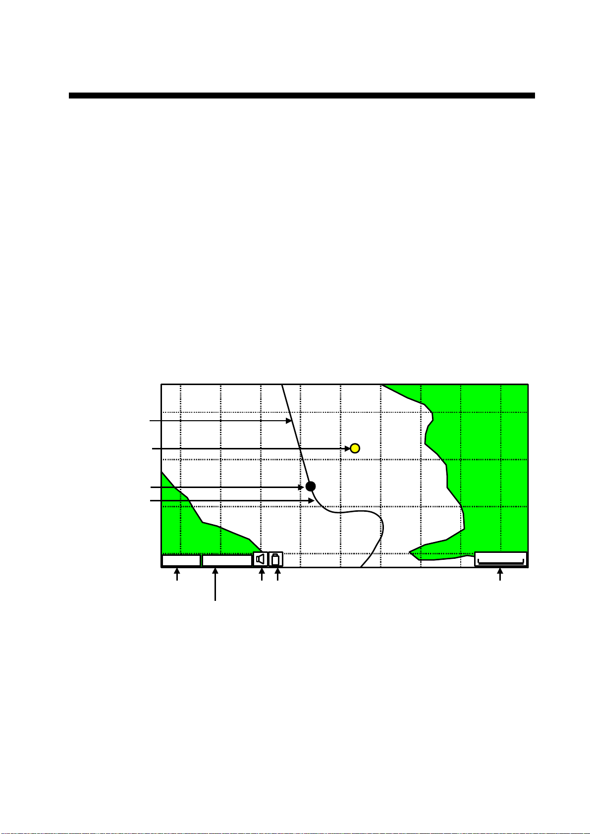
2.1.1 North-up
1. Press any soft key to show the soft key labels.
2. Press the NORTH UP soft key to show the north-up display. North (zero
degree) is at the top of the display.
When the cursor is on, the own ship moves and the chart is fixed. (True motion)
When the cursor is off, the chart, waypoints and other marks move and own ship
is fixed. (Relative motion)
To turn the cursor off, press the CENTER soft key.
0001WPT
GPSW2D
1 nm
Track
GPS status
Current display mode
(north-up)
Icons
Range scale
Waypoint
Course bar
Own ship marker
Plotter display, north-up mode

2. PLOTTER DISPLAY
2-2
2.1.2 Course-up
Press the COURSE UP soft key to show the course-up display. When
destination is set, it is at the top of the screen and the north mark appears at the
upper right side of the screen and points to north.
When destination is not set, the course is upward on the screen at the moment
the course-up mode is selected.
0001WP
1
nm
COURSE UP CENTER
MAP SETUP
SEARCH
N
NAV DATA
Plotter display, course-up mode
2.1.3 Auto course-up
Press the AUTO CSE UP soft key to show the automatic course-up display. The
course or heading is at the top of screen at the moment the auto course-up
mode is selected. When own ship is off its intended course by 30º (default
setting, this degree can be changed on NAVIGATION menu. For details, see
chapter 8.) or more, it is automatically brought back to perpendicular.
0001WP
1 nm
AUTO CSE UP CENTER
MAP SETUP
N
SEARCH
NAV DATA
Plotter display, auto course-up mode

2. PLOTTER DISPLAY
2-3
2.2 Cursor
2.2.1 Turning on the cursor, shifting the cursor
Press the cursor pad to turn the cursor on, and the cursor appears at the own
ship’s position. Operate the cursor pad to shift the cursor. The cursor moves in
the direction of the arrow or diagonal pressed on the cursor pad.
Cursor state determines what data is shown in the NAVDATA window. This
window can be enabled or disabled by pressing the NAVDATA ON soft key.
NAVDATA window
Also, when the cursor is placed on own ship’s position, its data is shown as
follows.
FIX 3D
SOG COG
33 37.125N
118 48.428W
1.00 kts 007 M
Own ship’s position data window
2.2.2 Moving the cursor to the center of the screen
Press the CENTER soft key to return the cursor to the screen center.
2. PLOTTER DISPLAY
2-4
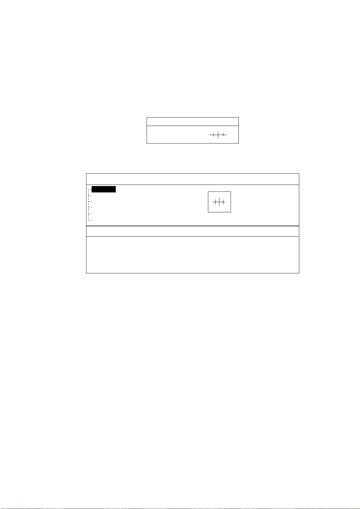
2.2.3 Displaying data
Besides its fundamental functions of providing position data, the cursor can also
provide data for chosen caution area, depth area, source of data, etc. Further,
you can display information about an icon by placing the cursor on it.
1. Press the cursor pad to turn the cursor on.
2. Use the cursor pad to place the cursor on the position desired.
The object information window appears.
Object Info
Wreck
Object information window (ex. wreck)
3. If you want to know more details, press the Details soft key.
Objects
Wreck
Category of wreck
non-dangerous wreck
Water level effect
always under water/submerged
Wreck
Caution area
Depth area
Military practice area
Sea area
Source of data
Object detail window (ex. wreck)
4. Rotate the [ENTER] knob to choose the item you want to know more about.
Detailed information appears in the lower column.
5. Press the [CLEAR] key to close the window.
2.3 Selecting Chart Scale/Range
Chart scale (range) may be selected with the [RANGE] key. The [RANGE +] key
zooms in the chart; [RANGE -] key zooms out it.
2. PLOTTER DISPLAY
2-5
2.4 Navigation Data Display
The navigation data display provides generic navigation data, and it is shown in
combination displays.
Appropriate sensors are required. Bars (- -) appear when corresponding sensor
is not connected.
LATITUDE
22º
03
.7
30
N
LONGITUDE
1
3
7º
5
7.
8
7
0
E
SOG
S
COG
º
TRIP
TEMP
º
TIME
12:2
8
AM
DATE
Apr/17/04
DEPTH
Position
Trip meter
Speed
Course
Depth
Temperature
Navigation data display
Changing the information displayed
1. Press and hold the [MENU] key down for two seconds to show Speed in
reverse video.
2. Rotate the [ENTER] knob to show data in reverse video.
3. Press the [ENTER] knob to show the selection window as shown below.
SOG
COG
STW
HDG
DST
BRG
TRIP
DEPTH
TEMP
HDOP
VDOP
XTE
DRF
SET
WST
WDT
WSA
WDA
DATE
TIME
TTG
ETA
DEST
Note: Contents may be changed
depending on data selected at step2.
4. Rotate the [ENTER] knob to choose the data to show, and then press it.
The item window (ex. units) appears.
5. Rotate [ENTER] knob to select the unit.
The data selected at step 2 changes to your selection.
6. Press the [CLEAR] key to erase the reverse video.
2. PLOTTER DISPLAY
2-6
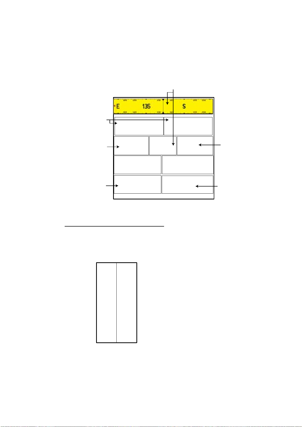
2.5 Compass Display
The compass display, shown in combination displays, provides steering
information. The compass rose shows two triangles: the red triangle shows own
ship’s course and the black triangle, which moves with ship’s course, shows the
bearing to destination waypoint.
The water temperature and depth graphs, which require appropriate sensors,
shows the latest 10 minutes of water temperature and depth data.
DEST:
0001WP
DST*
305.3
nm
SOG*
12.0
Kts
TTG:25:26
ETA:12:28AM
DPT
45.6ft
TMP
40.4ºF
155º
STW*
12.4
KTS
N
w
E
Ship's course
(red)
Water temperature
graph**
Shown (in green)
when direction to
steer is "right."
XTE monitor
(See below for
description.)
Shown (in red)
when direstion to
steer is "left".
Depth
graph**
Destination
waypoint
bearing
(black)
Time-to-go
to destination
Own ship marker
(Yellow)
Destination
waypoint
Speed
through
water
Range to destination waypoint
Speed over ground
Bearing scale
Estimated time of
arrival at destination
0.5 0.5
**: Appropriate sensor is required.
Compass distance
Reading t he XTE (cross-track error) mon itor
The XTE monitor, located below the compass rose, shows the distance you are
off course and the direction to steer to return to course. The own ship marker in
the monitor moves according to direction and distance off course. An arrow
appears at the right or left side of the XTE monitor and it shows the direction to
steer to return to intended course. It is shown in red when you should steer left,
and green when you should steer right. In the example above you would steer
left to return to course. To maintain course, steer the vessel so the own ship
marker stays at the center of the XTE monitor. Note that the XTE range can be
changed by rotating the [ENTER] knob.
Nav dat a
Data marked with * in above can be changed to display. See page 2-5.

2. PLOTTER DISPLAY
2-7
2.6 Highway Display
The highway display, shown in combination display with the plotter screen,
provides a graphic presentation of ship’s track along intended course. It is useful
for monitoring ship’s progress toward a waypoint. The own ship marker shows
the relation between your vessel and intended course.
TIME*
12:28AM
SOG*
12.0KTs
COG*
044º
Turn knob to change scale: 0.2nm
Course
Speed
Current time
Own ship marker
Intended course
Destination waypoint
(Flag)
Bearing of
destination
waypoint
Highway display
Changing the scale
You can change the scale of the highway display to 0.2, 0.5, 1.0, 2.0, 4.0 or 10.0
(nm). Rotate the [ENTER] knob to change it. Note that the available range
depends on own ship’s position.
Nav dat a
Data marked with * in above can be changed to display. See page 2-5.
2. PLOTTER DISPLAY
2-8
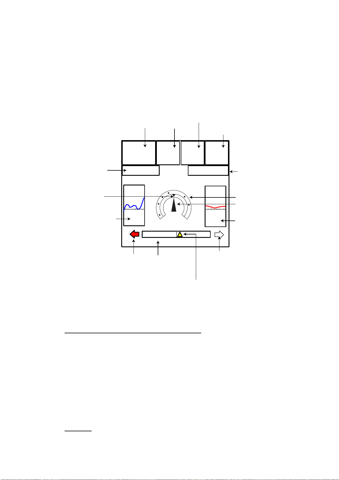
2.7 GPS Status Display
The GPS status display provides data on the GPS satellites.
33 18.426N
12:09 AM
1.00
Apr/02/04
ACQUIRING
LONGITUDE
LATITUDE
HDOP
SOG Kts
DATE
TIME
131 48.608W
12.5
07 14 25 31 -- --
01 11 20 28 -- --
07
01
11
14
25
31
28
Position
DOP value
Receive signal level:
Bars show satellite
signal level. Satellites
in brown are used in
fixing position.
Estimated position in the sky,
and satellite number in brown circle
is used for positioning.
GPS status display
2. PLOTTER DISPLAY
2-9
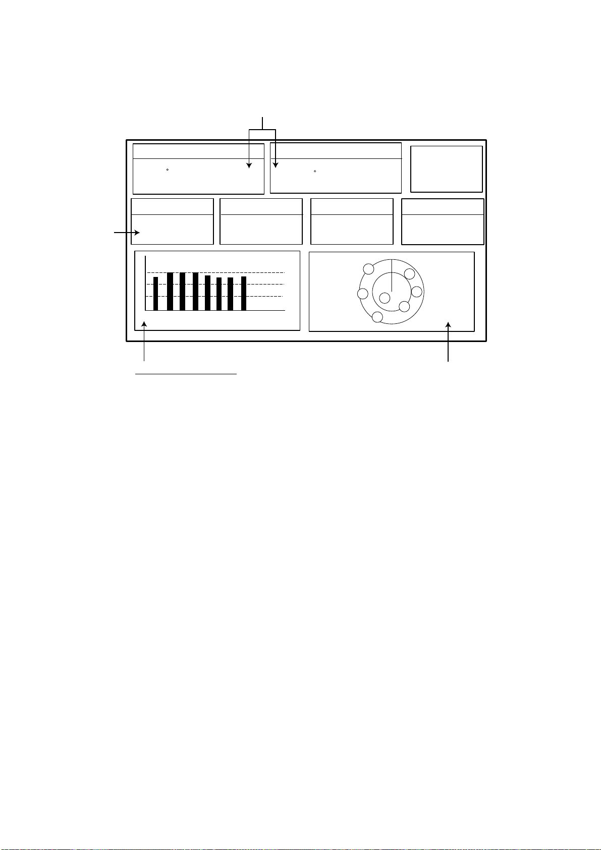
2.8 Celestial Display
Your plotter provides for calculation of the tide heights for any date. Additionally it
displays the time of sunrise, sunset, moonrise and moonset.
ENTER to change Date - Turn the KNOB to set [DLS/STANDARD] time
Nearest Tide Station:
High Water
Low Water
From tide
Sunrise:
Sunset:
Moonrise:
Moonset:
Date
Time
- - - - -
- - - - -
- -.- - nm
03:50 PM U
01:49 AM U
10:29 AM U
10:07 PM U
- . - - ft
- . - - ft
- - - M
Moon phase
50%
33 20. 435N
131 48.608W
April-01-2004
02:35
Tide, celestial display
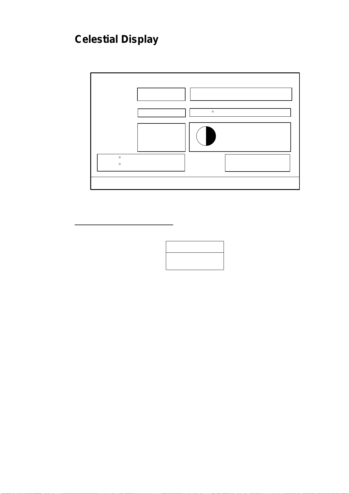
Setting the date for calculation
1. Press the [ENTER] knob to show the date window.
MM-DD-YY
04/09/04
Date window
2. Press the cursor pad to move the cursor, and then rotate the [ENTER] knob
to choose the date.
When you want to clear all values, press the CLR FLD soft key.
To escape, press the CANCEL soft key.
3. Press the SAVE soft key to set.
Tide, Celestial Display
2. PLOTTER DISPLAY
2-10
2.9 Graph Display
Four graphs can be displayed alternately on the half-screen of the LCD: depth,
wind, water temperature and SOG (speed).
Press the GRAPH TYPE soft key to choose display graphs in the sequence
shown below.
Note: Appropriate sensors required to display graphs.
Depth Graph Page 1 of 4
40.2
30.2
20.2
10.2
03:33
03:34 03:35
Depth graph
Wind Graph Page 2 of 4
1.2
2.2
3.2
4.2
03:33
03:34 03:35
Wind graph
Water Temp. Graph Page 3 of 4
66.2
67.2
68.2
69.2
03:33
03:34 03:35
Water temperature graph
SOG Graph Page 4 of 4
0.5
0.7
1.0
1.2
03:33
03:34 03:35
SOG graph
1.0 kts
9.6 Ft
3.1 knot
67.4 F
GRAPH TYPE
soft key
GRAPH TYPE
soft key
GRAPH TYPE
soft key
GRAPH TYPE
soft key
Sequence of graph display
 Loading...