


 Loading...
Back
COLOR GPS/PLOTTER
GP-3500
9-52 Ashihara-cho,
Nishinomiya 662-8580, JAPAN
Telephone : |
0798-65-2111 |
|
Fax |
: |
0798-65-4200 |
All rights reserved. |
Printed in Japan |
Pub. No. OME-44210
( TATA ) GP-3500
The paper used in this manual is elemental chlorine free.
Your Local Agent/Dealer
FIRST EDITION : JUL. 2003
F4 : APR. 13, 2005
*00014677602*
*00014677602*
* 0 0 0 1 4 6 7 7 6 0 2 *
*OME44210F40*
*OME44210F40*
* O M E 4 4 2 1 0 F 4 0 *

 SAFETY INSTRUCTIONS
 WARNING
ELECTRICAL SHOCK HAZARD
Do not open the equipment.
Only qualified personnel should work inside the equipment.
Do not disassemble or modify the equipment.
Fire, electrical shock or serious injury can result.
Immediately turn off the power at the switchboard if the equipment is emitting smoke or fire.
Continued use of the equipment can cause fire or electrical shock. Contact a FURUNO agent for service.
Keep heater away from equipment.
A heater can melt the equipment's power cord, which can cause fire or electrical shock.
Do not operate the unit with wet hands.
Erectlic shock can result.
About the TFT LCD
The TFT LCD is constructed using the latest LCD techniques, and displays 99.99% of its pixels. The remaining 0.01% of the pixels may drop out or blink, however this is not an indication of malfunction.
 CAUTION
No one navigation device should ever be solely replied upon for the navigation of
a vessel.
Always confirm position against all available aids to navigation, for safety of vessel and crew.
Use the proper fuse.
Fuse rating is shown on the power cable. Use of a wrong fuse can result in damage to the equipment.
No single navigation aid should even be relied upon as the exclusive means for navigating your vessel.
The navigator is responsible for checking all aids (including nautical charts) available to confirm his position. Electronic aids are intended to assist, not replace, the navigator.
Do not use the equipment for other than its intended purpose.
WARNING LABEL
A warning label is attached to the equipment. Do not remove the label. If the label is missing or damaged, contact
a FURUNO agent or dealer about replacement.
WARNING |
Name: Warning Label (1) |
|
Type: 86-003-1011-1 |
||
To avoid electrical shock, do not |
||
remove cover. No user-serviceable |
Code No.: 100-236-231 |
|
parts inside. |
|
i

FOREWORD
Congratulation on your choice of the FURUNO GPS COLOR PLOTTER GP-3500. For over 50 years FURUNO Electric Company has enjoyed an enviable reputation for innovative and dependable marine electronics equipment. This dedication to excellence is furthered by our extensive global network of agents and dealers.
The equipment is designed and constructed to meet the rigorous demands of the marine environment. However, no machine can perform its intended function unless installed, operated and maintained properly. Please carefully read and follow the recommended procedures for operation and maintenance.
Feature
The GP-3500 consists of the display unit and antenna unit. The display unit is totally integrated GPS receiver and color video plotter.
The GPS receiver tracks up to thirteen satellites (GPS: 12, WAAS: 1) simultaneously, and an 8-state Kalman filter ensures optimum accuracy in determination of vessel position, course and speed.
Main features of the GP-3500
•Bright 10.4-inch color TFT LCD with temperature compensated tone and brilliance control
•Simplified operation using individual keys, ENTER knob and trackball
•Three lines, main and sub of own ship’s track, and other ship’s track can be displayed simultaneously.
•Accepts FURUNO and NavCharts (NAVIONICS) charts, or C-MAP NT charts (C-MAP), depending on specification. All names mentioned are registered trademarks of their respective companies.
•Fast chart redraw.
•Built-in backup memory stores 80,000 points total of own ship’s tracks and marks
•Stores 3500 waypoints and 200 routes with up to 35 waypoints.
•Man overboard feature records latitude and longitude coordinates at time of man overboard.
•Alarms: Arrival, Anchor Watch, Cross-track Error, Proximity, Speed, Trip, Temperature, Current and Depth.
•User programmable PROG key
•Own ship and cursor positions may be shown in latitude and longitude, Loran A, Loran C or Decca LOPs.
•Data storage on memory cards.
•Improved position accuracy with optional DGPS beacon receiver.
ii
TABLE OF CONTENTS
|
|
|
|
............................................................................SYSTEM CONFIGURATIONS |
vii |
||
1. BASIC OPERATION ...................................................................................... |
1-1 |
||
1.1 |
Controls Description .................................................................................................. |
1-1 |
|
|
1.1.1 |
Display unit ..................................................................................................... |
1-1 |
|
1.1.2 |
Remote controller............................................................................................ |
1-2 |
1.2 |
Loading a Mini Chart Card ......................................................................................... |
1-3 |
|
1.3 |
Turning the Power On/Off .......................................................................................... |
1-4 |
|
1.4 |
Adjusting Brilliance and Hue ...................................................................................... |
1-6 |
|
|
1.4.1 |
Adjusting display brilliance .............................................................................. |
1-6 |
|
1.4.2 Adjusting control panel dimmer ....................................................................... |
1-7 |
|
|
1.4.3 |
Selecting hue .................................................................................................. |
1-9 |
1.5 |
Selecting a Display .................................................................................................. |
1-10 |
|
1.6 |
MOB Mark ............................................................................................................... |
1-11 |
|
1.7 |
Using PROG Key..................................................................................................... |
1-12 |
|
1.8 |
Simulation Mode...................................................................................................... |
1-13 |
|
1.9 |
Menu Overview........................................................................................................ |
1-15 |
|
2. PLOTTER AND PILOT DISPLAY DESCRIPTION......................................... |
2-1 |
||
2.1 |
Plotter and Pilot Displays ........................................................................................... |
2-1 |
|
|
2.1.1 |
Plotter display.................................................................................................. |
2-1 |
|
2.1.2 |
Pilot display..................................................................................................... |
2-2 |
|
2.1.3 NAV INFO 1 display ........................................................................................ |
2-3 |
|
|
2.1.4 Compass plotter (or pilot) display .................................................................... |
2-4 |
|
|
2.1.5 |
GPS status display .......................................................................................... |
2-6 |
2.2 |
Operating the Cursor ................................................................................................. |
2-7 |
|
2.3 |
Shifting the Display .................................................................................................... |
2-8 |
|
2.4 |
Changing Chart Scale................................................................................................ |
2-8 |
|
2.5 |
Measuring Range and Bearing Between two Points .................................................. |
2-9 |
|
2.6 |
Using the VRM (Variable Range Marker) ................................................................. |
2-11 |
|
2.7 |
Mini Chart Cards...................................................................................................... |
2-12 |
|
3. TRACK ........................................................................................................... |
|
3-1 |
|
3.1 |
Displaying Track ........................................................................................................ |
3-1 |
|
|
3.1.1 |
Own ship’s track.............................................................................................. |
3-1 |
|
3.1.2 |
Sub track......................................................................................................... |
3-3 |
|
3.1.3 |
Other ship’s track ............................................................................................ |
3-4 |
3.2 |
Stopping, Restarting Plotting of Own Ship Track........................................................ |
3-5 |
|
|
3.2.1 Displaying own ship’s track while track plotting is stopped .............................. |
3-6 |
|
|
3.2.2 Connecting own ship’s track when resuming plotting....................................... |
3-7 |
|
3.3 |
Changing Track Color ................................................................................................ |
3-8 |
|
|
3.3.1 Changing own ship’s track color ...................................................................... |
3-8 |
|
|
3.3.2 Changing sub track color................................................................................. |
3-8 |
|
|
3.3.3 Changing target track color ............................................................................. |
3-8 |
|
iii
|
3.3.3 Changing target track color ............................................................................. |
3-8 |
|
|
3.3.4 Automatically changing own ship’s track color by water temperature .............. |
3-9 |
|
|
3.3.5 Changing own ship’s track color according to depth....................................... |
3-11 |
|
3.4 |
Changing Track Line Type....................................................................................... |
3-13 |
|
3.5 |
Track Plotting Method, Interval ................................................................................ |
3-13 |
|
|
3.5.1 |
Track plotting method.................................................................................... |
3-13 |
|
3.5.2 |
Track plotting interval.................................................................................... |
3-14 |
3.6 |
Erasing Tracks ........................................................................................................ |
3-15 |
|
|
3.6.1 Erasing tracks by color.................................................................................. |
3-15 |
|
|
3.6.2 Erasing tracks by line type ............................................................................ |
3-18 |
|
3.7 |
Editing Tracks.......................................................................................................... |
3-19 |
|
3.8 |
Changing Track Memory Capacity........................................................................... |
3-20 |
|
4. MARKS & LINES ........................................................................................... |
4-1 |
|
4.1 |
Entering Marks .......................................................................................................... |
4-1 |
4.2 |
Changing Mark Color ................................................................................................ |
4-3 |
4.3 |
Changing Mark Size.................................................................................................. |
4-4 |
4.4 |
Entering Lines ........................................................................................................... |
4-5 |
4.5 |
Selecting Line Type ................................................................................................... |
4-5 |
4.6 |
Erasing Marks, Lines................................................................................................. |
4-6 |
4.7 |
Editing Marks, Lines.................................................................................................. |
4-9 |
4.8 |
Displaying Mark Data .............................................................................................. |
4-10 |
4.9 |
Target Mark (TLL).................................................................................................... |
4-10 |
5. WAYPOINT..................................................................................................... |
5-1 |
|
5.1 |
Entering Waypoints ................................................................................................... |
5-1 |
|
5.1.1 Entering waypoints at own ship’s position ....................................................... |
5-1 |
|
5.1.2 Entering waypoints by the cursor .................................................................... |
5-2 |
|
5.1.3 Entering waypoints by latitude and longitude position ..................................... |
5-3 |
|
5.1.4 Entering waypoints by range and bearing ....................................................... |
5-6 |
|
5.1.5 Entering waypoints by Loran A or Loran C LOPs............................................. |
5-7 |
|
5.1.6 Entering waypoints by Decca LOPs ................................................................ |
5-8 |
5.2 |
Editing Waypoint Data ............................................................................................... |
5-9 |
5.3 |
Erasing Individual Waypoints................................................................................... |
5-10 |
5.4 |
Searching Waypoints................................................................................................ |
5-11 |
5.5 |
Setting Ship’s Speed for TTG .................................................................................. |
5-12 |
5.6 |
Displaying Waypoint Data........................................................................................ |
5-13 |
5.7 |
Changing Waypoint Mark Size (NAVchart TM/FURUNO only)................................... |
5-14 |
6. ROUTE .......................................................................................................... |
|
6-1 |
|
6.1 |
Entering Routes ........................................................................................................ |
6-1 |
|
|
6.1.1 Entering routes using existing waypoints ........................................................ |
6-1 |
|
|
6.1.2 |
Creating track-based routes............................................................................ |
6-4 |
6.2 |
Editing Routes........................................................................................................... |
6-5 |
|
|
6.2.1 |
Inserting waypoints ......................................................................................... |
6-5 |
|
6.2.2 |
Removing waypoints from routes.................................................................... |
6-5 |
6.3 |
Erasing Routes.......................................................................................................... |
6-6 |
|
6.4 |
Setting Ship’s Speed for TTG .................................................................................... |
6-6 |
|
iv
7. NAVIGATION.................................................................................................. |
7-1 |
|
7.1 |
Navigating to Quick Points......................................................................................... |
7-1 |
7.2 |
Navigating to a Waypoint ........................................................................................... |
7-7 |
7.3 |
Following a Route.................................................................................................... |
7-10 |
7.4 |
Canceling Navigation............................................................................................... |
7-12 |
8. ALARMS ........................................................................................................ |
8-1 |
|
8.1 |
Audio Alarm On/Off.................................................................................................... |
8-2 |
8.2 |
Arrival Alarm/Anchor Watch Alarm ............................................................................. |
8-3 |
8.3 |
XTE (Cross Track Error) Alarm/Border Alarm............................................................. |
8-4 |
8.4 |
Proximity Alarm.......................................................................................................... |
8-5 |
8.5 |
Speed Alarm .............................................................................................................. |
8-6 |
8.6 |
Trip Log Alarm ........................................................................................................... |
8-6 |
8.7 |
Temperature Alarm .................................................................................................... |
8-7 |
8.8 |
Shear Alarm............................................................................................................... |
8-7 |
8.9 |
Bottom Alarm ............................................................................................................. |
8-8 |
9. CUSTOMIZING YOUR UNIT.......................................................................... |
9-1 |
||
9.1 |
CHART SETUP Menu................................................................................................ |
9-1 |
|
|
9.1.1 |
Offsetting the chart .......................................................................................... |
9-1 |
|
9.1.2 CHART SETUP menu items description.......................................................... |
9-4 |
|
|
9.1.3 CONTOUR LINES SETUP menu .................................................................... |
9-7 |
|
9.2 |
PLOTTER SETUP Menu ........................................................................................... |
9-8 |
|
|
9.2.1 |
Setting TD display ........................................................................................... |
9-8 |
|
9.2.2 |
Resetting trip distance................................................................................... |
9-10 |
|
9.2.3 Selecting range of PLOTTER (PILOT) display............................................... |
9-10 |
|
9.3 |
DISPLAY SETUP Menu ........................................................................................... |
9-12 |
|
9.4 |
NAVIGATOR SETUP Menu ..................................................................................... |
9-17 |
|
9.5 |
PROGRAMMABLE KEYS & REMOTE CONTROLLER SETUP Menu..................... |
9-22 |
|
|
9.5.1 |
Programmable key setup............................................................................... |
9-22 |
|
9.5.2 Remote controller (option) setup ................................................................... |
9-25 |
|
9.6 |
DISPLAY MODES & NAV DATA WINDOW SETUP Menu........................................ |
9-27 |
|
|
9.6.1 Setting the DISPLAY MODE screen .............................................................. |
9-27 |
|
|
9.6.2 Setting the navigation data window ............................................................... |
9-30 |
|
9.7 |
I/O PORT SETUP Menu .......................................................................................... |
9-34 |
|
9.8 |
TEST & MEMORY CLEAR Menu............................................................................. |
9-37 |
|
|
9.8.1 |
Setting the password..................................................................................... |
9-37 |
|
9.8.2 |
Removing the password................................................................................ |
9-38 |
10. RECORDING & PLAYING BACK DATA ................................................... |
10-1 |
|
10.1 |
Recording Data........................................................................................................ |
10-1 |
10.2 |
Memory Card Operation .......................................................................................... |
10-2 |
|
10.2.1 Formatting the memory card ......................................................................... |
10-2 |
|
10.2.2 Saving data to a memory card....................................................................... |
10-4 |
|
10.2.3 Displaying data from a memory card ............................................................. |
10-6 |
|
10.2.4 Playing back data from a memory card ......................................................... |
10-7 |
|
10.2.5 Deleting files.................................................................................................. |
10-8 |
v
10.3 |
Automatic Backup Function...................................................................................... |
10-9 |
|
10.3.1 Backup to a memory card .............................................................................. |
10-9 |
|
10.3.2 Backup to internal memory .......................................................................... |
10-10 |
10.4 |
Internal Memory ..................................................................................................... |
10-11 |
|
10.4.1 Saving data to internal memory.................................................................... |
10-11 |
|
10.4.2 Displaying tracks and marks stored in the internal memory.......................... |
10-12 |
|
10.4.3 Playing back data from the internal memory ................................................ |
10-14 |
10.5 Uploading, Downloading Data ................................................................................ |
10-15 |
|
|
10.5.1 Downloading data ........................................................................................ |
10-15 |
|
10.5.2 Uploading data............................................................................................. |
10-17 |
11. MAINTENANCE & TROUBLESHOOTING |
................................................ 11-1 |
|
11.1 |
Maintenance............................................................................................................. |
11-1 |
11.2 |
Replacement of Fuse ............................................................................................... |
11-2 |
11.3 |
Replacement of Battery............................................................................................ |
11-2 |
11.4 |
Trackball Maintenance ............................................................................................. |
11-3 |
11.5 |
Simple Troubleshooting............................................................................................ |
11-4 |
11.6 |
Diagnostics .............................................................................................................. |
11-5 |
|
11.6.1 Memory I/O test ............................................................................................. |
11-5 |
|
11.6.2 Keyboard test................................................................................................. |
11-7 |
|
11.6.3 Test pattern.................................................................................................... |
11-8 |
11.7 |
Clearing the Working Memory .................................................................................. |
11-9 |
11.8 |
Cold Start ............................................................................................................... |
11-10 |
MENU TREE.................................................................................................... |
AP-1 |
|
WORLD TIME CHART.................................................................................... |
AP-6 |
|
GEODETIC CHART LIST ............................................................................... |
AP-7 |
|
ICONS |
............................................................................................................. |
AP-8 |
WHAT IS WAAS?............................................................................................ |
AP-9 |
|
SPECIFICATIONS........................................................................................... |
SP-1 |
|
DECLARATION OF CONFORMITY |
|
|
vi
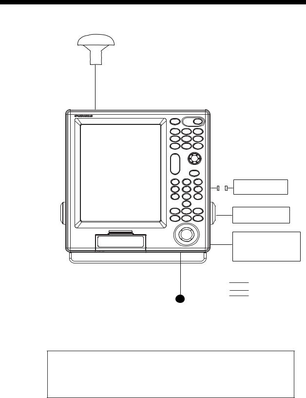
SYSTEM CONFIGURATIONS
GPA-017S/GPA-019S* (option)
Display unit
GP-3500
External monitor
Remote controller
External equipment (Autopilot, radar, etc.)
: Standard supply : Option
: User supply
12-24 VDC
*: Only when the optional beacon receiver kit is installed.
This GPS receiver complies with Canadian standard RSS-210 (Low Power License-Exempt Radio communication Devices).
Operation is subject to the following two conditions:
(1)this device may not cause interference, and
(2)this device must accept any interference, including interference that may cause undesired operation of the device.
vii
This page is intentionally left blank.
viii

1.BASIC OPERATION
1.1Controls Description
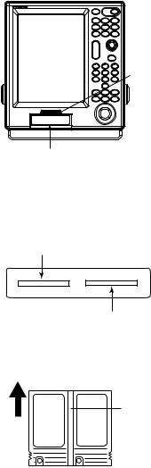
1.1.1Display unit
When you correctly execute an operation, the unit generates a beep. Invalid operation causes the unit to emit three beeps.
|
Card slot |
|
|
|
|
|
Opens the BRILLIANCE |
|
|
|
|
||
window. |
|
|
|
|
|
|
Momentary press: Registers |
|
|
|
Turns power on/off. |
||
|
own ship's |
|
|
|
|
|
|
positions. |
BRILL |
|
POWER |
Opens the SAVE WPT window. |
|
Long press: Marks man |
|
|
|
|
||
(more than |
overboard |
MOB |
WPT |
GOTO |
Sets/releases the destination. |
|
3 seconds) |
position. |
|
||||
|
|
SAVE |
|
|
|
|
Displays the DISPLAY MODE |
DISP |
PROG1 |
MENU |
|
||
screen. |
|
|
||||
|
|
|
|
|
||
|
|
PROG2 |
PROG3 |
PROG4 |
Executes program assigned. |
|
|
|
ZOOM |
|
|
ENTER knob |
|
|
|
|
|
Push: Registers numeric data |
||
|
|
IN |
|
|
||
Enlarges/shrinks display. |
|
|
or operation. |
|||
ZOOM |
|
|
||||
|
|
|
|
Rotate: Selects menu items. |
||
|
|
OUT |
|
|
||
|
|
|
|
• Silences the alarm. |
||
|
|
|
|
CLEAR |
||
• Enters numeric data. |
|
|
|
• Erases marks and waypoints. |
||
1 |
2 |
3 |
• Clears alpnanumeric data. |
|||
• Enters mark. |
|
|||||
|
|
|
|
|||
• Selects menu item. |
4 |
5 |
6 |
|
||
|
|
7 |
T 8 |
D 9 |
Mesures the bearing and range |
|
Opens the CHANGE MARK |
|
|
|
between two points. |
||
|
0 |
|
Opens the CHANGE SHIP'S |
|||
COLOR window. |
|
|
|
|||
MARK |
VRM |
TRACK |
TRACK COLOR window. |
|||
|
|
|||||
|
|
COLOR |
|
COLOR |
Shows the VRM. |
|
• Displays/erases the cursor. |
CURSOR |
|
PLOT |
|||
CENTER |
|
|||||
• Switches + to - and vice vevsa. |
ON/OFF |
|
INTVL |
Changes the track plotting method |
||
|
|
|
||||
• Switches N to S, E to W and |
|
|
|
and plotting interval. |
||
vice vevsa. |
|
|
|
|
Trackball |
|
Moves own ship's position |
|
|
|
|||
|
|
|
• Moves the cursor. |
|||
or cursor position to center. |
|
|
|
|||
|
|
|
• Selects the menu item. |
|||
|
|
|
|
|
||
Control panel
1-1
1. BASIC OPERATION
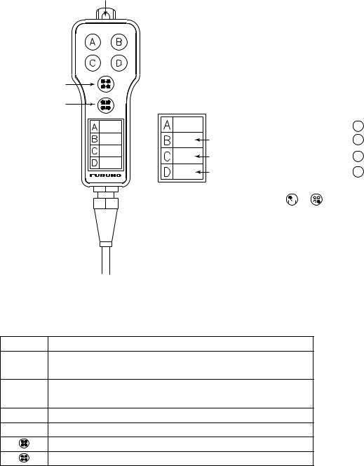
1.1.2Remote controller
The remote controller provides for armchair control of the display unit. It has six keys, all of which may be programmed by the user.
Hole for hooking.
ZOOM IN |
|
ZOOM OUT |
Label |
 Record the function registered to A key.
Record the function registered to B key.
Record the function registered to C key.
Record the function registered to D key.
Note: When proqramming the  or
or  key, make a mental note of their programs, as there is no space on the remote confroller for recordings its program.
Remote controller
The default key functions are as below.
Key Function
AEnter a waypoint with the next consecutive waypoint number at the own ship (or cursor) position.
BSame as pressing the [ENTER] knob on the control panel.
CSame as [CLEAR] key function.
DSame as [1] key function.
Same as [ZOOM IN] key function.
Same as [ZOOM OUT] key function.
For how to program the remote controller, see paragraph 9.5.2.You can program other function to each key (See paragraph 9.5.2.) Record the function name on the label on the remote controller, using an oil-based felt-tip pen.
1-2
1. BASIC OPERATION
1.2Loading a Mini Chart Card
Your unit reads FURUNO and NavCharts (NAVIONICS) chart cards, or C-MAP chart cards, depending on the type of display unit you have. Insert the appropriate chart card for your area before turning the power on to show chart data automatically.
Note: Static electricity can be passed through your fingers to a card and destroy the contents of the card. To prevent this, always touch a metallic object, such as a steel desk, before handling a memory card.
1. Push down the lid catch to open the mini chart card slot cover.
(triangle) mark
COLOR GPS PLOTTER/SOUNDER
GP-3500F
Card slot
Card slot cover
2. Insert appropriate mini chart card groove side up to the right side slot.
Left-side: Memory card or Mini chart card
Right-side: Mini chart card only
Card slot
Inside chart card groove side up.
Mini chart card
Chart card
3.Close the slot cover to protect the chart drive. (Keep the slot cover closed at all times.)
Press the center of the lid catch to close it.
1-3
1. BASIC OPERATION
1.3Turning the Power On/Off
Turning the power on
Press the [POWER] key until you hear a click and two beeps sound.
When the unit is turned on, it proceeds in the sequence shown in the figure in below.
GP-3500 |
|
|
|
START UP TEST |
|
|
|
|
PLOTTER |
|
|
GPS PLOTTER |
|
|
|
|
|
|
|
|
ROM |
: OK |
|
|
|
|
|
RAM |
: OK |
|
|
|
|
BACKUP DATA |
: OK |
|
|
|
|
INTERNAL BATTERY |
: OK |
|
|
|
|
INTERNAL GPS |
: OK |
|
|
|
|
ECHO SOUNDER |
|
|
|
|
|
ROM |
: OK |
|
|
|
|
RAM |
: OK |
FURUNO ELECTRIC CO. LTD., |
|
|
|
|
|
|
|
|
|
|
|
--- CAUTION ---
NO NATIONAL HYDROGRAPHIC OFFICE HAS VERIFIED THE INFORMATION IN THIS
COASTLINE DATA CARD AND NONE ACCEPT LIABILITY FOR THE ACCURACY OF REPRODUCTION OR ANY MODIFICATIONS MADE THEREAFTER. THIS PRODUCT WITH THIS COASTLINE DATA CARD DOES NOT REPLACE THE REQUIREMENT TO USE THE APPROPRIATE PRODUCTS FOR NAVIGATION ACCORDING TO NATIONAL AND INTERNATIONAL REGULATIONS.
CHART CARD. US603S32, US223S32
PROGRAM NO.
PLOTTER : 1451712-XX.XX GPS : 48502640XX
C-MAP NT: 1451714-XX.XX
XX: Program Version No.
In about 30 seconds the lastused display appears. You can go the last-used display faster by pressing any key.
Start-up sequence
Note 1:The example screens shown in this manual may not match the screens you see on your display. The screen you see depends on your system configuration and equipment settings.
Note 2:If the message "SYSTEM HAS FAILED START UP TEST. PLEASE CONTACT A LOCAL FURUNO REPRESENTATIVE FOR REPAIR. PRESS ANY KEY TO CONTINUE." appears, contact your dealer for advice.
This equipment takes about 90 seconds to find its position when turned on for the very first time. Thereafter it takes about 12 seconds to find position each time the power is turned on. The message "NO FIX", which means the equipment is mow findings its position, appears at the bottom of the Plotter (or Pilot) display immediately after turning the power on. When the GPS receiver finds its position, "NO FIX" changes to "2D" or "3D" to show that position data is now accurate.
1-4
|
|
|
|
1. BASIC OPERATION |
|
|
Position-fixing indications and their meanings |
||||
|
|
|
|
|
|
Indication |
Meaning |
Indication |
Meaning |
|
|
2D |
|
2D (dimension) |
D2D* |
2D (dimension) |
|
|
GPS position fix |
DGPS position fix |
|
||
|
|
|
|
||
2D |
|
3D (dimension) |
D3D* |
3D (dimension) |
|
|
GPS position fix |
DGPS position fix |
|
||
|
|
|
|
||
W2D |
|
2D (dimension) |
DEMO |
Simulation mode |
|
|
WAAS position fix |
|
|||
|
|
|
|
|
|
W3D |
|
3D (dimension) |
|
|
|
|
WAAS position fix |
|
|
|
|
|
|
|
|
|
|
*: The internal beacon receiver board (option) is necessary. |
|||||
Note: If the password window appears, follow the procedure in paragraph 9.8.1.
Turning the power off
Press the [POWER] key.
After the turning power off, attach the LCD cover to prevent it.
1-5
1. BASIC OPERATION
1.4Adjusting Brilliance and Hue
You can adjust display brilliance, panel dimmer and hue as shown below.
1.4.1Adjusting display brilliance
1.Press the [BRILL] key.
The brilliance adjustment window appears.
BRILLIANCE |
|
8 |
TURN KNOB TO ADJUST DISPLAY BRILLIANCE.
Brilliance adjustment window
Note: The adjustment window disappears when there is no operation for three seconds.
2.Rotate the [ENTER] knob to adjust the brilliance.
Rotate clockwise to raise the setting or counterclockwise to decrease it (8 steps). Also you can adjust brilliance by pressing the [BRILL] key. In this case brilliance is changed cyclically 1→2…→8→7→ …1→2….
3.Press the [ENTER] knob to manually close the adjustment window, or wait three seconds to let the equipment close it automatically.
Note: The brilliance of an external monitor cannot be adjusted from the display unit. Adjust it at the external monitor.
1-6

1. BASIC OPERATION
1.4.2Adjusting control panel dimmer
1. Press the [MENU] key to open the main menu.
MENU
 1. WAYPOINT LIST
2.ROUTES LIST
3.MEMORY CARD OPERATIONS & DATA TRANSFER
4.MARKS/SHIP'S TRACKS SETUP
5.MARKS/SHIP'S TRACKS EDITION
6.ALARM SETUP
7.CHART SETUP
8.PLOTTER SETUP
9.
0. SYSTEM SETUP
TURN KNOB TO SELECT MENU AND PRESS KNOB TO ENTER.
OR PRESS APPROPRIATE NUMERIC KEY TO SELECT MENU.
Main menu
2. Press the [8] key to display the PLOTTER SETUP menu.
1-7
1. BASIC OPERATION
8. PLOTTER SETUP
LORAN-A GRI |
|
0 |
0-01 |
|
|
|
|
|
|
|
|
CORRECTION 1 |
|
|
+000.0 s |
|
|
|
|
|
|
||
CORRECTION 2 |
+000.0 s |
|
|
|
|
|
|
||||
LORAN-C GRI |
00:11-29 |
|
|
|
|
|
|
|
|||
CORRECTION 1 |
+000.0 s |
|
|
|
|
|
|
||||
CORRECTION 2 |
+000.0 s |
|
|
|
|
|
|
||||
DECCA CHAIN |
01 R-G |
|
|
|
|
|
|
|
|
||
CORRECTION 1 |
+00.00 LANE |
|
|
|
|
|
|
||||
CORRECTION 2 |
+00.00 LANE |
|
|
|
|
|
|
||||
TD DISPLAY |
1. LORAN-A |
|
2. LORAN-C |
|
3. DECCA |
||||||
RESET TRIP LOG |
1. YES |
|
|
2. NO |
|
|
|
||||
PLOTTER RANGE SETUP |
1. YES |
|
|
2. NO |
|
|
|
||||
PANEL-DIMMER |
1 2 3 |
4 5 |
6 |
7 8 |
|
|
|
||||
HUE |
1. DAY |
2. NIGHT |
3. TWILI |
|
4. MANUAL |
||||||
00:1L0 01:1L1 02:1L4 03:1L5 04:1L6 05:1L7 06:1S1 07:1S2 08:1S3 09:1S4 10:1S6 11:2H3 12:2H4 13:2H5 14:2H6 15:2S0 16:2S1 17:2S2 18:2S3 19:2S4 20:2S5 21:2S6 22:2S7
TURN KNOB TO SELECT MENU.
SELECT THE ITEM OF EACH MENU BY TRACKBALL.
Plotter setup menu
3.Rotate the [ENTER] knob to choose PANEL DIMMER.
4.Roll the trackball in the right-left direction to choose the illumination desired. You may also choose the setting by pressing the appropriate numeric key.
The larger the number the greater the illumination.
5.Press the [MENU] key several times to close the menu.
1-8
1. BASIC OPERATION
1.4.3Selecting hue
1.Press the [MENU] key to display the main menu.
2.Press the [8] key to display the PLOTTER SETUP menu.
3.Rotate the [ENTER] knob to choose HUE.
4.Roll the trackball in the right-left direction to choose the hue desired. You may also choose the hue by pressing the appropriate numeric key.
Refer to the table shown below the choose appropriate hue settings.
Hue setting and item color
|
Day |
Night |
Twilight |
Manual |
|
Landmass |
Yellow |
Yellow |
Yellow |
Depending on |
|
Land edge |
Black |
Yellow |
Black |
the setting of |
|
Background |
White |
Black |
Gray |
CHART SETUP |
|
menu |
|||||
|
|
|
|
||
Menu |
White |
Black |
Gray |
White |
|
background |
|||||
|
|
|
|
||
Character |
Black |
White |
Black |
Black |
5. Press the [MENU] key for several times to close the menu.
1-9
1. BASIC OPERATION
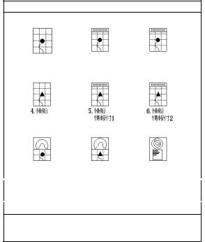
1.5Selecting a Display
Five screen displays are available: Plotter, Pilot, Navigation, Compass and Sounder. In addition to the full-screen display, you can divide the screen into half-screen combination displays.
1.Press the [DISP] key.
A DISPLAY MODE screen appears. There are four pages for the DISPLAY MODE screen.
DISPLAY MODE
|
|
|
2. PLOTTER |
3. PLOTTER |
|
|
1. PLOTTER |
|
|||||
NAV INFO 1 |
NAV INFO 2 |
|||||
|
|
|
||||
4. PILOT |
5. PILOT |
6. PILOT |
|
|
NAV INFO 1 |
NAV INFO |
2 |
7. COMPASS |
8. COMPASS |
9. GPS STATUS |
PLOTTER |
PILOT |
|
TURN KNOB TO SELECT DISPLAY MODE AND PRESS KNOB TO ENTER.
OR PRESS APPROPRIATE NUMERIC KEY TO SELECT DISPLAY MODE.
DISPLAY MODE screen
2.Press appropriate numeric key to choose a display.
Selected display replaces display made page
Note: The DISPLAY MODE screen can store a total of nine displays. You may program the DISPLAY MODE screen as desired. See paragraph 9.6.1.
1-10
1. BASIC OPERATION
1.6MOB Mark
The MOB (Man Overboard) mark functions to mark man overboard position. You can inscribe this mark from any mode, except while playing back, recording data or conducting a self-test.
|
|
|
MOB |
|
|
|
|
mark |
|
|
|
|
|
M |
|
|
|
|
(MOB) |
|
Range, bearing |
|
|
|
|
|
Current |
M |
162.5°M |
Man |
|
O |
0.49 nm |
|
|
position |
B |
||
overboard |
|
|
||
|
|
|
||
|
|
|
MOB data box |
|
|
|
|
Bearing and range |
|
|
|
|
to MOB position. |
|
MOB concept
1.Press and hold down the [SAVE/MOB] key immediately for about three seconds when someone falls onboard.
The display shows the waypoint number being saved (youngest empty waypoint number) the MOB position is being saved under followed by the MOB confirmation window.
WAYPOINT XXXXXX |
|
|
|
MAN OVER BOARD! |
|
IS SAVED. |
|
|
|
SET (MOB) AS |
|
CONTINUE PRESSING |
|
|
|
DESITINATION? |
|
After |
|||||
FOR MOB! |
YES … PRESS KNOB |
||||
several |
|||||
|
seconds. |
NO … PRESS CLEAR KEY |
|||
MOB mark messages
2.Push the [ENTER] knob to select the MOB position as the destination, or press the [CLEAR] key to only mark current ship's position as a waypoint. If you select the MOB position as the destination;
1)A full-screen PLOTTER NAV INFO 1 display replaces the display in use.
2)The MOB mark "M" appears at the MOB position and a dashed line runs between it and current position. This line shows the shortest course to the MOB position.
3)Range and bearing to the MOB position are shown in the MOB data box.
1-11
1. BASIC OPERATION
Note: The MOB mark can be deleted as follows.
c Press the [CURSOR ON/OFF] key to show the cursor.
d Operate the trackball to place the cursor on the MOB mark.
ePress the [CLEAR] key.
The following message will appear is on the screen:
WAYPOINT NAME XXXXXX
WILL BE DELETED.
ARE YOU SURE?
YES … PRESS KNOB
NO … PRESS CLEAR KEY
Confirmation message f Press the [ENTER] knob.
Then, the waypoint entered at step 1 on the previous page is erased. g Operate the trackball to place the cursor on the MOB mark.
hPress the [CLEAR] key.
A new message will appear on the screen:
WAYPOINT NAME (MOB) WILL BE DELETED.
ARE YOU SURE? YES … PRESS KNOB
NO … PRESS CLEAR KEY
When MOB is not set as destination
THIS WAYPOINT (MOB)
 IS USED FOR NAVIGATION. ILL IT BE DELETED?
YES … PRESS KNOB
NO … PRESS CLEAR KEY
When MOB is set as destination
Confirmation message
iPress the [ENTER] knob to erase the MOB mark.
1.7Using PROG Key
The [PROG 1] through [PROG 4] keys provide for instant display of a user-programmed options window (screen). Note that, the function for [VRM] key can also be. The default program of the [PROG] keys are as shown in the table below.
Key |
Functions |
PROG 1 |
Displays the WAYPOINT LIST. |
PROG 2 |
Displays DELETE SHIP’S TRACKS window. |
PROG 3 |
Each press changes the line style. |
PROG 4 |
Reset the trip distance to zero. |
•Note 1: To program plotter functions to the [PROG] keys or [VRM] keys, see paragraph 9.5.1.
1-12

1. BASIC OPERATION
1.8Simulation Mode
The simulation mode, which is for use by service technicians for demonstration purposes, provides simulated operation to help acquaint you with the many features your unit has to offer. All keys are operative.
“DEMO” appears at the bottom of the plotter (pilot) display (top of the sounder display) when any simulation mode is active.
Plotter
Own ship's mark moves from the default position at the speed set.
1.Press the [MENU] key to display main menu.
2.Press the [0] key to display SYSTEM SETUP menu.
0.SYSTEM SETUP
 1. DISPLAY SETUP
2.NAVIGATOR SETUP
3.PROGRAMMABLE KEYS & REMOTE CONTROLLER SETUP
4.DISPLAY MODES & NAV DATA WINDOW SETUP
5.I/O PORT SETUP
6.TEST & MEMORY CLEAR
7.SIMULATION MODE
8.
TURN KNOB. TO SELECT MENU AND PRESS KNOB TO ENTER.
OR PRESS APPROPRIATE NUMERIC KEY SELECT MENU.
System setup menu
1-13

1.BASIC OPERATION
3.Press the [7] key to display the SIMULATION MODE menu.
0-7. SIMULATION MODE SETUP
PLOTTER |
1. SIM |
|
2. LIVE |
SPEED |
09.9 kt |
|
|
COURSE |
1. DIRECTION |
2. 8 FIGURE |
|
DIRECTION |
000.0° |
|
|
LATITUDE |
45°35.000'N |
|
|
LONGITUDE |
125°00.000'W |
|
|
DATE & TIME |
03.01.01 00:00 |
|
|
TURN KNOB TO SELECT MENU.
SETUP SIMULATION MODE BY TRACKBALL.
Simulation mode setup menu
4.Rotate the [ENTER] knob to choose PLOTTER.
5.Roll the trackball in the left direction to choose "1. SIM." You may choose it by pressing the [1] key.
6.Rotate the [ENTER] knob to choose SPEED.
7.Enter speed (setting range: 0.0 to 99.9 kt) with the numeric keys, then press the [ENTER] knob.
8.Rotate the [ENTER] knob to choose COURSE.
9.Roll the trackball in the right-left direction to choose "1. DIRECTION" or "2. 8 FIGURE" as appropriate. You may choose the setting by pressing the numeric key.
DIRECTION: Track is traced according to course set. Go to step 10. 8 FIGURE: Track is traced in a figure-eight course. Go to step 12.
10.Rotate the [ENTER] knob to choose DIRECTION.
11.Enter course (setting range: 0.0 to 359.9) with the numeric keys, then press the [ENTER] knob.
12.Rotate the [ENTER] knob to choose LATITUDE.
13.Enter latitude with the numeric keys, and press the [ENTER] knob. Press the [CURSOR ON/OFF] key to switch from north to south and vice versa.
14.Rotate the [ENTER] knob to choose LONGITUDE.
15.Enter longitude with the numeric keys, and then press the [ENTER] knob. Press the [CURSOR ON/OFF] key to switch from east to west and vice versa.
16.Rotate the [ENTER] knob to choose DATE & TIME.
1-14

1. BASIC OPERATION
17.Enter start date and time with the numeric keys, in 24-hour notation and then press the [ENTER] knob.
Use 24-hour notation to enter time.
18.Press the [MENU] key several times to close the menu.
Note: To terminate the simulation mode, select "2. LIVE" at step 5.
1.9Menu Overview
Secondary operations are carried out through the menu. This section provides basic menu operating information.
1. Press the [MENU] key to display the main menu.
Red cursor
MENU
 1. WAYPOINT LIST
2.ROUTES LIST
3.MEMORY CARD OPERATIONS & DATA TRANSFER
4.MARKS/SHIP'S TRACKS SETUP
5.MARKS/SHIP'S TRACKS EDITION
6.ALARM SETUP
7.CHART SETUP
8.PLOTTER SETUP
9.
0. SYSTEM SETUP
TURN KNOB TO SELECT MENU AND PRESS KNOB TO ENTER.
OR PRESS APPROPRIATE NUMERIC KEY TO SELECT MENU.
Main menu
1-15
1.BASIC OPERATION
2.Select a menu item.
There are three ways to select a menu item. This manual uses method a).
a)Press the appropriate numeric key.
b)Rotate the [ENTER] knob to select the menu item desired, and then press the [ENTER] knob.
The red cursor appears at left side of the item selected. Rotate the [ENTER] knob clockwise to move the red cursor upward; counterclockwise for downward.
c)Roll the trackball in up-down direction to select item, and then press the [ENTER] knob.
For example, press the [8] key to display the PLOTTER SETUP menu.
Cursor (red rectangle)
|
|
|
|
|
|
|
|
|
|
|
|
8. PLOTTER SETUP |
|
|
|
|
|
|
|
|
|
|
|
|
|
|
|
|
|
|
|
|
|
|
|
LORAN-A GRI |
00-01 |
|
|
|
|
|
|
|
|
|
|
CORRECTION 1 |
+000.0 s |
|
|
|
|
|
|
|
|
||
CORRECTION 2 |
+000.0 s |
|
|
|
|
|
|
|
|
||
LORAN-C GRI |
00:11-29 |
|
|
|
|
|
|
|
|
|
|
CORRECTION 1 |
+000.0 s |
|
|
|
|
|
|
|
|
||
CORRECTION 2 |
+000.0 s |
|
|
|
|
|
|
|
|
||
DECCA CHAIN |
01 R-G |
|
|
|
|
|
|
|
|
|
|
CORRECTION 1 |
+00.00 LANE |
|
|
|
|
|
|
|
|
||
CORRECTION 2 |
+00.00 LANE |
|
|
|
|
|
|
|
|
||
|
|
|
|
|
|
|
|
||||
TD DISPLAY |
1. LORAN-A |
|
2. LORAN-C |
|
3. DECCA |
||||||
RESET TRIP LOG |
1. YES |
|
|
2. NO |
|
|
|
|
|
||
PLOTTER RANGE SETUP |
1. YES |
|
|
2. NO |
|
|
|
|
|
||
PANEL-DIMMER |
1 2 3 |
4 5 |
6 |
7 8 |
|
|
|
|
|
||
HUE |
1. DAY |
2. NIGHT |
3. TWILI |
|
4. MANUAL |
|
|||||
00:1L0 01:1L1 02:1L4 03:1L5 04:1L6 05:1L7 06:1S1 07:1S2 08:1S3 09:1S4 10:1S6 11:2H3 12:2H4 13:2H5 14:2H6 15:2S0 16:2S1 17:2S2 18:2S3 19:2S4 20:2S5 21:2S6 22:2S7
TURN KNOB TO SELECT MENU.
SELECT THE ITEM OF EACH MENU BY TRACKBALL.
Plotter setup menu
3.Rotate the [ENTER] knob to select item which you want to change the setting. You can also select item by rolling the trackball in up-down direction.
4.Roll the trackball in left-right direction to select option (with the red rectangle).
When the option is a numeral, you can select it by pressing the appropriate numeric key.
5.Press the [MENU] key several times to close the menu.
1-16

1. BASIC OPERATION
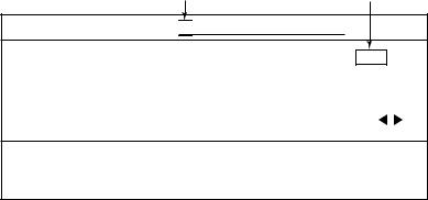
Entering numeric data
|
Cursor |
|||
|
|
|
|
|
8. PLOTTER SETUP |
|
|
|
|
|
|
|
|
|
LORAN-A GRI |
|
|
|
0-01 |
|
|
|
||
0 |
||||
CORRECTION 1 |
|
|
|
+000.0 s |
CORRECTION 2 |
|
+000.0 s |
||
TURN KNOB TO SELECT MENU.
SELECT THE ITEM OF EACH MENU BY TRACKBALL.
Plotter setup menu
1.Press the appropriate numeric key.
2.Press the [ENTER] knob.
You may also enter a value rotating the by [ENTER] knob.
Note: If you make a value mistake, move the cursor to the error position and then re-enter the proper value. The cursor for entering value is moved by rolling the trackball in left-right direction.
Press the [CLEAR] key to erase the all value on the line selected with the red cursor.
1-17
1. BASIC OPERATION
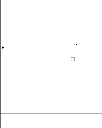
Entering character
Digit cursor Cursor
PASSWORD ENT AGAIN 

END
A B C D E F G H I J K L M N O P Q R S T U V W X Y
Z , - ! ? / & ^ = # |
1 2 3 4 5 6 7 8 9 0 _ _ _ _ _ |
|
a b c d e |
f g h i j |
k l m n o p q r s t u v w x y |
z _ _ _ _ |
_ _ _ _ _ _ _ _ _ _ _ _ _ _ _ _ _ _ _ |
|
SELECT ALPHANUMERIC CHARACTER BY TRACKBALL AND PRESS KNOB
TO ENTER. OR PRESS NUMERIC KEY TO NAME WAYPOINT.
MOVE THE CURSOR TO "END" ONCE THE EDITION IS FINISHED.
Ex. Set password, entering characters
1.Roll the trackball in up-down direction to select the first alphanumeric character with the cursor (red square).
Numeric may also be entered by pressing numeric key.
2.Press the [ENTER] knob.
Note: If you make a characteristic mistake, move the cursor to the error position and then re-enter the proper character. To move the digit cursor, select ◄ and then press the [ENTER] knob for left direction, or select ► and then press the [ENTER] knob for right direction.
Press the [CLEAR] key to erase the all characters.
3.Repeat steps 1 and 2 to complete the naming.
4.Finally, select "END" and then press the [ENTER] knob.
1-18
2.PLOTTER AND PILOT DISPLAY DESCRIPTION
2.1Plotter and Pilot Displays
The plotter and pilot displays can be shown with full-screen or in a half screen combined with the nav information window, compass or echo sounder display.
Press the [DISP] key, and then press the appropriate numeric key to show the display desired.
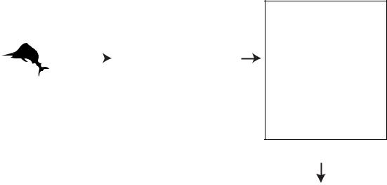
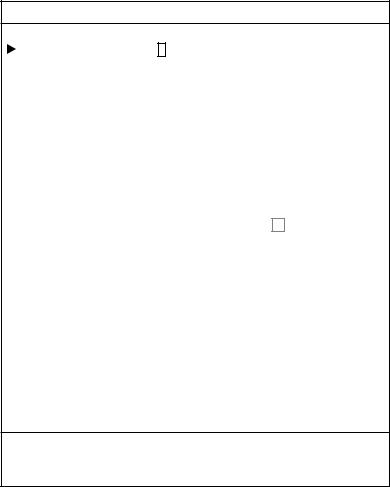
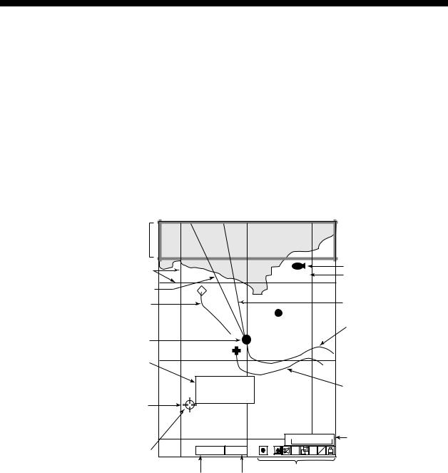
2.1.1Plotter display
The plotter display shows chart data, tracks, waypoints and marks on the display. The plotter display orientation is always north-up. North (zero degree) is at the top of the display and own ship (filled circle) is at the center of the screen.
When selecting PLOTTER
NAV INFO 1 (or 2),
NAV INFO window appears here.
Grid |
FISH |
Waypoint mark |
|
Waypoint name |
|||
43 |
Heading marker (white)
Other ship's track |
20 |
21 |
|
22 |
Course bar (light-blue) |
|
|
Own ship's track (main) |
|||
|
|
|
000001 |
|
|
Own ship's mark |
|
|
|
|
|
Mark information |
|
|
42 |
|
|
(appears when |
|
|
|
|
|
the cursor is on |
37˚04.640'N |
|
|
|
|
a mark) |
135˚21.047'E |
|
|
Own ship's track (sub) |
|
+ 4.5˚C 13.7m |
|
|
|||
Cursor |
|
|
|
||
|
|
|
|
|
|
|
|
|
41 |
0.3nm |
Scale |
|
|
|
|
||
|
GPS2D |
WGS84 |
H |
S A |
|
Mark |
V E L L |
|
|||
|
|
|
|
|
|
|
|
|
Icons |
|
|
|
GPS/DGPS |
Geodetic |
|
|
|
|
status |
datum |
|
|
|
PLOTTER display
2-1
2. PLOTTER AND PILOT DISPLAY DESCRIPTION
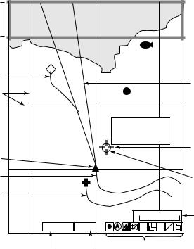
2.1.2Pilot display
The pilot display is similar to the plotter display, with the following differences.
1)The pilot display orientation is always auto course-up. The course is at the top of screen at the moment the pilot display is selected. A filled triangle marks own ship’s position. When own ship is off its intended course by 22.5° or more, it is automatically brought back to perpendicular.
2)The north mark ( ) appears at the bottom of the screen and points to north.
3)The grid lines denote the distance from own ship, not longitude/latitude.
Note: When north is not at the top of screen, the distance error may be larger than on the plotter display since the Mercator projection is used.
When selecting
PILOT NAV INFO 1 (or 2), the NAV INFO window appears here.
1
 Waypoint mark FISH
 Waypoint name
Other ship's track
Course bar (light-blue)
Grid
0.5 000001
37˚03.640'N
Heading marker (white)  135˚20.047'E
  Mark information
+ 4.5˚C 13.7m
|
|
|
|
Cursor |
Own ship's mark |
|
|
|
|
0.5 |
|
|
0.5 |
|
Own ship's track (main) |
|
|
|
Mark |
Own ship's track (sub) |
|
|
|
|
|
|
|
0.2nm Scale |
|
GPS2D |
WGS84 0.5 |
H |
S A |
L L |
V E |
||||
GPS/DGPS status |
|
Icons |
|
|
Geodetic datum |
|
|
||
Pilot display
2-2
Loading...