


 Loading...
Back
COLOR DGPS/PLOTTER
COLOR GPS/PLOTTER
GP-1650WD, GP-1650W FURUNO/NAVIONICS
GP-1650WD, GP-1650W FURUNO/C-MAP NT
9-52 Ashihara-cho,
Nishinomiya 662-8580, JAPAN
Telephone : |
0798-65-2111 |
|
Fax |
: |
0798-65-4200 |
All rights reserved. |
Printed in Japan |
Pub. No. OME-44240
( TATA ) GP-1650W/1650WD
The paper used in this manual is elemental chlorine free.
Your Local Agent/Dealer
FIRST EDITION : AUG. 2002
B1 : APR. 12, 2005
*00080935700*
*00080935700*
* 0 0 0 8 0 9 3 5 7 0 0 *
*OME44240B10*
*OME44240B10*
* O M E 4 4 2 4 0 B 1 0 *

 SAFETY INSTRUCTIONS
 WARNING
Do not open the equipment.
Hazardous voltage which can cause electrical shock, burn or serious injury exists inside the equipment. Only qualified
personnel should work inside the equipment.
Do not disassemble or modify the equipment.
Fire, electrical shock or serious injury can result.
Immediately turn off the power at the switchboard if the equipment is emitting smoke or fire.
Continued use of the equipment can cause fire or electrical shock. Contact a FURUNO agent for service.
Do not operate the equipment with wet hands.
Electrical shock can result.
Use the proper fuse.
Fuse rating is shown on the power cable. Use of a wrong fuse can result in damage to the equipment.
 About the TFT LCD
The TFT LCD is constructed using the latest LCD techniques, and displays 99.99% of its pixels. The remaining 0.01% of the pixels may drop out or blink, however this is not an indication of malfunction.
 CAUTION
Do not use the equipment for other than its intended purpose.
No one navigation device should ever be solely replied upon for the navigation of a vessel.
Always confirm position against all available aids to navigation, for safety of vessel and crew.
Use the proper gain setting.
Incorrect gain may produce wrong depth indication, possibly result ing in a dangerous situation. See "Adjusting the gain" on page 2-6.
The picture is not refreshed when picture advancement is stopped.
Maneuvering the vessel in this condition may result in a dangerous situation.
A warning label is attached to the equipment. Do not remove the label. If the label is missing or illegible, contact
a FURUNO agent or dealer.
WARNING |
Name: Warning Label (1) |
|
Type: 86-003-1011-1 |
||
To avoid electrical shock, do not |
||
remove cover. No user-serviceable |
Code No.: 100-236-231 |
|
parts inside. |
|
i

TABLE OF CONTENTS
FOREWORD .................................. |
iv |
SYSTEM CONFIGURATION ......... |
v |
WHAT IS WAAS?........................... |
vi |
1.OPERATIONAL OVERVIEW
1.1 |
Display Unit Controls ..................... |
1-1 |
1.2 |
Inserting Mini Chart Card ............... |
1-2 |
1.3 |
Turning the Power On/Off .............. |
1-2 |
1.4 |
Adjusting Tone and Brilliance ......... |
1-3 |
1.5 |
Plotter Displays.............................. |
1-4 |
1.6 |
Steering/Highway Displays ............ |
1-4 |
1.7 |
Menu Operation, Soft Keys ............ |
1-5 |
1.8 |
Demonstration Display................... |
1-6 |
2.PLOTTER DISPLAYS
2.1 |
Presentation Modes ....................... |
2-1 |
2.2 |
Cursor............................................ |
2-2 |
2.3 |
Shifting the Display ........................ |
2-2 |
2.4Displaying Nav Information Window2-2
2.5 |
Selecting Chart Scale/Range |
.........2-3 |
2.6 |
Mini Chart Cards............................ |
2-3 |
2.7 |
Navigation Data Display................. |
2-6 |
2.8 |
Steering Display............................. |
2-7 |
2.9 |
Highway Display ............................ |
2-8 |
2.10 |
Changing Operation Mode ............. |
2-9 |
2.11 |
Navigation Trip Distance .............. |
2-10 |
3. |
TRACK |
|
3.1 |
Displaying Track ............................ |
3-1 |
3.2Stopping/Restarting Plotting
|
of Track.......................................... |
3-1 |
3.3 |
Changing Track Color .................... |
3-2 |
3.4 |
Track Plotting Method, Interval....... |
3-2 |
3.5Changing Track Memory
Capacity......................................... |
3-3 |
3.6 Erasing Tracks............................... |
3-4 |
4.MARK
4.1 |
Entering Marks............................... |
4-1 |
4.2 |
Changing Mark Attributes............... |
4-2 |
4.3 |
Changing Mark Size....................... |
4-3 |
4.4 |
Erasing Marks................................ |
4-3 |
4.5Displaying Track and Mark
Points ............................................ |
4-4 |
4.6 Target Mark ................................... |
4-4 |
5.WAYPOINTS
5.1 |
Entering Waypoints ....................... |
5-1 |
5.2 |
Erasing Individual Waypoints......... |
5-4 |
5.3 |
Changing Waypoint Data............... |
5-5 |
5.4Changing Waypoint Position on
|
the Plotter Display ......................... |
5-5 |
5.5 |
Waypoint Mark Size....................... |
5-6 |
5.6 |
Searching Waypoints..................... |
5-6 |
6.ROUTES
6.1 |
Entering Routes............................. |
6-1 |
6.2 |
Connecting Routes........................ |
6-2 |
6.3 |
Inserting, Removing Waypoints ..... |
6-3 |
6.4 |
Creating Track-based Routes........ |
6-5 |
6.5 |
Erasing Routes.............................. |
6-6 |
7.NAVIGATION
7.1 |
Navigating to “Quick Points” |
.......... 7-1 |
7.2 |
Navigating to Waypoints |
|
|
(waypoint list) ................................ |
7-2 |
7.3Navigating to Ports, Port
|
Services ........................................ |
7-2 |
7.4 |
Following a Route.......................... |
7-4 |
7.5 |
Canceling Navigation .................... |
7-6 |
8.PLOTTER ALARMS
8.1 |
Introduction ................................... |
8-1 |
8.2 |
Audio Alarm On/Off ....................... |
8-1 |
8.3 |
Arrival Alarm.................................. |
8-2 |
8.4 |
Anchor Watch Alarm...................... |
8-2 |
8.5 |
XTE (Cross Track Error) Alarm...... |
8-3 |
8.6 |
Speed Alarm ................................. |
8-3 |
8.7 |
Proximity Alarm ............................. |
8-3 |
8.8 |
Alarm Information .......................... |
8-4 |
9.MEMORY CARD OPERATIONS
9.1 |
Formatting Memory Cards............. |
9-1 |
9.2 |
Saving Data to Memory Card ........ |
9-2 |
9.3 |
Loading Data from Memory Card .. |
9-3 |
ii
TABLE OF CONTENTS
10. |
CUSTOMIZING YOUR UNIT |
|
10.1 |
CHART SETUP OPTIONS menu 10-1 |
|
10.2 |
DISPLAY OPTIONS menu .......... |
10-3 |
10.3 |
GPS/DGPS/TD OPTIONS |
|
|
menu........................................... |
10-4 |
10.4 |
CONFIGURATION menu............. |
10-8 |
11. |
USING C-MAP NT MODEL |
|
11.1 |
Inserting Chart Card .................. |
11-1 |
11.2 |
Cursor and Data Display ............ |
11-2 |
11.3 |
Tidal Information.......................... |
11-3 |
11.4 |
Navigating to Ports, Port |
|
|
Services ...................................... |
11-4 |
11.5 |
Setting Chart Setup Options........ |
11-6 |
11.6 |
Selecting Chart Scale/Range ...... |
11-7 |
11.7 |
Displaying Program Number ....... |
11-8 |
12. |
MAINTENANCE & |
|
|
TROUBLESHOOTING |
|
12.1 |
Maintenance................................ |
12-1 |
12.2 |
Replacement of Fuse, Battery ..... |
12-2 |
12.3 |
Simple Troubleshooting............... |
12-2 |
12.4 |
Error Messages........................... |
12-3 |
12.5 |
Diagnostic Tests .......................... |
12-3 |
12.6 |
Clearing Memories ...................... |
12-5 |
APPENDIX |
|
|
MENU TREE .......................................... |
A-1 |
|
LORAN C CHAINS................................. |
A-3 |
|
DECCA CHAINS .................................... |
A-4 |
|
WORLD TIME ........................................ |
A-5 |
|
GEODETIC CHART LIST....................... |
A-6 |
|
SPECIFICATIONS..................... |
SP-1 |
|
INDEX
DECLARATION OF CONFORMITY
iii

FOREWORD
A Word to GP-1650WD/1650W Owners
Congratulations on your choice of the FURUNO GP-1650WD COLOR DGPS/PLOTTER, GP-1650W COLOR GPS/PLOTTER. We are confident you will see why the FURUNO name has become synonymous with quality and reliability.
For over 50 years FURUNO Electric Company has enjoyed an enviable reputation for innovative and dependable marine electronics equipment. This dedication to excellence is furthered by our extensive global network of agents and dealers.
This equipment is designed and constructed to meet the rigorous demands of the marine environment. However, no machine can perform its intended function unless installed, operated and maintained properly. Please carefully read and follow the recommended procedures for operation and maintenance.
We would appreciate hearing from you, the end-user, about whether we are achieving our purposes.
Thank you for considering and purchasing FURUNO equipment.
Features
The GP-1650WD provides a totally integrated DGPS beacon receiver, WAAS function, GPS receiver and color video plotter. The GP-1650W mostly shares the same features with the GP-1650WD except it does not have a DGPS beacon receiver.
Navigation information is displayed on a bright 5.6-inch color TFT LCD. On-screen information shown are position, range and bearing to cursor position, range, bearing, ETA and TTG to waypoint, etc.
A high sensitivity receiver tracks up to twelve (WAAS: thirteen) satellites simultaneously. An 8-state Kalman filter ensures optimum accuracy in determination of vessel position, course and speed.
C-MAP NT-FP chart card is available for the GP-1650WD/1650W.
The main features of the
GP-1650WD/1650W are
•WAAS capability.
•Comprehensive navigation data displays.
•Bright 5.6-inch color TFT LCD with temperature compensated tone and brilliance control.
•Automatic coastline chart loading.
•Position display in latitude and longitude, Loran C or Decca TDs.
•Improved position accuracy with optional DGPS beacon receiver (GP-1650W).
•Accepts both FURUNO and NAVIONICS chart card or FURUNO and C-MAP NT mini chart cards.
•Alarms: Arrival, Anchor Watch, Cross-track Error, Speed and Proximity.
•Man overboard feature records latitude and longitude coordinates at time of man overboard.
•“Highway” display provides graphic presentation of ship’s track and is useful for monitoring cross track error.
iv
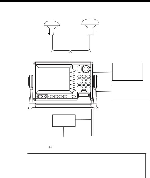
SYSTEM CONFIGURATION
GPA-019 (GP-1650WD)
GPA-017 (GP-1650W)
ANTENNA UNIT
Receives signal from GPS satellite and beacon reference station. (GP-1650WD only)
DISPLAY UNIT
External equipment (Autopilot, etc.)
DGPS beacon receiver (GP-1650W only)
Rectifier
PR-62
Ship's mains 100/110/115/220/230 VAC
Ship's mains
1 , 50/60 Hz
12-24 VDC
This GPS receiver complies with Canadian standard RSS-210 (Low Power License-Exempt Radio communication Devices).
Operation is subject to the following two conditions:
(1)this device may not cause interference, and
(2)this device must accept any interference, including interference that may cause undesired operation of the device.
v

WHAT IS WAAS?
WAAS, available in North America, is a provider in the worldwide SBAS (Satellite Based Augmentation System) navigation system. An SBAS provider furnishes GPS signal corrections to SBAS users. Two more SBAS providers are also currently under development, MSAS (Multi-Functional Satellite Augmentation System) for Japan and EGNOS (Euro Geostationary Navigation Overlay Service) for Europe. All providers will be compatible with one another, thus providing “seamless” position fixes to SBAS users.
150° W |
120° W |
90° W |
60° W |
30° W |
0 |
30° E |
60° E |
90° E |
120° E |
150° E |
|
60° N |
|
|
|
|
|
|
|
|
|
|
60° N |
40° N |
|
|
|
|
|
|
EGNOS |
|
MSAS |
40° N |
|
|
|
|
|
|
|
|
|
|
|
|
|
20° N |
|
|
|
|
|
|
|
|
|
|
20° N |
0 |
|
|
|
122 |
120 |
|
131 |
|
|
134 |
0 |
|
WAAS |
|
|
|
|
|
|
|
|
|
|
20° S |
|
|
|
|
|
|
|
|
|
|
20° S |
40° S |
|
|
|
|
|
|
|
|
|
|
40° S |
60° S |
|
|
|
|
|
|
|
|
|
|
60° S |
150° W |
120° W |
90° W |
60° W |
30° W |
0 |
30° E |
60° E |
90° E |
120° E |
150° E |
|
Satellite, Region |
Position |
120, AOR-E |
15.5° W |
122, AOR-W |
54° W |
131, IOR |
64.5° E |
134, POR |
178° E |
Initial operation time
WAAS: 2003
EGNOS: 2004
MSAS: 2005
At the time of this software release, SBAS is still under development. (Providers are expected to have initial operations capability from the times shown above.) During this developmental period, which may last for several years, there is no guarantee of the accuracy, integrity, continuity, or availability of the SBAS signal. Furuno will accept no responsibility for the use of the signal for other than the above stated purpose. It is the user’s responsibility to exercise common prudence and navigational judgment while using the SBAS signal in the developmental phase.
Note: This manual uses “WAAS” when referring to any SBAS provider.
vi

1. OPERATIONAL OVERVIEW
This chapter acquaints you with the basics of your unit - from turning on the power to the soft key menu operation.
1.1Display Unit Controls
•Registers own ship's positions.
•Marks man overboard position, event position.
Registers items on menus.
Soft key's functions change
|
|
Cursor pad |
||
|
|
• |
Shifts cursor and display. |
|
|
|
• |
Selects items on menus. |
|
SAVE |
|
|
|
|
MOB |
|
|
|
|
ENTER |
|
|
|
|
ABC |
DEF |
GHI |
|
|
1 |
2 |
3 |
Enter alphanumeric data. |
|
JKL |
MNO |
PQR |
||
|
||||
4 |
5 |
6 |
|
|
depending on the display.
POWER |
ALARM |
PLOT |
XTE |
WPT |
|
BRILL |
HIWAY |
RTE |
|||
|
|
STU |
VWX |
YZ& |
|
7 |
8 |
9 |
|
CLEAR |
_'# |
MENU |
Opens/closes |
0 |
|||
|
|
|
the main menu. |
HIDE |
|
|
Mini chart card slot. |
SHOW |
|
|
|
•Clears data.
•Erases selected waypoint.
•Silences audible alarm.
Displays/hides the soft key menu, nav data, mode indication.
Displays the waypoint & route menu.
Alternately selects Steering display and Highway display.
Selects plot display.
Displays the alarm menu.
•Long press: Turns power off.
•Touch and release: Turns power on.
Opens the window for adjustment of tone and brilliance.
Display unit
1-1
1. OPERATIONAL OVERVIEW
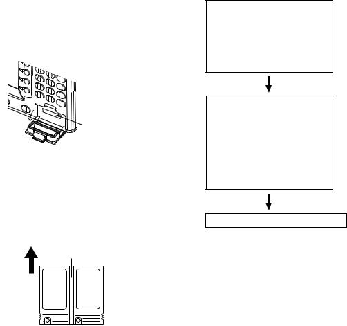
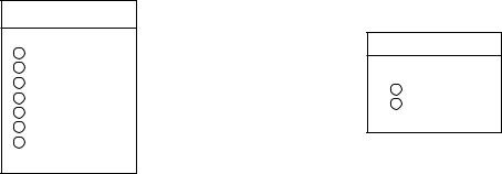
1.2Inserting Mini Chart Card
Insert appropriate mini chart card before turning on the power.
Note: Static electricity can be passed through your fingers to a memory card and destroy the contents of the card. To prevent this, always touch a metallic object, such as a steel desk, before handling a memory card.
1.Push down the lid catch to open the mini chart card slot cover.
Card slot
Location of mini chart card slot cover
2.Insert appropriate mini chart card groove side up.
Inserting groove side up.
Mini chart card
Direction of mini chart card
3.Close the slot cover to protect the chart drive. (Keep the slot cover closed at all times.)
Note: Turn off power before inserting or ejecting the mini chart card.
1.3Turning the Power On/Off
Turning the power on
Press the [POWER/BRILL] key at bottom left-hand side of the display unit to turn on the power. When the unit is turned on, it proceeds in the sequence shown in the figure in below, after displaying the FURUNO information display.
Displayed for about five seconds.
START UP TEST
PROGRAM |
OK |
|
|
RAM |
OK |
|
|
BACKUP DATA |
OK |
|
|
INTERNAL BATTERY |
OK |
|
|
GPS |
OK |
- - WARNING - -
NO NATIONAL HYDROGRAPHIC OFFICE
HAS VERIFIED THE INFORMATION
IN THIS COASTLINE DATA CARD AND
NONE ACCEPT LIABILITY FOR THE
ACCURACY OF REPRODUCTION OR ANY
MODIFICATIONS MADE THEREAFTER.
THIS PRODUCT WITH THIS COASTLINE
DATA CARD DOES NOT REPLACE THE
REQUIREMENT TO USE THE
APPROPRIATE PRODUCTS FOR
NAVIGATION ACCORDING TO NATIONAL
AND INTERNATIONAL REGULATONS.
FURUNO ELECTRIC CO., LTD.
Displayed for about 30 seconds, or press any key to escape.
The last-used display appears.
Start-up sequence
For any NG on the start up test display, request service.
The GP-1650WD/1650W takes about 90 seconds to find its position when turned on for the very first time. This is because the equipment has no satellite data, called the Almanac, in its database. If you want to lessen the time needed to find position you may enter your position manually (default position: San Francisco, USA) on the GPS SETUP OPTIONS menu.
Thereafter it takes about 12 seconds to find position each time the power is turned on.
1-2
When the satellite signal is being received normally, the GP-1650WD/1650W displays various abbreviations at the bottom left-hand corner of the display which show DGPS/GPS receiver status. The table in below shows these abbreviations and their meanings.
Display abbreviations
Indication |
Meaning |
|
|
|
|
GPS 2D |
2D (dimension) GPS |
|
position fix |
||
|
||
|
|
|
GPS 3D |
3D GPS position fix |
|
|
|
|
DGPS 2D |
2D differential GPS |
|
(GP-1650WD) |
position fix |
|
|
|
|
DGPS 3D |
3D differential GPS |
|
(GP-1650WD) |
position fix |
|
|
|
|
NO FIX |
Position cannot be |
|
found. |
||
|
||
|
|
|
DOP |
DOP error |
|
|
|
|
DEMO |
Simulation mode |
|
|
|
|
GPS W2D |
2D WAAS position fix |
|
|
|
|
GPS W3D |
3D WAAS position fix |
|
|
|
Turning the power off
Press and hold down the [POWER/BRILL] key until the screen goes blank. The time remaining until the power is turned off is shown on the screen.
Note: The example screens shown in this manual may not match the screen you see on your display. The screen you see depends on your system configuration and equipment settings.
1.OPERATIONAL OVERVIEW
1.4Adjusting Tone and Brilliance
1.Press the [POWER/BRILL] key with a touch-and-release action. The tone and brilliance setting window appears.
Functions
TONE
TONE
TONE
BRILL
BRILL
BRILL
RETURN
Tone and display brilliance setting window
Soft keys
Tone and brilliance adjustment window
2.Press ◄ or ► on the cursor pad to adjust display tone.
3.Press ▲ or ▼ on the cursor pad to adjust display brilliance.
Note that tone and brilliance can also be adjusted by soft keys. After pressing the [POWER/BRILL] key, use the appropriate soft key to adjust tone or brilliance.
Note: Tone or brilliance must be adjusted within 10 seconds after pressing the [POWER/BRILL] key or the tone and brilliance adjustment window will be erased.
1-3
1. OPERATIONAL OVERVIEW
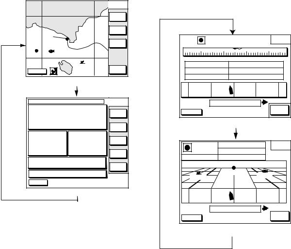
1.5Plotter Displays
Press the [PLOT] key. Each time this key is pressed, the display mode changes in the sequence shown below. For display mode, refer to Chapter 2.
NORTH
UP
ZOOM
IN
ZOOM
OUT
COURSE
UP
WP-002 FISH
|
|
|
BRIDGE |
|
NAV |
|
DGPS 3D |
|
|
|
|
|
|
|
|
|
|
|
POS |
|
|
[Plotter Display] |
|
|
|||
DATE: JUN 02 2002 |
TIME 23:59:59 |
LAT/LON |
||||
POSITION |
|
|
TRIP:123nm |
|
|
|
34° |
56.789' N |
LAT |
||||
LON |
||||||
135° |
56.789' E TD |
|||||
SPD |
|
|
RNG |
|
|
|
16.3 |
kt |
27.2 nm |
|
ZOOM |
||
CSE |
|
° |
BRG |
° |
SAT |
|
245.8 |
245.0 |
|
INFO |
|||
|
|
|
|
|
|
|
DATUM: WGS-84 |
|
|
BEACON |
|||
|
|
|
|
|
||
|
|
|
|
|
|
INFO |
TMP |
65.8° F |
DEP |
20ft |
|
|
|
DGPS 3D |
|
|
|
|
|
|
|
[Nav Data Display] |
|
|
|||
Display modes (plotter key)
1.6Steering/Highway Displays
Press the [XTE/HIWAY] key. Each time this key is pressed, the display mode changes in the sequence shown below. For display mode, refer to Chapter 2.
|
Q P < 0 1 > |
CROSS |
||
|
TRACK |
|||
230 |
240 |
|
250 |
260 |
BRG 2 4 5 . 0 ° |
RNG |
2 7 . 2 n m |
||
CSE 2 3 4 . 5 ° |
SPD |
1 3 . 6 k t |
||
TTG |
1h 59m |
ETA |
29th 14:50 |
|
0.1nm |
XTE |
000.02nm |
0.1nm |
|
|
EDIT |
|||
DGPS 3D |
|
|
|
|
|
|
|
XT-LMT |
|
|
[Steering Display] |
|
||
|
001WPT |
BRG |
|
9 4 . 6 ° |
HIGHWAY |
|
|
RNG |
|
1 . 8 8 n m |
|
||
|
|
|
|
|
||
CSE |
87.8° |
|
SPD |
|
1 0 . 0 k t |
|
|
|
|
001WPT |
FISH01 |
||
YUUKI |
|
|
|
|||
|
|
|
|
|
||
0.1nm |
|
XTE |
000.02nm |
0.1nm |
||
|
|
EDIT |
||||
DGPS 3D |
|
|
|
|
||
|
|
|
|
XT-LMT |
||
|
[Highway Display] |
|
||||
Display modes (XTE/HIWAY key)
1-4
1.7Menu Operation, Soft Keys
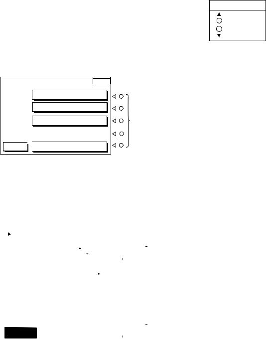
Most operations are carried out through the menu which is opened and closed with the [MENU] key. Menus may be selected with the five soft keys to the right of menus. Options are selected with the cursor pad.
1.Press the [MENU] key to display the main menu.
MENU |
|
|
CHART SETUP OPTIONS |
|
|
DISPLAY OPTIONS |
|
|
GPS/DGPS/TD OPTIONS |
Soft |
|
keys |
||
|
DGPS 3D 
 CONFIGURATION
Main menu
2.Press appropriate soft key to display desired menu. For example, press the DISPLAY OPTIONS soft key. The name of the menu in use appears at the top right corner of the display.
|
|
|
|
|
|
DISPLAY |
|
|
|
RNG & BRG MODE |
RHUMB LINE |
|
|||
|
|
|
SETUP |
||||
|
|
RANGE/SPEED UNIT |
nm/kt |
|
|
|
|
|
|
DEPTH UNIT |
ft |
|
|
|
|
|
|
TEMP UNIT |
F |
|
EDIT |
|
|
|
|
LAT/LON DISPLAY |
DD MM.MMM' |
|
|
||
|
|
|
|
|
|||
|
|
TIME DISPLAY |
24 HOUR |
|
|
|
|
|
|
WAYPOINTS SW |
AUTO2 |
|
|
|
|
|
|
COURSE VECTOR |
LINE |
|
|
|
|
|
|
BEARING |
MAGNETIC |
|
|
|
|
|
|
MAG VARIATION |
AUTO 01.3 E |
|
|
|
|
|
|
TD DISPLAY |
LORAN C |
|
|
|
|
|
|
POSITION DISPLAY |
LAT/LON |
|
|
|
|
|
|
SET GO TO METHOD |
1 POINT |
|
|
|
|
|
|
OPERATION MODE |
PLEASURE |
|
|
|
|
|
|
LANGUAGE |
ENGLISH |
|
|
|
|
|
|
|
|
|
|
|
|
|
|
|
|
|
|
|
|
|
DGPS 3D |
|
|
|
RETURN |
|
|
|
|
|
|
|
|
||
|
|
|
|
|
|
|
|
Display setup menu
1.OPERATIONAL OVERVIEW
3.Select item with the cursor pad, and press the EDIT soft key. For example, select TIME DISPLAY.
TIME DISPLAY
12 HOUR  24 HOUR
Time display window
4.Use the cursor pad to change the setting.
5.Press the ENTER soft key or [ENTER] key.
6.Press the RETURN soft key.
7.Press the [PLOT] key to finish.
1-5
1. OPERATIONAL OVERVIEW
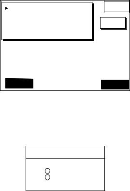
1.8Demonstration Display
The demonstration display provides simulated operation of this unit. On the plotter display, own ship tracks, at the speed selected, a figure eight course or any course you enter, starting from position entered. All controls are operative; you may set destination, enter waypoints, etc
1.Press the [MENU] key, followed by the CONFIGURATION and SYSTEM MENU soft keys to open the system menu.
2.Press the DEMONSTRATION MODE soft key to open the demonstration setting screen.
DEMO MODE |
OFF |
DEMO |
MODE |
||
DEMO SPEED |
10.0kt |
|
DEMO COURSE |
000.0° |
EDIT |
DEMO START LAT |
34° 12.34'N |
|
DEMO START LON |
135° 12.34'E |
|
DGPS 3D |
|
|
|
RETURN |
|
|
|
|
Demo setting screen
3.Press ▲ or ▼ to select DEMO MODE.
4.Press the EDIT soft key to show the demo mode window.
DEMO MODE
▲
 ON
ON
OFF
▼
Demo mode window
5.Press ▲ to select ON.
6.Press the ENTER soft key or the [ENTER] key.
7.Select DEMO SPEED and press the EDIT soft key. Enter speed. Select digit with ◄/► and enter appropriate numeric value with the numeric keys.
8.Press the ENTER soft key or [ENTER] key.
9.Select DEMO COURSE and press the
EDIT soft key. Select how you want the courseline to be traced; by FIGURE 8 or DIR.(ection). For DIR., enter course.
10.Press the ENTER soft key or [ENTER] key.
11.Select DEMO START LAT., and press the EDIT soft key. Enter latitude. Use the N< - > S soft key to switch coordinates if necessary.
12.Press the ENTER soft key or [ENTER] key.
13Select DEMO START LONG, and press the EDIT soft key. Enter longitude. Use the E< - > W soft key to switch coordinates if necessary.
14.Press the ENTER soft key or [ENTER] key.
15.Press the RETURN soft key.
16.Press the [PLOT] soft key.
To cancel the demonstration display, set DEMO MODE to OFF.
1-6
2. PLOTTER DISPLAYS
2.1Presentation Modes
The plotter display mainly shows chart, ship’s track, waypoints, and navigation data.
Three types of display presentations are provided for the normal plotter display: north-up, course-up and auto course-up. To change the mode, use the presentation mode selection soft key, which is the 3rd soft key from the top.
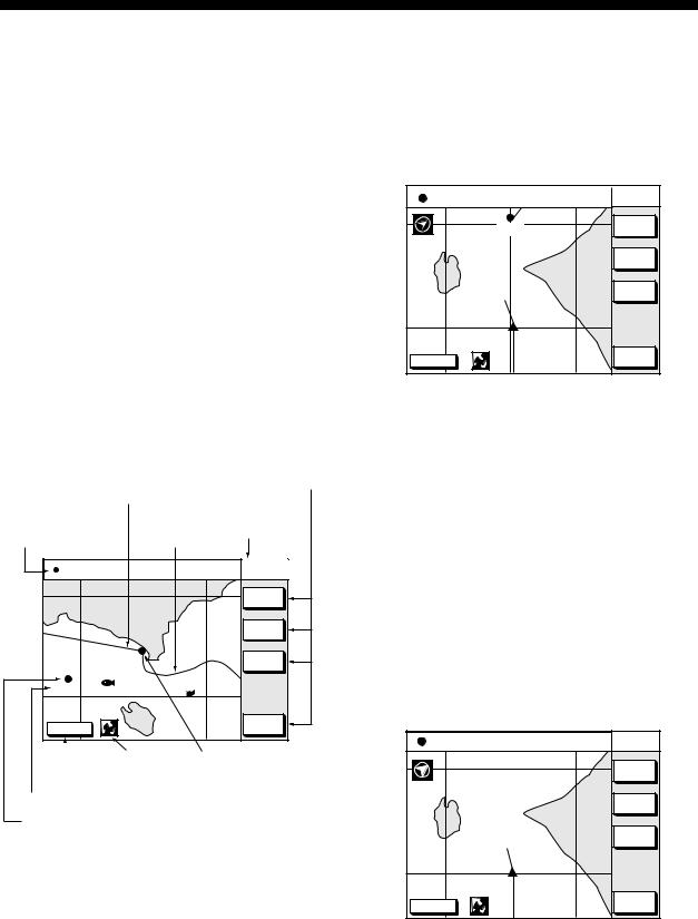
North-up
Press the NORTH UP soft key to show the north-up display. North (zero degree) is at the top of the display and own ship is at the center of the screen. Own ship marker is a filled circle. This mode is useful for long-range navigation.
|
Functions for |
Course bar |
soft key |
Current display mode Nav information Track (north-up) window
34° |
12.345' N |
CSE |
245.8° |
NORTH |
135° |
12.345' E |
SPD |
16.3kt |
UP |
|
|
|
|
ZOOM |
|
|
|
|
IN |
|
|
|
|
ZOOM |
|
|
|
|
OUT |
|
|
|
|
COURSE |
|
|
|
|
UP |
002WP |
FISH |
|
|
|
|
|
|
|
|
|
|
BRIDGE |
|
|
DGPS 3D |
|
|
|
NAV |
|
|
|
WPT |
|
|
|
Icon (chart) |
Own ship |
|
GPS status |
||||
|
marker |
|||
|
|
|
||
Waypoint name
Waypoint mark
Plotter display, north-up mode
Course-up
Press the COURSE UP soft key to show the course-up display. When destination is set it is at the top of the screen, and the north mark appears at the upper left side of the
screen and points to north. A filled triangle marks own ship’s position.
When destination is not set, the course is upward on the screen at the moment the course-up mode is selected.
34° |
12.345' N |
CSE |
245.8° |
COURSE |
135° 12.345' E |
SPD |
16.3kt |
UP |
|
|
QP<01> |
|
ZOOM |
|
|
|
IN |
||
|
|
|
|
ZOOM |
|
|
|
|
OUT |
|
|
|
|
AUTO |
|
|
|
|
C.U. |
DGPS 3D |
|
|
|
NAV |
|
|
|
WPT |
|
Plotter display, course-up mode
Auto course-up
Press the AUTO C.U. soft key to show the automatic course-up display. When destination is set it is at the top of the screen, and the north mark appears at the upper left side of the screen and points to north. A filled triangle marks own ship’s position. The course is at the top of screen at the moment the automatic course-up mode is selected. When own ship is off its intended course by 22.5° or more, it is automatically brought back to perpendicular.
34° 12.345' N |
CSE |
245.8° |
AUTO |
135° 12.345' E |
SPD |
16.3kt |
C-UP |
|
|
|
ZOOM |
|
|
|
IN |
|
|
|
ZOOM |
|
|
|
OUT |
|
|
|
NORTH |
|
|
|
UP |
DGPS 3D |
|
|
NAV |
|
|
WPT |
Auto course-up mode
2-1
2. PLOTTER DISPLAYS
2.2Cursor
Turning on the cursor, shifting the cursor
Press the cursor pad to turn the cursor on, and the cursor appears at the own ship’s position. Operate the cursor pad to shift the cursor. The cursor moves in the direction of the arrow or diagonal pressed on the cursor pad.
Cursor position is displayed in latitude and longitude or Loran or Decca TDs (depending on menu setting) at the top of the plotter display when the cursor is on.
34° |
12.345' N FROM |
16.45nm |
NORTH |
|
135° |
12.345' E |
OS |
276.9° |
UP |
|
|
|
|
ZOOM |
|
|
|
|
IN |
|
|
|
|
ZOOM |
|
|
|
|
OUT |
|
|
|
|
COURSE |
|
|
|
|
UP |
|
|
|
|
GO TO |
|
|
|
|
CURSOR |
DGPS 3D |
|
|
|
CENTER |
|
|
|
|
|
Data displayed on the plotter display when the cursor is on
Turning off the cursor, returning own ship marker to screen center
The CENTER soft key turns off the cursor and returns own ship marker to screen center.
When the cursor is off, own ship position is shown.
2.3Shifting the Display
The display can be shifted on the plotter display.
1.Press the cursor pad to display the cursor.
2.Locate the cursor at a screen edge. The screen shifts in the direction opposite of cursor location.
2.4Displaying Nav Information Window
The nav information window can show four data: own ship position, waypoint position, own ship’s speed/course and off.
Press the soft key at the bottom of screen. Each press key changes data in the sequence shown below. Soft key name also changes.
NAV POS soft key
Displays own ship's position, course and speed.
NAV WPT soft key
Displays range/bearing to the selected waypoint, chart scale and own ship's course.
NAV S/C soft key
Displays own ship's course/speed and water temperature*/depth.
NAV OFF soft key
Turns off the window.
*: Water temperature sensor is required.
Sequence of pressing the bottom soft key
When the cursor is on, the window at the top of the display shows the cursor position instead of own ship’s. To change the window mode when the cursor is on, press the CENTER soft key to show the appropriate soft key.
2-2
2.5Selecting Chart Scale/Range
Chart scale (range) may be selected with the ZOOM IN or ZOOM OUT soft key. ZOOM IN expands the chart; ZOOM OUT shrinks it.
2. PLOTTER DISPLAYS
2.6Mini Chart Cards
The mini chart cards contain nautical charts. When you insert a suitable mini chart card in the slot and your boat is near land, a chart appears.
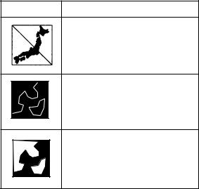
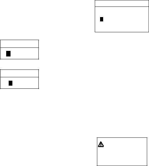
When a wrong card is inserted or a wrong chart scale is selected, the land will be hollow. Insert the proper card and select a suitable chart scale. Chart icons appear to help you select a suitable chart scale. The table below shows the chart icons and their meanings.
Chart icons and their meanings
Icon Meaning
Proper card is not inserted or chart scale is too small. Press the soft key ZOOM IN to adjust chart scale.
Chart scale is too large. Press the soft key ZOOM OUT to adjust chart scale.
Suitable chart scale is selected.
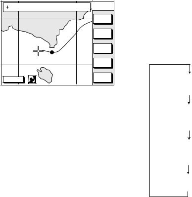
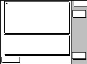
Indices and chart enlargement
When the ZOOM OUT soft key is used, you will see several frames appear on the chart. These frames are called indices and they show you what parts of the chart can be enlarged in the current picture range. The areas circumscribed with smaller frames can be enlarged, but the area enclosed by the largest frame cannot. These indices can be erased through the menu. See page 10-2.
2-3
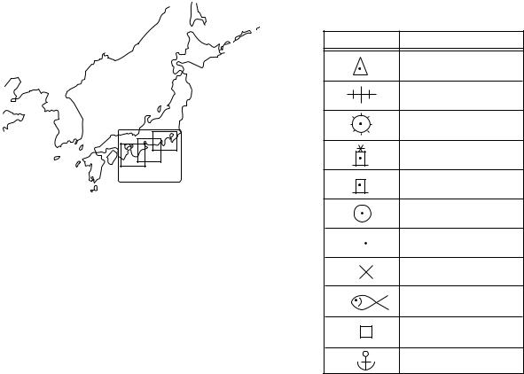
2. PLOTTER DISPLAYS
Sample chart (Japan and South Korea) showing indices
Remarks on chart display
A chart will not be displayed in the following conditions:
•When the chart scale is too large or too small.
When this happens, select proper chart scale.
•When scrolling the chart outside the indices.
Chart symbols
FURUNO mini chart card
The table below shows FURUNO mini chart symbols and their meanings.
FURUNO chart symbols
Symbol Description
Summit
Wreck
Lighthouse
Lighted Buoy
Buoy
Radio Station
Position of Sounding
Obstruction
Fishing Reef
Platform
Anchorage
Comparison of FURUNO and Nav-ChartsTM
chart cards
Item |
FURUNO |
Nav-Charts™ |
|
|
|
|
|
Dot scrolling |
YES |
YES |
|
capability |
|||
|
|
||
|
|
|
|
Course-up |
YES |
YES |
|
display |
|||
|
|
||
|
|
|
|
Lighthouse data |
YES *3 |
YES |
|
presentation |
|
|
|
|
|
|
|
Zoom at cursor |
YES |
*1 |
|
position |
|||
|
|
||
|
|
|
|
Range at |
0.125, 0.5, |
Same as left |
|
Equator |
1, 2... 2048 |
|
|
|
nm |
|
|
|
|
|
|
Chart offset |
YES |
YES |
|
data entry |
|||
|
|
||
|
|
|
|
Centering |
YES |
*2 |
|
|
|
|
*1 Nav-ChartsTM chart may not center the cursor perfectly.
*2 Nav-ChartsTM chart may not center own ship's position perfectly.
*3 Newly designed chart cards containing lighthouse data. Chart cards for North America area are completed, and others are in production.
*4 Nav-ChartsTM is the registered trademark of NAVIONICS INC.
2-4
Aid to navigation data
Selected FURUNO and NAVIONICS mini chart cards can show buoy and lighthouse data. Simply place the cursor on the lighthouse or buoy mark.
Place the cursor on
a lighthouse or buoy mark.
Placing the cursor on the mark
Example of data displayed
Range and bearing |
Period (ex.: 6 seconds) |
from own ship |
Visibility in nautical |
|
mile (ex.: 12 miles) |
NAVAID: /FL 6S 12M |
|
||
FROM OS |
52.38nm 48.0° |
|
|
|
FL |
: Flashing |
|
|
F |
: Fixed light |
|
|
F FL : Fixed and Flashing light |
||
|
MO |
: Morse code light |
|
|
Oc |
: Occulting light |
|
Example of buoy, lighthouse data
2. PLOTTER DISPLAYS
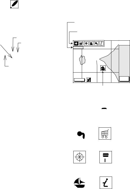
Port service icons (Nav-ChartsTM cards)
Selected Nav-ChartsTM mini chart cards show by icons services available at ports. Use the cursor pad to place the cursor on the sailboat icon (denotes a port or harbor), and then press the [ENTER] key. The services available appear at the top of the display.
Detailed information of service selected
List of services
at the port selected
|
NORTH |
|
UP |
FIRST AID |
|
DGPS 3D |
CANCEL |
|
Sailboat mark (Port)
Plotter display showing Nav-ChartsTM port service display
|
|
|
|
|
|
|
|
|
|
|
|
|
|
|
|
|
|
|
|
|
|
|
|
|
|
|
|
|
|
|
|
|
|
|
|
|
|
|
|
|
|
|
|
|
|
|
|
|
|
|
|
|
|
|
|
|
|
|
|
|
|
|
|
|
|
|
|
|
|
|
|
|
|
|
|
|
|
|
|
|
|
|
|
Emergency |
Fueling station |
||||||||||||
medical service |
|||||||||||||
|
|
|
|
|
|
||||||||
|
|
|
|
|
|
|
|
|
|
|
|
|
|
|
|
|
|
|
|
|
|
|
|
|
|
|
|
|
|
|
|
|
|
|
|
|
|
|
|
|
|
|
|
|
|
|
|
|
|
|
|
|
|
|
|
|
|
|
|
|
|
|
|
|
|
|
|
|
|
|
|
|
|
|
|
|
|
|
|
|
|
|
|
Water |
Traveler's |
supply station |
service station |
Customer |
|
|
|
|
|||
Marine |
|||||||
service station |
equipment service |
||||||
|
|
|
|
|
|
|
|
|
|
|
|
|
|
|
|
|
|
|
|
|
|
|
|
|
|
|
|
|
|
|
|
Port |
Information center |
Port service icons
2-5
2. PLOTTER DISPLAYS
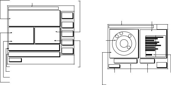
2.7Navigation Data Display
The navigation data display provide generic navigation data and DGPS/GPS information. Press the [PLOT] several times to show the navigation data display.
Position |
|
Date |
|
Range to waypoint |
|
DATE: JUN 30 2002 TIME 23:59:59 |
LAT/LON |
||||
POSITION |
|
|
|
TRIP:123nm |
LAT |
34° |
|
|
|
|
|
|
56.789' N LON |
||||
135° |
|
56.789' E TD |
|||
SPD |
|
RNG |
|
|
|
12.5 |
kt |
|
123.25 nm |
ZOOM |
|
CSE |
° |
BRG |
° |
SAT |
|
359.9 |
|
299.9 |
INFO |
||
DATUM: WGS-84 |
|
|
|||
|
|
|
|||
|
|
|
|
|
BEACON |
TMP 65.8° F DEP |
|
20.8ft |
INFO |
||
|
|
||||
DGPS 3D |
|
|
|
|
|
Temperature, depth Bearing to waypoint Geodetic chart datum
Course
Speed
Navigation data display
The navigation data display shows your position by L/L or TD (Loran-C, Decca). To change position format, press the appropriate LAT/LON or TD soft key.
Enlarging an indication
An indication on the screen may be enlarged as follows:
1.Use the cursor pad to select the indication which you wish to enlarge. Selected indication is circumscribed with a red cursor.
2.Press the ZOOM soft key.
To return to the normal nav data display, press the RETURN soft key.
GPS satellite monitor display
The GPS satellite monitor display shows information about GPS satellites.
Press the SAT INFO soft key. Your display should look something like the following illustration.
|
Receive signal level |
Date |
Bars show satellite |
signal level. |
|
DATE: JUN 30 2002 |
|
TIME 23:59:59 |
|
SAT |
||||
|
|
N |
|
|
|
|
|
|
INFO |
|
|
|
|
|
SAT |
|
SNR |
||
|
08 |
|
|
|
|
|
|||
|
|
21 |
|
|
No. 30 |
|
40 |
50 |
|
|
05 |
12 |
|
|
21 |
|
|
|
|
WAAS |
|
|
07 |
|
|
07 |
|
|
|
W |
|
20 |
|
06 |
|
|
|
||
|
|
E |
11 |
|
|
|
|||
satellite* |
W |
|
|
|
03 |
|
|
|
|
06 |
|
11 |
|
|
05 |
|
|
|
|
|
|
|
|
|
12 |
|
|
|
|
|
|
|
|
|
|
08 |
|
|
|
|
03 |
|
|
|
|
20 |
|
|
|
|
|
|
|
|
|
|
|
|
|
|
|
S |
|
|
|
123 |
|
|
|
|
|
|
|
|
|
|
|
|
|
|
ALT |
|
5 m |
|
DOP |
2.0 |
|
|
|
|
DGPS 3D |
|
|
|
|
|
|
|
RETURN |
|
|
|
|
|
|
|
|
|
|
GPS fix Altitude |
DOP value For WAAS |
state |
satellite* |
Estimated position in the sky, and satellite number in reverse video is used for positioning.
*Only when WAAS fix mode is used.
GPS satellite monitor display
To return to the normal navigation data display, press the RETURN soft key.
2-6
Beacon information display
The DGPS beacon receiver-equipped model, can show DGPS reference station information. Press the BEACON INFO soft key to show the DGPS reference station information.
DGPS reference station information
Receive data status
Beacon receiver setting status
|
|
BEACON |
|
MODE |
|
INFO |
|
AUTO SEARCH |
|||
FREQ |
288.0kHz |
||
BAUD |
200 BPS |
||
RATE |
|||
|
|
||
RECEIVED DATA: |
OK |
||
BEACON STATION: |
OK |
||
SS |
|
75 |
|
SN |
|
21 |
|
DGPS 3D |
|
RETURN |
|
|
|
||
Signal strength (SS),
Signal to noise ratio (SN)
Beacon information display
SS: SS (Signal Strength) displays a numeric representation of field strength of the received signal on the selected frequency. The higher the number the stronger the received signal. (should read at least 60.) If noise is present at reception band width, the figure gets bigger.
SN: SN (Signal-to-Noise) ratio displays the ratio between the desired signal and unwanted noise on the selected frequency. The higher the SN ratio the better the quality of the signal. (should read at least 21.)
Note: If your equipment does not have a DPGS receiver, the message “NO DIFFERENTIAL DATA” appears when the BEACON INFO soft key is pressed. Also when connecting with the external beacon receiver, this message appears.
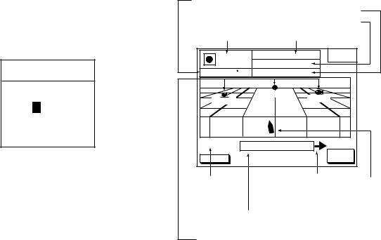
2. PLOTTER DISPLAYS
2.8Steering Display
The steering display provides steering information such as range, bearing, ETA to destination, course and speed.
Press the [XTE/HIWAY] key several times to show the steering display.
Course
Compass bearing
Estimated time of arrival
Speed
Range from own ship to waypoint
Waypoint name
Bearing from |
Course indicator |
|
own ship to |
||
Bearing to waypoint |
||
waypoint |
||
|
|
0 0 1 - W P |
CROSS |
||
|
TRACK |
|||
230 |
240 |
|
250 |
260 |
BRG 2 4 7 . 0 ° |
RNG |
2 7 . 2 n m |
||
CSE 2 4 5 . 0 ° |
SPD |
1 3 . 6 k t |
||
TTG |
1h 59m |
ETA |
29th 14:50 |
|
0.1nm |
XTE |
000.02nm |
0.1nm |
|
|
EDIT |
|||
DGPS 3D |
|
|
|
|
|
|
|
XT-LMT |
|
XTE scale |
Indicates the |
Own ship |
|
direction to steer |
|
|
(Right: green, Left: red) |
|
XTE
indication Amount of XTE in nautical miles range
Time-to-go to waypoint
Steering display
How to read the compass display
The solid inverted triangle at the center of the compass shows own ship’s course. The hollow inverted triangle shows the bearing to destination waypoint. When own ship’s course is changed, the hollow inverted triangle moves with course change.
Note: Course means the direction which own ship moves to, it is different from the own ship’s heading. Tide current and wind may affect the course.
2-7
2. PLOTTER DISPLAYS
How to read the XTE indication
The black boat-shaped mark shows own boat’s movement and direction, and the amount to steer to return to course. Using the figure shown on the previous page as an example, you would steer right by 000.02 nautical miles to return to course. When this mark is out of range of the XTE scale, the mark color changes from black to yellow. The range of the XTE scale can be set as shown below.
Setting the range of the XTE scale
1.Press the EDIT XT-LMT soft key to display the following window.
EDIT XTE LIMIT
0 .1nm
XTE range setting window
2.Use the cursor pad to select digit to change.
3.Press appropriate alphanumeric key.
4.Press the [ENTER] key. To cancel entry, press the CANCEL soft key instead of the [ENTER] key.
Note that all digits may be cleared by pressing the [CLEAR] key.
2.9Highway Display
The highway display provides a graphic presentation of ship’s course. It is useful for monitoring XTE - the XTE scale shows direction and amount in nautical miles to steer to return to course. In the figure below, for example, you would steer right by 0.02 nm to return to course.
Press the [XTE/HIWAY] key once or twice to show the highway display.
Course |
Speed |
|
|
Waypoint mark |
Range to waypoint |
|
|
& name |
Bearing to waypoint |
001WPT |
BRG |
9 4 . 6 ° |
HIGHWAY |
|
RNG |
1 . 8 8 n m |
|
||
CSE 87.8 |
|
SPD |
10.0 kt |
|
|
|
WPT001 |
|
|
YUUKI |
|
|
FISH01 |
|
|
|
|
|
|
0.1nm |
XTE |
0.02nm |
0.1nm |
|
|
EDIT |
|||
DGPS 3D |
|
|
|
|
|
|
|
XTLMT |
|
XTE |
Indicates the |
Own ship |
|
direction to steer |
|||
scale |
|||
(Right: green, Left: red) |
|||
|
|||
|
Amount of XTE in nautical miles |
||
Waypoint
Highway display
2-8
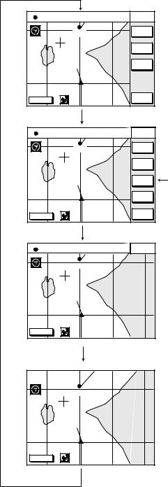
2.10Changing Operation Mode
Operation mode can be changed among PLEASURE, FISHING1 and FISHING2. FISHING1 or 2 mode provides mark/line entry at the cursor or own ship’s position. On FISHING 1 or 2 mode, pressing the [HIDE/SHOW] key changes the function of soft keys. Holding track, changing track color, and selecting color and form of mark/line can be performed by the soft keys directly. For detailed FISHING mode information, see Chapter 4.
2. PLOTTER DISPLAYS
34° |
12.345' N |
CSE |
245.8° |
COURSE |
135° 12.345' E |
SPD |
16.3kt |
UP |
|
|
QP<01> |
|
ZOOM |
|
|
|
IN |
||
|
|
|
|
ZOOM |
|
|
|
|
OUT |
|
|
|
|
AUTO |
|
|
|
|
C.U. |
DGPS 3D |
|
|
|
NAV |
|
|
|
WPT |
|
Press the [HIDE/SHOW] key.
34° |
12.345' N |
CSE |
245.8° |
COURSE |
135° 12.345' E |
SPD |
16.3kt |
UP |
|
|
QP<01> |
|
STOP |
|
|
|
TRACK |
||
|
|
|
|
TRACK |
|
|
|
|
COLOR |
|
|
|
|
MARK |
|
|
|
|
ENTRY |
|
|
|
|
MARK |
|
|
|
|
EDIT |
DGPS 3D |
|
|
|
NAV |
|
|
|
WPT |
|
Press the [HIDE/SHOW] key.
34° |
12.345' N |
CSE |
245.8° |
COURSE |
135° 12.345' E |
SPD |
16.3kt |
UP |
|
|
QP<01> |
|
|
|
DGPS 3D |
|
|
|
|
Soft key to enter marlk.
Press the [HIDE/SHOW] key.
QP<01>
DGPS 3D
Press the [HIDE/SHOW] key.
Sequence of pressing the [HIDE/SHOW] key at FISHING 1 or 2 mode
2-9

2. PLOTTER DISPLAYS
Selecting fishing 1 or fishing 2 mode
1.Press the [MENU] key and the DISPLAY OPTIONS soft key. The display setup1 menu appears.
RNG & BRG MODE |
RHUMB LINE |
DISPLAY |
|
SETUP1 |
|||
RANGE/SPEED UNIT |
nm / kt |
||
|
|||
DEPTH UNIT |
ft |
|
|
TEMP UNIT |
° F |
EDIT |
|
LAT/LON DISPLAY |
DD° MM.MMM' |
|
|
TIME DISPLAY |
24 HOUR |
|
|
WAYPOINTS SW |
AUTO2 |
|
|
COURSE VECTOR |
LINE |
|
|
BEARING |
MAGNETIC |
|
|
MAG VARIATION |
AUTO 01.3° E |
|
|
TD DISPLAY |
LORAN C |
|
|
POSITION DISPLAY |
LAT/LON |
|
|
SET GO TO METHOD |
1 POINT |
|
|
OPERATION MODE |
PLEASURE |
|
|
LANGUAGE |
ENGLISH |
|
|
|
|
RETURN |
|
DGPS 3D |
|
|
Display setup1 menu
2.Press ▼ to select OPERATION MODE.
3.Press the EDIT soft key to show the OPERATION MODE window.
OPERATION MODE
 PLEASURE
FISHING 1
 FISHING 2
Operation mode window
4.Press ▲ or ▼to select PLEASURE, FISHING1 or FISHING2.
5.Press the ENTER soft key or the [ENTER] key to finish.
2.11 Navigation Trip Distance
The navigation trip distance is displayed on the navigation data display. Press the [PLOT] key several times to show the navigation data display.
|
|
|
Trip |
|
DATE: OCT 21 2000 |
TIME 23:59:59 |
LAT/LON |
||
POSITION |
|
|
TRIP: 4792 nm |
|
34° |
56.789' N LONLAT |
|||
135° |
56.789' E |
|||
SPD |
|
|
RNG |
TD |
|
|
|
||
12.5 |
kt |
|
123.25 nm |
|
CSE |
|
|
BRG |
ZOOM |
359.9° |
|
299.9° |
|
|
DATUM: WGS-84 |
|
|
SAT |
|
|
|
|
|
INFO |
TMP 65.8° F |
DEP 20.8ft |
BEACON |
||
|
|
|
|
|
DGPS 3D |
|
|
|
INFO |
Navigation data display
Note: When you enlarge POSITION, TRIP is not displayed.
Resetting trip distance
1.Press the [MENU] key followed by the CONFIGURATION and SYSTEM MENU soft keys.
2.Press the MEMORY/TRIP CLEAR soft key to open the clear memory menu.
CLEAR PLOTTER MEMORY NO |
CLEAR |
MEMORY |
CLEAR GPS MEMORY |
NO |
EDIT |
|
|
CLEAR ALL MEMORY |
NO |
TRIP METER RESET |
NO |
DGPS 3D |
|
|
|
RETURN |
|
|
|
|
Clear memory menu
3.Press ▼to select TRIP METER RESET.
4.Press the EDIT soft key.
5.Press ▲ to select YES.
6.Press the ENTER soft key or the [ENTER] key to reset trips distance.
2-10
3. TRACK
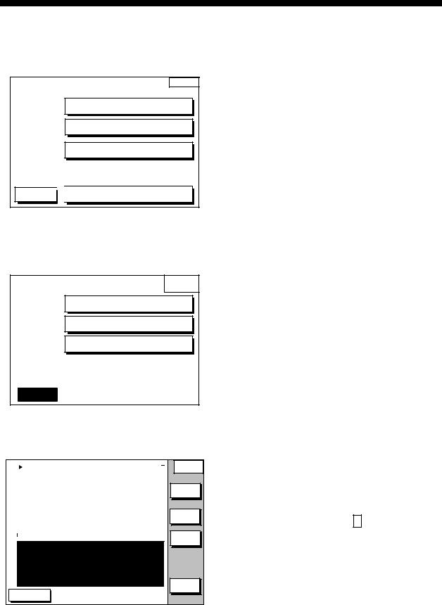
3.1Displaying Track
1.Press the [MENU] key to open the main menu.
MENU
CHART SETUP OPTIONS
DISPLAY OPTIONS
GPS/DGPS/TD OPTIONS
DGPS 3D 
 CONFIGURATION
Main menu
2.Press the CHART SETUP OPTIONS soft key to open the CHART SETUP OPTIONS menu.
CHART
SETUP
CHART OFFSET
TRACK CONTROL
CHART DETAILS
|
|
RETURN |
|
DGPS 3D |
|
|
|
|
|
|
|
Chart setup menu
3.Press the TRACK CONTROL soft key to open the TRACK CONTROL menu.
|
DISPLAY TRACK |
ON |
|
|
|||
|
TRACK COLOR |
|
WHITE |
|
PLOT |
|
TIME |
|
TIME INTERVAL |
01m00s |
|
|
DIST INTERVAL |
|
00.10 nm |
|
TRACK MEMORY |
2000 POINTS |
|
|
(MARK MEMORY) (3000) POINTS |
||
|
|
|
|
|
TRACK STATUS |
|
|
|
TRACKING |
||
|
TRACK : 1000 / 2000 PTS used |
||
|
MARK : |
5 / 3000 PTS used |
|
DGPS 3D
TRACK CONTROL
EDIT |
STOP |
TRACK |
ERASE
T & M
RETURN |
Track control menu
4.Press ▲ to select DISPLAY TRACK.
5.Press the EDIT soft key to show the display track window.
6.Press ▲ or ▼ to select ON or OFF as appropriate.
7.Press the ENTER soft key or the [ENTER] key.
8.Press the [PLOT] key to close the menu.
The default setting is ON, which traces ship’s track in accordance with ship’s movements.
Number of track and mark points used appears in the TRACK STATUS window on the TRACK CONTROL display. Using the illustration at the bottom of the page as an example, it shows that 1000 out of 2000 track points and 5 out of 3000 mark shave been used.
3.2Stopping/Restarting Plotting of Track
When your boat is at anchor or returning to port you probably won’t need to record its track. You can stop recording the track, to conserve the track memory, as follows:
1.Press the [MENU] key followed by the CHART SETUP OPTIONS and TRACK CONTROL soft key.
2.Press the STOP TRACK soft key. The indication “TRACKING” in the TRACK STATUS window changes to “NOT TRACKING”.
On the plotter display, H icon appears.
To restart recording the track, press the START TRACK soft key at step 2 in the above procedure.
3-1
3. TRACK
When the fishing mode is selected, you can stop or restart plotting the track with the soft key only on the plotter display. Press the [HIDE/SHOW] key several times to show the STOP TRACK soft key on the plotter display. Press the STOP TRACK soft key to stop plotting of track. The message of HOLD TRACK PLOTTING appears approx. 2 seconds and then own ship mark changes to hollow circle. To restart plotting the track, press the START TRACK soft key again. The message START TRACK PLOTTING appears approx. 2 seconds and then plotting restarts.
3.3Changing Track Color
Track can be displayed in red, yellow, green, light-blue, purple, blue or white. It can be useful to change track color to discriminate between previous day's track, past track, etc.
1.Press the [MENU] key followed by the CHART SETUP OPTIONS and TRACK CONTROL soft keys.
2.Press ▲ or ▼ to select TRACK COLOR.
3.Press the EDIT soft key to display the TRACK COLOR window.
TRACK COLOR
▲
 RED YELLOW GREEN LIGHT BLUE PURPLE BLUE
WHITE
▼
Track color window
4.Press ▲ or ▼ to select the color desired.
5.Press the ENTER soft key to finish.
When the fishing mode is selected, you can change track color with the soft key only on the track display.
1.Press the [HIDE/SHOW] key several times to show the TRACK COLOR soft key on the plotter display.
2.Press the TRACK COLOR soft key to show the TRACK COLOR window.
3.Press ▲ or ▼ to select the color desired.
4.Press the ENTER soft key or the [ENTER] key to finish, or press the CANCEL soft key to escape.
3.4Track Plotting Method, Interval
In drawing the track, first the ship’s position (fed from the DGPS/GPS receiver, WAAS) is stored into the unit’s memory at an interval of time or distance. A shorter interval provides better reconstruction of the track, but the storage time of the track is reduced. When the track memory becomes full, the oldest track is erased to make room for the latest.
Track plotting method
1.Press the [MENU] key followed by the CHART SETUP OPTIONS and TRACK CONTROL soft keys.
2.Press ▲ or ▼ to select PLOT.
3.Press the EDIT soft key to display the PLOT window.
PLOT
▲
 TIME
TIME
DISTANCE
▼
Plot window
4.Press ▲ or ▼ to select TIME or DISTANCE. Distance is useful for conserving track memory, since no track is recorded when the boat is stationary.
5.Press the ENTER soft key or the [ENTER] key.
3-2
Track plotting interval
1.Press the [MENU] key followed by the CHART SETUP OPTIONS and TRACK CONTROL soft keys.
2.Press ▲ or ▼ to select TIME INTERVAL or DIST INTERVAL.
3.Press the EDIT soft key to display the INTERVAL window.
TIME INTERVAL
01 m 00 s
(When selecting TIME INTERVAL.)
DIST INTERVAL
00.10 nm
(When selecting DIST INTERVAL.)
Interval window
4.Use the cursor pad to place the cursor on the digit desired. The [CLEAR] key functions to clear an entire line of data.
5.Press appropriate alphanumeric key to enter value.
6.Repeat steps 4 and 5 to complete.
7.Press the ENTER soft key or the [ENTER] key.
3.5Changing Track Memory Capacity
The equipment stores a total of 5000 points of track and marks. This total may be freely apportioned as desired. The default setting is 2000 points for track and 3000 points for mark. Note that when the track memory capacity is changed, all tracks and marks in the memory are erased.
1.Press the [MENU] key followed by the CHART SETUP OPTIONS and TRACK CONTROL soft keys.
2.Press ▼ to select TRACK MEMORY.
3. TRACK
3.Press the EDIT soft key to display the TRACK MEMORY window.
TRACK MEMORY
1000/5000 POINTS
Track memory window
The track memory window may be erased by pressing the CANCEL soft key to escape.
4.Enter number of track memory points desired, with the alphanumeric keys.
Note that all digits may be cleared by pressing the CLEAR soft key or the [CLEAR] key.
5.Press the ENTER soft key or the [ENTER] key. The following window appears to ask you if you are sure to change the track memory capacity.
RESETTING ERASES
TRACK, MARK/LINE
ALREADY SAVED. OK?
YES ... "ENTER" key
NO ... "CLEAR" key
Erase message
6.Press the [ENTER] key to change apportion, or press the [CLEAR] key to escape.
3-3
3. TRACK
3.6Erasing Tracks
Be absolutely sure you want to erase track; erased track cannot be restored.
Erasing tracks by area
You can erase tracks within an area you set.
1.Press the [MENU] key followed by the CHART SETUP OPTIONS, TRACK CONTROL and ERASE T & M soft keys.
ERASE ALL TRACKS |
ERASE |
||
ERASE TRACKS BY AREA |
|
||
ERASE TRACKS BY COLOR |
EDIT |
||
ERASE ALL MARKS/LINES |
|||
|
|||
ERASE MARKS BY AREA |
|
||
TRACK STATUS |
|
|
|
TRACKING |
|
||
TRACK : 1000 / 2000 PTS used |
|
||
MARK : |
5 / 3000 PTS used |
RETURN |
|
|
|
||
DGPS 3D |
|
|
|
Erase menu
2.Select ERASE TRACK BY AREA, and then press the EDIT soft key.
3.Move the cursor to the starting point of the area to erase.
4.Press the START soft key.
5.Move the cursor to the ending point of the area to erase.
6.Press the END soft key. You are asked if you sure to erase.
7.Press the [ENTER] key to erase, or press the [CLEAR] key to escape.
Erasing tracks by color
Tracks can be erased by on color.
1.Press the [MENU] key followed by the CHART SETUPOPTIONS, TRACK CONTROL and ERASE T & M soft key.
2.Select ERASE TRACK BY COLOR, and then press the EDIT soft key.
3.Select the color which you want to erase.
4.Press the ENTER soft key or [ENTER] key. You are asked if you are sure to erase.
5.Press the [ENTER] key to erase, or press the [CLEAR] key to escape.
Erasing all track
You can erase all track.
1.Press the [MENU] key followed by the CHART SETUP OPTIONS, TRACK CONTROL and ERASE T& M soft keys.
2.Select ERASE ALL TRACKS, and then press the EDIT soft key.
You are asked if you sure to erase all track.
3.Press the [ENTER] key to erase, or press the [CLEAR] key to escape.
3-4
4. MARK
You can enter marks to denote important locations, such as a good fishing spot. In the default condition, you may enter 3000 marks.
4.1Entering Marks
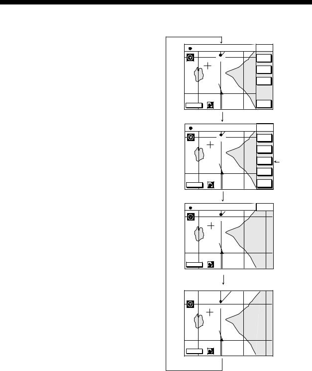
Select the FISHING 1 or FISHING 2 mode to enable entry of marks on the PLOTTER display. Select the location desired with the cursor, or turn off the cursor to enter the mark at own ship position. Press the MARK ENTRY soft key to enter the mark. The mark is entered in the shape and color selected from the MARK SHAPE and MARK COLOR windows.
In the FISHING 1 or FISHING 2 mode, pressing the [HIDE/SHOW] key changes the function of the soft keys as follows.
Plotter display
34° |
12.345' N |
CSE |
245.8° |
COURSE |
135° 12.345' E |
SPD |
16.3kt |
UP |
|
|
QP<01> |
|
ZOOM |
|
|
|
IN |
||
|
|
|
|
ZOOM |
|
|
|
|
OUT |
|
|
|
|
AUTO |
|
|
|
|
C.U. |
DGPS 3D |
|
|
|
NAV |
|
|
|
WPT |
|
Press the [HIDE/SHOW] key.
34° |
12.345' N |
CSE |
245.8° |
COURSE |
|
135° 12.345' E |
SPD |
16.3kt |
UP |
|
|
|
QP<01> |
|
STOP |
|
|
|
|
TRACK |
|
||
|
|
|
|
TRACK |
|
|
|
|
|
COLOR |
|
|
|
|
|
MARK |
Soft key |
|
|
|
|
ENTRY |
|
|
|
|
|
MARK |
to enter mark. |
|
|
|
|
|
|
|
|
|
|
EDIT |
|
DGPS 3D |
|
|
|
NAV |
|
|
|
|
WPT |
|
|
Press the [HIDE/SHOW] key.
34° |
12.345' N |
CSE |
245.8° |
COURSE |
135° 12.345' E |
SPD |
16.3kt |
UP |
|
|
QP<01> |
|
|
|
DGPS 3D |
|
|
|
|
Press the [HIDE/SHOW] key.
QP<01>
DGPS 3D
Press the [HIDE/SHOW] key.
Changing displays (PLOTTER display)
4-1
Loading...