


 Loading...
Furuno 1823C, GD-1900C, 1933C, 1943C, 1953C User Manual
...Back
MARINE RADAR MODEL1823C MARINE RADAR MODEL1833C MARINE RADAR MODEL1933C MARINE RADAR MODEL1943C MARINE RADAR MODEL1953C
COLOR VIDEO PLOTTER GD-1900C
PRINTED IN JAPAN

9-52 Ashihara-cho,
Nishinomiya 662-8580, JAPAN
Telephone : 0798-65-2111
Fax |
: 0798-65-4200 |
All rights reserved. |
Printed in Japan |
Pub. No. IME-35030-P
( AKMU ) M1803C SER & GD1900C
The paper used in this manual is elemental chlorine free.
Your Local Agent/Dealer
FIRST EDITION : APR. 2001
P : MAY. 20, 2005
*00080919906*
*00080919906*
* 0 0 0 8 0 9 1 9 9 0 6 *
*IME35030P00*
*IME35030P00*
* I M E 3 5 0 3 0 P 0 0 *

 SAFETY INSTRUCTIONS
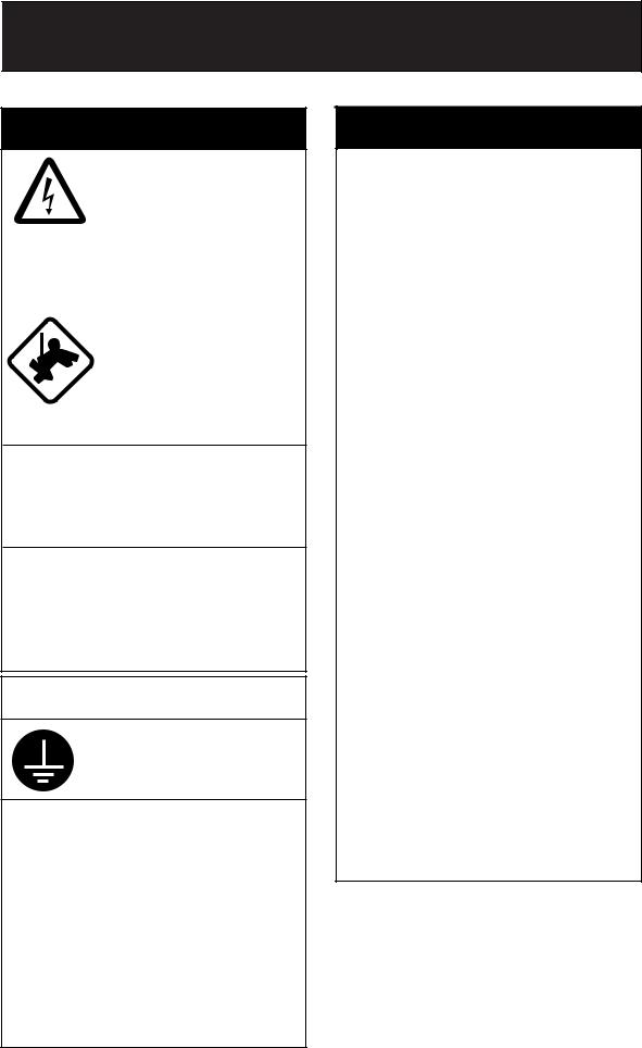
 WARNING
|
Do not open the equipment |
|
|
unless totally familiar with |
|
|
electrical circuits and |
|
|
service manual. |
|
ELECTRICAL |
Only qualified personnel |
|
should work inside the |
||
SHOCK |
||
HAZARD |
equipment. |
|
|
|
|
|
Wear a safety belt and hard |
|
|
hat when working on the |
|
|
antenna unit. |
Serious injury or death can result if someone falls from the radar mast.
Construct a suitable service platform from which to install the antenna unit.
Serious injury or death can result if someone falls from the radar mast.
Turn off the power at the mains switchboard before beginning the installation.
Fire, electrical shock or serious injury can result if the power is left on or is applied while the equipment is being installed.
 CAUTION
Ground the equipment to prevent electrical shock and mutual interference.
Observe the following compass safe distances to prevent deviation of a magnetic compass.
|
Standard |
Steering |
|
|
|
|
|
Display unit |
0.60 m |
0.40 m |
|
MODEL1823C antenna unit |
1.25 m |
0.85 m |
|
MODEL1833C antenna unit |
0.90 m |
0.70 m |
|
MODEL1933C antenna unit |
1.00 m |
0.80 m |
|
MODEL1943C antenna unit |
1.00 m |
0.80 m |
|
MODEL1953C antenna unit |
1.00 m |
0.75 m |
|
Power supply unit (1953C) |
1.40 m |
0.95 m |
|
Memory card IF unit |
0.90 m |
0.60 m |
|
(option) |
|||
|
|
||
|
|
|
 WARNING
Radio Frequency
Radiation Hazard
The radar antenna emits electromagnetic radio frequency (RF) energy which can be harmful, particularly to your eyes. Never look directly into the antenna aperture from a close distance while the radar is in operation or expose yourself to the transmitting antenna at a close distance.
Distances at which RF radiation levels of 100 and 10 W/m2 exist are given in the table below.
Note: If the antenna unit is installed at a close distance in front of the wheel house, your administration may require halt of transmission within a certain sector of antenna revolution. This is possible - Ask your FURUNO representative or dealer to provide this feature.
MODEL |
Distance to |
Distance to |
||
100 W/m2 |
10 W/m2 |
|||
|
|
point |
point |
|
|
|
|
|
|
MODEL |
Nil |
Worst case |
||
1823C |
0.50 m |
|||
|
||||
|
|
|
||
MODEL |
Nil |
Worst case |
||
1833C |
0.50 m |
|||
|
||||
|
|
|
|
|
MODEL |
Nil |
Worst case |
||
1933C |
3.00 m |
|||
|
||||
|
|
|
|
|
MODEL |
Nil |
Worst case |
||
1943C |
2.50 m |
|||
|
||||
|
|
|
|
|
|
XN12A |
|
Worst case |
|
MODEL |
|
2.50 m |
||
|
Nil |
|||
1953C |
XN13A |
Worst case |
||
|
||||
|
|
|||
|
|
2.30 m |
||
|
|
|
||
|
|
|
|
|
i
TABLE OF CONTENTS
|
|
|
........................................................................................SAFETY INSTRUCTIONS |
i |
|
EQUIPMENT LISTS ................................................................................................. |
iii |
|
SYSTEM CONFIGURATIONS.................................................................................. |
v |
|
1. MOUNTING .......................................................................................................... |
1-1 |
|
1.1 |
Installation of Display Unit .......................................................................................................... |
1-1 |
1.2 |
Mounting of Antenna Unit for MODEL1833C............................................................................... |
1-4 |
1.3 |
Mounting of Antenna Unit for MODEL1933C/1943C/1953C ........................................................ |
1-11 |
1.4 |
Mounting of Power Supply Unit for MODEL1953C...................................................................... |
1-20 |
1.5 |
Mounting of Antenna Unit for MODEL1823C............................................................................... |
1-21 |
2. WIRING ................................................................................................................ |
2-1 |
|
2.1 |
Standard Wiring ......................................................................................................................... |
2-1 |
2.2 |
External Buzzer (OP03-136, option) Connection......................................................................... |
2-4 |
2.3 |
How to Connect with PC ........................................................................................................... |
2-5 |
2.4 Wiring of Power Supply Unit (MODEL1953C only)...................................................................... |
2-6 |
|
2.5 |
Connection of CU-200 (option) ................................................................................................... |
2-8 |
3. ADJUSTMENT ..................................................................................................... |
3-1 |
|
3.1 |
How to Access to Installation Menu ............................................................................................ |
3-1 |
3.2 NETWORK SETUP Menu .......................................................................................................... |
3-2 |
|
3.3 RADAR SETUP Menu................................................................................................................ |
3-4 |
|
3.4 |
Checking Magnetron Heater Voltage .......................................................................................... |
3-11 |
3.5 |
Navigation Data Source ............................................................................................................. |
3-11 |
3.6 |
Setting up Data Ports ................................................................................................................. |
3-16 |
3.7 |
Remote Controller Setting .......................................................................................................... |
3-18 |
3.8 |
Remote Display Setting.............................................................................................................. |
3-19 |
4. OPTIONS.............................................................................................................. |
4-1 |
|
4.1 ARP Kit ARP-11.......................................................................................................................... |
4-1 |
|
4.2 |
Connection of Video equipment/External Monitor/Remote Display .............................................. |
4-4 |
4.3 |
Mounting the Memory Card Interface Unit .................................................................................. |
4-10 |
PACKING LISTS ...................................................................................................... |
A-1 |
|
OUTLINE DRAWINGS ............................................................................................. |
D-1 |
|
INTERCONNECTION DIAGRAMS........................................................................... |
S-1 |
|
ii

EQUIPMENT LISTS
Standard supply
Name |
Type |
Code No. |
Qty |
Remarks |
|
Display unit |
RDP-138* |
- |
1 |
Normal bright LCD, 300 Cd |
|
RDP-139 |
- |
High bright LCD, 700 Cd |
|||
|
|
||||
|
RSB-0094-0075 |
- |
|
MODEL 1823C |
|
|
RSB-0071-057 |
- |
|
MODEL 1833C |
|
|
XN10A-RSB-0070-064 |
- |
|
MODEL1933C, |
|
|
|
24 rpm, for RDP-138/139 |
|||
|
|
|
|
||
|
XN10A-RSB-0073-064 |
- |
|
MODEL1933C, |
|
Antenna unit |
1 |
48 rpm, for RDP-138 |
|||
|
|
||||
|
XN12A-RSB-0070-059 |
- |
|
MODEL1943C, 24 rpm |
|
|
XN12A-RSB-0073-059 |
- |
|
MODEL1943C, 48 rpm |
|
|
XN12A-RSB-0072-060 |
- |
|
MODEL1953C, 4”, 24 rpm |
|
|
XN12A-RSB-0073-060 |
- |
|
MODEL1953C, 4”, 48 rpm |
|
|
XN13A-RSB-0072-060 |
- |
|
MODEL1953C, 6”, 24 rpm |
|
Power supply unit |
PSU-005 |
- |
1 |
For MODEL1953C |
|
Remote controller |
RMC-100 |
000-089-885 |
1 |
Remote controller, vinyl case, |
|
set |
battery, labels |
||||
|
|
|
|||
|
|
|
|
For display unit, |
|
|
CP03-22700 |
000-080-049 |
1set |
MJ-A3SPF0018-050Z cable, |
|
|
|
|
|
CP03-22701 |
|
|
CP03-25401 |
008-443-160 |
1set |
For MODEL1823C |
|
|
antenna unit |
||||
|
|
|
|
||
|
CP03-16901 |
008-478-750 |
1set |
For MODEL1833C |
|
|
antenna unit |
||||
|
|
|
|
||
|
CP03-21800 |
000-080-014 |
|
For MODEL1823C/1833C |
|
|
|
10 m signal cable |
|||
|
|
|
|
||
|
CP03-21810 |
000-080-015 |
|
For MODEL1823C/1833C |
|
|
1 |
15 m signal cable |
|||
|
|
|
|||
|
CP03-21820 |
000-080-016 |
For MODEL1823C/1833C |
||
|
|
||||
|
|
20 m signal cable |
|||
Installation |
|
|
|
||
CP03-21830 |
000-080-017 |
|
For MODEL1823C/1833C |
||
materials |
|
30 m signal cable |
|||
|
|
|
|||
|
CP03-22000 |
000-080-021 |
|
For 1933C/1943C/1953C |
|
|
|
10 m signal cable |
|||
|
|
|
|
||
|
CP03-22010 |
000-080-022 |
|
For 1933C/1943C/1953C |
|
|
1 |
15 m signal cable |
|||
|
|
|
|||
|
CP03-22020 |
000-080-023 |
For 1933C/1943C/1953C |
||
|
|
||||
|
|
20 m signal cable |
|||
|
|
|
|
||
|
CP03-22030 |
000-080-024 |
|
For 1933C/1943C/1953C |
|
|
|
30 m signal cable |
|||
|
|
|
|
||
|
CP03-18401 |
008-503-360 |
1 |
For 1933C/1943C/1953C |
|
|
antenna unit |
||||
|
|
|
|
||
|
CP03-22901 |
008-523-690 |
1 |
For 1933C/1943C/1953C |
|
|
antenna radiator XN10A/XN12A |
||||
|
|
|
|
||
|
CP03-24500 |
000-080-191 |
1 |
For 1953C, power supply unit |
|
Accessories |
FP03-09301 |
008-522-970 |
1set |
Card remover |
|
Spare parts |
SP03-14001 |
000-080-018 |
1set |
Fuses, for display unit |
|
SP03-14001 |
000-080-018 |
1set |
Fuses, for power supply unit |
||
|
(1953C only) |
||||
|
|
|
|
||
|
|
|
|
*Not available for MODEL 1953C |
iii
Optional supply
Name |
Type |
Code No. |
Qty |
Remarks |
|
|
|
000-013-484 |
|
For GD-1900C, 100 VAC |
|
Rectifier |
PR-62 |
000-013-485 |
1 |
For GD-1900C, 110 VAC |
|
000-013-486 |
For GD-1900C, 220 VAC |
||||
|
|
||||
|
|
000-013-487 |
|
For GD-1900C, 230 VAC |
|
|
RU-3423 |
000-030-443 |
1 |
For MODEL series |
|
External buzzer |
OP03-136 |
000-086-443 |
1 |
|
|
|
MJ-A6SPF0014-010 |
000-144-421 |
1 |
For NavNet, 1 m |
|
|
MJ-A6SPF0014-050 |
000-144-422 |
1 |
For NavNet, 5 m |
|
|
MJ-A6SPF0014-100 |
000-144-423 |
1 |
For NavNet, 10 m |
|
|
MJ-A6SPF0014-200 |
000-144-424 |
1 |
For NavNet, 20 m |
|
|
MJ-A6SPF0014-300 |
000-144-425 |
1 |
For NavNet, 30 m |
|
|
MJ-A6SPF0012-050 |
000-134-424 |
1 |
For navaid, 5 m |
|
|
MJ-A6SPF0012-100 |
000-133-817 |
1 |
For navaid, 10 m |
|
Cable assy. |
MJ-A6SPF0003-050 |
000-117-603 |
1 |
w/6P connector, 5 m |
|
MJ-A6SPF0009-100 |
000-125-236 |
1 |
w/6P connector, 10 m |
||
|
|||||
|
MJ-A6SPF0007-100 |
000-125-237 |
1 |
For compass, 10 m |
|
|
MJ-A7SPF0007-050 |
000-144-418 |
1 |
For external buzzer, PC, |
|
|
w/7P connector, 5 m |
||||
|
|
|
|
||
|
MJ-A6SRMD/TM11AP8-005 |
000-144-463 |
1 |
Adapter cable for HUB |
|
|
MJ-B24LPF0008-100 |
000-145-125 |
1 |
For remote display, 10 m |
|
|
MJ-B24LPF0008-200 |
000-145-126 |
1 |
For remote display, 20 m |
|
|
MJ-B24LPF0008-300 |
000-145-127 |
1 |
For remote display, 30 m |
|
RGB output |
OP03-176 |
008-526-360 |
1 |
For external monitor |
|
cable kit |
|||||
|
|
|
|
||
ARP kit |
ARP-11 |
008-523-050 |
1 |
ARP Board, for radar only |
|
NTSC/PAL |
OP03-175 |
008-523-070 |
1 |
Connection video source |
|
interface kit |
|||||
|
|
|
|
||
Mounting |
OP03-92 |
008-445-070 |
1 |
For MODEL1833C |
|
bracket (1) |
|||||
|
|
|
|
||
Mounting |
OP03-93 |
008-445-080 |
1 |
For MODEL1823C |
|
bracket (2) |
|||||
|
|
|
|
||
Chart card |
- |
- |
- |
Specified when ordering. |
|
RAM card |
00RAM02MC-004 |
004-371-790 |
1 |
2 MB |
|
Remote |
RMC-100 |
000-089-885 |
1 |
|
|
controller set |
|
||||
|
|
|
|
||
Modification kit |
MODEL17*2/C-MAP |
008-525-200 |
1 |
See modification instruction |
|
for C-map |
E42-00005-x |
||||
|
|
|
|||
EMI core |
E04R241336A |
000-146-335 |
1 |
For remote display cable connection |
|
Memory card |
CU-200-NAV |
000-081-567 |
1 |
w/two chart card slots |
|
interface unit |
|||||
|
|
|
|
iv

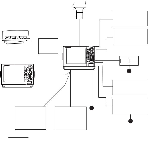
SYSTEM CONFIGURATIONS
All NavNet products incorporate a “network circuit board” to integrate each NavNet product on board through an optional LAN cable (Ethernet 10BASE-T). Each NavNet product is assigned an IP address to enable transfer of images between other NavNet products. For example, video plotter pictures can be transferred to a radar and vice versa. Pictures received via the NavNet may be adjusted at the receiving end.
The number of display units which may be installed depends on the number of network sounder connected. For a system incorporating three or more products, a “hub” is required to process data.
For one network sounder: one radar and three plotters, or four plotters For two network sounder: one radar and two plotters, or four plotters
|
|
Antenna Unit |
MODEL1823C |
|
|
|
|
MODEL |
MODEL |
MODEL |
|
1953C |
1933C |
1943C |
MODEL |
|
|
|
1833C |
GPS receiver GP-310B/320B
Power Supply
Unit PSU-005
Display unit RDP-138*/139
Memory card interface unit CU-200
12 VDC
Rectifier
RU-3423
Facsimile
Receiver
FAX-30
100/110/115/220/230 VAC 12 - 24 VDC**
1φ , 50/60 Hz**
*: Not available for MODEL 1953C.
**: The power for the power supply unit and display unit must be drawn from the same power source.
Network
Sounder
ETR-6/10N
ETR-30N
Echo sounder
Navigator
External buzzer PC
Echo sounder
VGA monitor Remote display Video equipment
Heading
sensor
Other NavNet unit (GD-1900C etc.)
Figure 1 (a) NavNet system (MODEL1823C/1833C/1933C/1943C/1953C)
v

 GPS receiver
 GP-310B/320B
Remote
Controller
RMC-100
Display unit
RDP-138/139
Other NavNet Unit (Model 1833C, etc.)
Facsimile |
Network Sounder 12 - 24 VDC |
Receiver |
ETR-6/10N |
FAX-30 |
ETR-30N |
:Standard
:Option
External buzzer
PC
Echo sounder
VGA monitor
Remote display
Video equipment
Memory card interface unit CU-200
12 VDC
Echosounder
Navigator
Rectifier
PR-62
Ship's mains 100/110/115/220/230 VAC 1φ , 50/60 Hz
Figure 1 (b) NavNet system (GD-1900C)
vi

Figure 2 (a) NavNet system, three-unit connection
Radar Antenna Unit |
Radar Antenna Unit |
OR |
OR |
GPS Receiver GP-310B/320B |
GPS Receiver GP-310B/320B |
RADAR |
RADAR |
or |
or |
PLOTTER |
PLOTTER |
Radar data |
Plotter data |
HUB
Sounder data
Facsimile
data
Sounder data
Note: The picture disappears 10 seconds after the NavNet cable is disconnected from a "sub" NavNet display unit.
Network Sounder |
|
Facsimile |
|
|
|
|
Network Sounder |
||
ETR-6/10N |
|
Receiver |
|
ETR-6/10N |
ETR-30N |
|
FAX-30 |
|
ETR-30N |
(option) |
|
(option) |
|
(option) |
|
|
|
|
|
|
|
|
|
|
|
|
|
|
|
Figure 2 (b) NavNet system, two-unit connection
vii
This page is intentionally left blank.
viii
1.MOUNTING
1.1Installation of Display Unit
The display unit can be installed on a tabletop, on the overhead or flush mounted in a console or panel.
Tabletop, overhead mounting method
When selecting a mounting location for the display unit keep the following in mind:
•Keep the display unit out of direct sunlight.
•The temperature and humidity should be moderate and stable.
•Locate the unit away from exhaust pipes and vents.
•The mounting location should be well ventilated.
•Mount the unit where shock and vibration are minimal.
•Keep the unit away electromagnetic field generating equipment such as motor, generator.
•For maintenance and checking purposes, leave sufficient space at the sides and rear of the unit and leave slack in cables.
•A magnetic compass will be affected if the display unit is placed too close the magnetic compass. Observe the following compass safe distances to prevent disturbance to the magnetic compass.
Standard compass: 0.60 m
Steering compass: 0.40 m
1-1
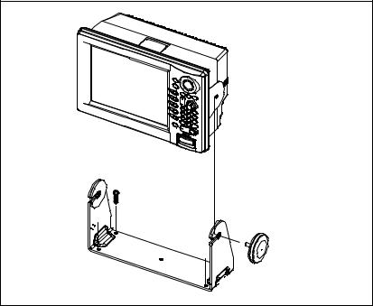
1.1.1Mounting procedure
Tabletop, overhead mounting
Follow the procedure below to mount the display unit on a tabletop or the overhead.
1.Fix the hanger by four tapping screw (5x20).
2.Screw knob bolts in display unit, set it to hanger, and tighten knob bolts.
3.Attach hard cover to protect LCD.
Display unit
Tapping screws (4 pcs.)
Knob bolts (2 pcs.)
Hanger
Tabletop, overhead mounting of display unit
Note: For the overhead mounting, reinforce the mounting location and secure the hanger, with bolts, nuts and washers (local supply).
1-2
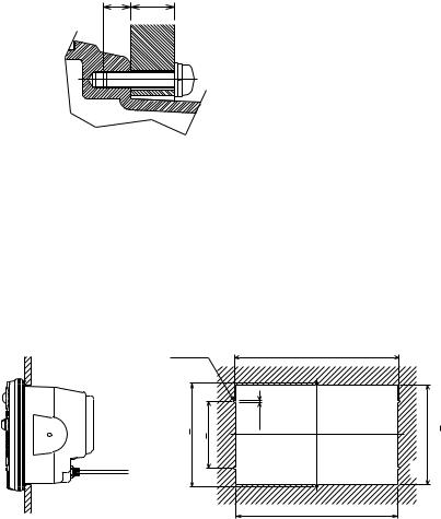
Flush mounting
Note: Use supplied six pan head screws when the thickness of the bulkhead is from 11 to 14 mm. For bulkhead which exceeds 14 mm in thickness the length of the pan head screws should be bulkhead thickness (A) plus 7.8±2 mm. Also the length of B should be max. 8 mm.
B A
A: thickness of bulkhead
Fixing screw, side view
1.Prepare a cutout in the mounting location by using the template sheet supplied as the installation material.
2.Fix the display unit by six washer head screws M4x20. Refer to the outline drawing at back of this manual.
6-R2.25 |
|
342+0.5 |
|
217+0.5 |
140+0.5 |
4.5 |
209+1 |
335+1
Flush mounting of display unit
Note: When installing the display unit in a panel, attach the vinyl tube (Ф6, local supplied) to the drain hole to allow moisture to escape. Then fasten the tube to the drain hole with a cable tie.
1-3
1.2Mounting of Antenna Unit for MODEL1833C
1.2.1Mounting considerations
When selecting a mounting location for the antenna unit keep in mind the following points.
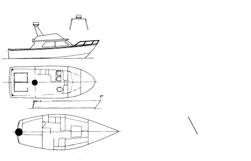
•Install the antenna unit on the hardtop, radar arch or on a mast on an appropriate platform. (For sailboats, a mounting bracket is optionally available.) It should be placed where there is a good all-round view with, as far as possible, no part of the ship’s superstructure or rigging intercepting the scanning beam. Any obstruction will cause shadow and blind sectors. A mast, for instance, with a diameter considerably less than the width of the antenna unit, will cause only a small blind sector. However, a horizontal spreader or crosstrees in the same horizontal plane would be a much more serious obstruction; place the antenna unit well above or below it.
Antenna unit
Antenna unit
Antenna unit
Antenna unit
Typical antenna unit placement on sailboat and powerboat
•In order to minimize the chance of picking up electrical interference, avoid where possible routing the antenna cable near other electrical equipment onboard. Also avoid running the cable in parallel with power cables.
•The compass safe distance of 0.90 meters (standard compass) and 0.70 meters (steering compass) should be observed to prevent deviation of the magnetic compass.
1-4
1.2.2Mounting antenna unit of MODEL 1833C
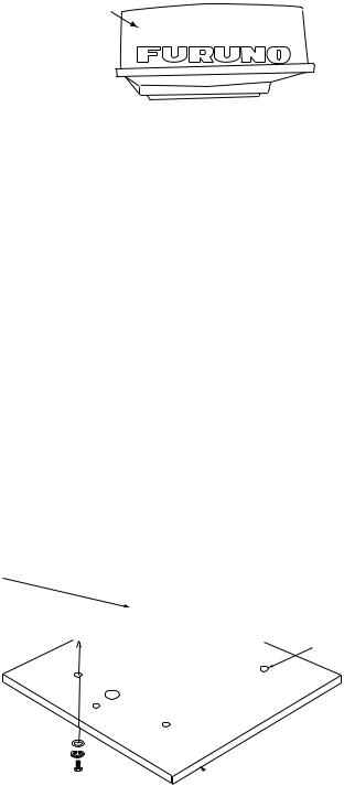
1.Open the antenna unit packing box carefully.
2.Unbolt the four bolts at the base of the radome to remove the radome cover.
Radome cover
Antenna unit
The mounting surface must be parallel with the waterline and provided with five holes (four fixing holes and one cable entry) whose dimensions are shown in the outline drawing attached at the end of this manual.
The unit is adjusted so a target echo returned from the bow direction will be shown on the zero degree (heading line) position on the screen. When drilling holes, be sure they are parallel with the fore and aft line.
3.Prepare a platform of 5 to 10 millimeters in thickness for the antenna unit.
A mounting bracket for mounting the antenna unit on a sailboat mast is optionally available. (Refer to page 1-9.) Find the cable entry on the radome base. Next, position the radome base so the cable entry faces the stern direction. This alignment must be as accurate as possible.
Cable entry
Flat washer  Spring washer
 M10 x 25 Hex bolt
Ship's bow
4- 12 Holes
 Platform
Antenna unit, cover removed
1-5
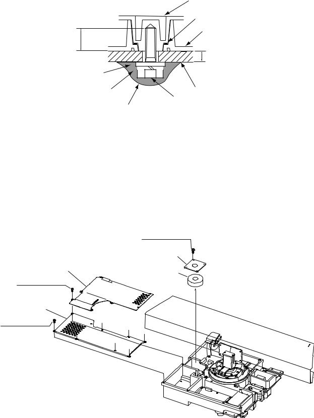
|
Antenna base plate |
|
Effective |
Gasket |
|
thread length |
Radome |
|
|
||
25 mm |
|
|
|
5 - 10 mm |
|
Flat |
|
|
washer |
|
|
Spring |
Platform |
|
washer |
M10 x 25 |
|
Apply silicone sealant. |
||
Hex bolt |
How to fasten the radome base to the mounting platform
Wiring and final preparation
4.Drill a hole of at least 20 millimeters diameter through the deck or bulkhead to run the signal cable between the antenna unit and the display unit. (To prevent electrical interference avoid running the signal cable near other electrical equipment and in parallel with power cables.) Pass the cable through the hole. Then, seal the hole with sealing compound for waterproofing.
5.Remove two shield covers in the radome.
6.Remove the cable clamping plate by unfastening four screws and removing a gasket.
|
Pan head screws |
|
M4x8 4 pcs. |
|
Cable clamping plate |
Shield cover |
Gasket |
|
|
Pan head screws |
|
M4x8 7 pcs. |
|
Shield cover
Pan head screws
M4x8 7 pcs.
Antenna unit, inside view
7.Pass the cable through the hole at the bottom of the radome base.
8.Secure the cable with the cable clamping plate and gasket. Ground the shield wire by one of the screws of the cable clamping plate.
1-6
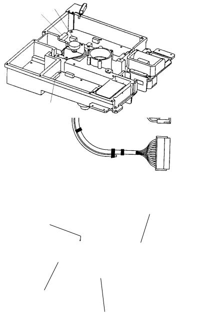
9. Attach three connectors of the signal cable to respective ports as shown below.
to one of the screws
of the cable clamping plate
9-pin connector:
to J801 on MD-9208
4-pin connector:
to J802 on MD-9208
13-pin connector: to J611 on IF-9214
Signal cable, antenna unit side
J801 |
J802 |
MD-9208 |
Cable entry
PTU-9335
J611
IF-9214
RF unit
1-7
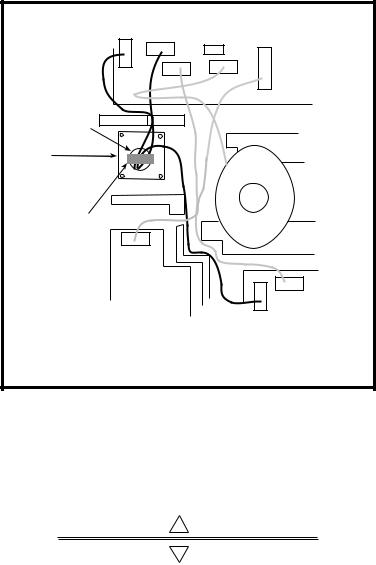
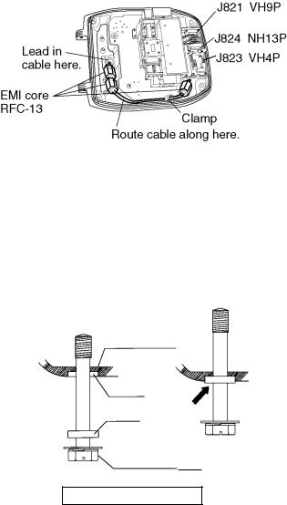
10.Attach the EMI cores supplied as shown below.
J801 |
J802 |
J805 |
MD-9208 |
|
J804
J806
J803
Cable entrance
Cable |
Motor |
|
clamping plate |
||
|
EMI core E04SS251512 (Above cable
clamping J1 plate)
J613
PTU-9335
J611 IF9214A
How to attach EMI core
11.Fix the shield cover. Do not pinch the cable.
12.Attach the radome cover, aligning triangle mark on radome cover with that on radome base.
Radome cover
Radome base
How to position the radome cover
13.Loosely fasten the radome fixing bolts. You will tighten them after confirming magnetron heater voltage.
1-8
1.2.3Mounting the optional mounting bracket
A mounting bracket for fastening the antenna unit for MODEL1833C to a mast on a sailboat is optionally available.
Mounting bracket 1 |
|
|
|
|
|
Type: |
OP03-92 |
|
|
|
|
Code No.: |
008-445-070 |
|
|
|
|
|
|
Table 1-1 Mounting bracket contents |
|
||
|
|
|
|
|
|
|
|
|
Type |
Code No. |
Qty |
|
|
|
|
|
|
|
Hex. bolt |
|
M4X12 |
000-804-725 |
4 |
|
|
|
|
|
|
|
Hex. bolt |
|
M8X20 |
000-805-707 |
8 |
|
|
|
|
|
|
|
Mounting plate |
|
03-018-9001-0 |
100-206-740 |
1 |
|
|
|
|
|
|
|
Support plate (1) |
|
03-018-9005-0 |
100-206-780 |
1 |
|
|
|
|
|
|
|
Support plate (2) |
|
03-018-9006-0 |
100-206-790 |
1 |
|
|
|
|
|
|
|
Bracket (1) |
|
03-018-9002-1 |
100-206-751 |
1 |
|
|
|
|
|
|
|
Bracket (2) |
|
03-018-9003-1 |
100-206-761 |
1 |
|
|
|
|
|
|
|
Fixing plate |
|
03-018-9004-1 |
100-206-771 |
2 |
|
|
|
|
|
|
Assemble the mounting bracket and fasten it to a mast. Fasten the antenna unit to the bracket.
1-9
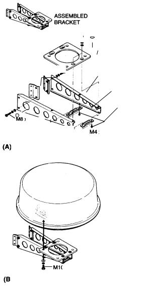
M8 x 20
plate
M8 x 20 |
(1) |
|
plate (2)
Bracket
Support plate (1)
M8 x 20
M4 x 12
(A) Assembling the mounting bracket
M10 x 25 (supplied with antenna unit)
(B)Fastening antenna to mounting bracket
How to assemble and mount the optional mounting bracket
1-10
1.3Mounting of Antenna Unit for MODEL1933C/1943C/1953C
1.3.1Mounting considerations
•The antenna unit is generally installed either on top of the wheelhouse or on the radar mast on a suitable platform. Locate the antenna unit where there is a good all-round view. Any obstruction will cause shadow and blind sectors.
A mast for instance, with a diameter considerably less than the width of the radiator, will cause only a small blind sector, but a horizontal spreader or crosstrees in the same horizontal plane as the antenna unit would be a much more serious obstruction; you would need to place the antenna unit well above or below it.
•It is rarely possible to place the antenna unit where a completely clear view in all directions is available. Thus, you should determine the angular width and relative bearing of any shadow sectors for their influence on the radar at the first opportunity after fitting.
•If you have a radio direction finder on your boat, keep the antenna unit from its antenna more than two meters to prevent the interference to the direction finder.
•To lessen the chance of picking up electrical interference, avoid where possible routing the signal cable near other onboard electrical equipment. Also avoid running the cable in parallel with power cables.
•A magnetic compass will be affected if the antenna unit is placed too close to the magnet compass. Observe the following compass safe distances to prevent deviation of a magnetic compass: Standard compass, 1.00 m, Steering compass, 0.80 m (1953C: 0.75 m).
•Do not paint the radiator aperture, to ensure proper emission of the radar waves.
a)When this radar is to be installed on larger vessels, consider the following points:
The signal cable run between the antenna and the display comes in lengths of 10 m, 15 m, 20 m and 30 m. Whatever length is used it must be unbroken; namely, no splicing allowed.
b)Deposits and fumes from a funnel or other exhaust vent can adversely affect the aerial performance and hot gases may distort the radiator portion. The antenna unit must not be mounted where the temperature is more than 70°C.
As shown in the figure below, the antenna unit may be installed on the bridge, on a common mast or on the radar mast.
(a) On bridge |
(b) Common mast |
(c) Radar mast |
1-11
1.3.2Mounting antenna unit of MODEL 1933C/1943C/1953C
Referring to the outline drawing at the back of this manual, drill five holes in the mounting platform: four holes of 15 mm diameter for fixing the antenna unit and one hole of 25-30 mm diameter for the signal cable.
Fastening the Radiator to the Radiator Bracket
For your reference, antenna installation materials list appears in the packing lists at the back of this manual (see page A-6 to A-11).
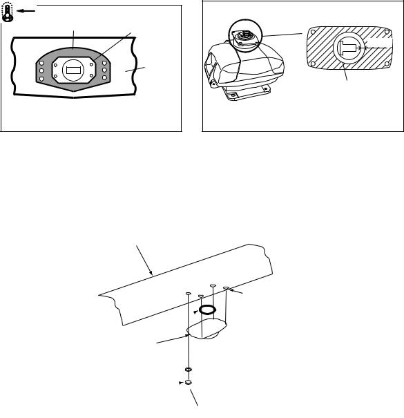
1.Remove the radiator cap from the radiator bracket.
2.Coat contacting surface between antenna radiator and radiator bracket with silicone sealant as shown in figure below.
ANTENNA RADIATOR |
|
RADIATOR BRACKET |
|
(top view) |
|
(bottom view) |
|
|
Groove |
|
|
|
|
|
|
|
10mm |
|
Radiator |
|
|
|
Coat hatched area with |
Coat hatched area with |
anticorrosive sealant. |
|
|
||
silicone sealant. |
|
|
(MODEL 1933C) |
|
(MODEL 1943C/1953C) |
Coating the antenna with silicone sealant
3.Coat threaded holes on the antenna radiator with silicone sealant.
4.Grease the O-ring and set it to the radiator bracket.
5.Lay the antenna radiator on the radiator bracket.
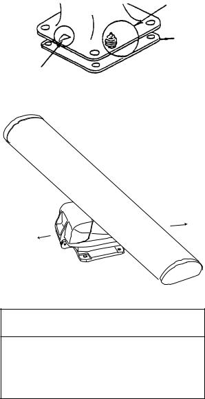
6.Coat the radiator fixing bolts (4 pcs.) with silicone sealant. Fasten the antenna radiator to the radiator bracket with the radiator fixing bolts, flat washers and spring washers.
Antenna radiator
O-ring 
 Radiator bracket
Flat washer 
 Spring washer
 Hex head bolt
 (M8 x 30)
Coat threaded holes with silicone sealant.
Coat bolts with silicone sealant.
Fastening the radiator bracket to the antenna unit chassis
1-12
Mounting of antenna unit
The antenna unit can be mounted using the fixing holes on the outside (200 x 200 mm) or inside (140 x 150 mm) the antenna unit.
Outside fixing holes
Use the hex head bolt (supplied) to mount the antenna unit as below.
1. Lay the corrosion-proof rubber mat (supplied) on the mounting platform.
Ground terminal
Rubber mat
Bow mark
Location of rubber mat
2. Lay the antenna unit on the mounting platform, orienting it as shown in below.
BOW
STERN
Antenna unit
 CAUTION
Do not lift the Antenna unit by the radiator; lift it by the housing.
The radiator may be damaged.
3.Insert four hex bolts (M12x60, supplied) and seal washers (Ф30, supplied) from the top of the antenna housing. Insert the seal washers with the larger diameter next to the bolt heads.
1-13

Hex bolt
Seal washer
Flat washer
Spring washer
Nut
Fixing the antenna unit chassis
4.Pass flat washers (M12, supplied), spring washers (M12, supplied) and nuts (M12, supplied) onto hex bolts. Fasten by tightening nuts. Do not fasten by tightening the hex bolts; seal washers may be damaged.
Seal washer |
|
|
|
Antenna |
|
Rubber mat |
unit |
|
Mounting |
||
|
||
|
platform |
|
Flat washer |
Silicone |
|
|
sealant |
How to fasten antenna unit to mounting platform
5.Coat flat washers, spring washers, nuts and exposed parts of bolts with anticorrosive sealant.
6.Prepare ground point in mounting platform (within 300 mm of ground terminal on antenna unit) using M6 x 25 bolt, nut and flat washer (supplied).
7.Run the ground wire (RW-4747, 340 mm, supplied) between the ground terminal and ground point.
8.Coat ground terminal and ground point with silicone sealant as shown on the next page.
1-14
|
|
Hex bolt |
|
|
|
Flat washer |
|
Ground |
|
Flat washer |
|
wire |
|
||
|
Spring washer |
||
|
|
||
Silicone |
|
Hex nut |
|
OR |
|
|
|
sealant |
|
GROUND |
|
|
|
||
|
|
|
POINT |
Ground |
|
Hex nut |
|
|
Spring washer |
||
wire |
|
||
|
Flat washer |
||
|
|
||
|
|
Hex nut |
|
Weld here.
GROUND
TERMINAL
Silicone sealant
Ground wire
antenna unit
How to coat ground point and ground terminal with silicone sealant
1-15
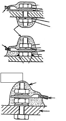
Fixing holes inside antenna unit
This method requires removal of the RF unit in the antenna unit to access inside fixing holes. Use hex head bolts, flat washers, spring washers and nuts (local supply) to mount the antenna unit, confirming length of bolts.
1.Loose four scanner bolts to open the antenna unit.
Refer to figure in below for locations.
Antenna unit chassis, upper chassis separated
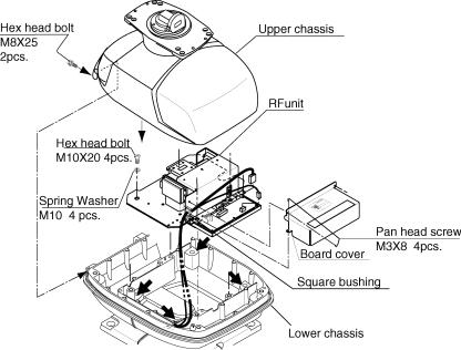
2.Unplug connector connected between upper and lower chassis.
3.Separate upper chassis from lower chassis by removing two hex head bolts (M8x25).
4.Remove the board cover by unfastening four pan head screws.
5.Remove connector from RF unit.
6.Remove RF unit by unfastening four hex head bolts.
7.Lay the corrosion-proof rubber mat (supplied) on the mounting platform.
8.Fasten the lower chassis to the mounting platform with hex head bolts, spring washers, flat washers and nuts (local supply), and then coat flat washers, nuts and exposed parts of bolts with silicone sealant. Cut a slit in rubber bushing and insert bolt into bushing. Do not use seal washers.
9.Reassemble RF unit, cover and chassis.
10.Set four knob caps (supplied) into outside fixing holes.
11.Do steps 6-8 in “Outside fixing holes”.
1-16
Connecting the Signal Cable
Only the signal cable runs from the display unit (1953C: power supply unit) to the antenna unit. In order to minimize the chance of picking up electrical interference, avoid where possible routing the signal cable near other onboard electrical equipment. Also, avoid running the cable in parallel with power cables. Pass the cable through the hole and apply sealing compound around the hole for waterproofing.
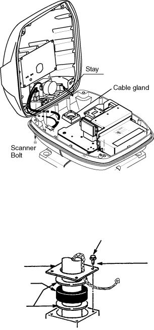
1. Open the antenna cover by loosening four scanner bolts, and then fix the stay.
Antenna unit chassis, cover opened
2.Unfasten the cable gland assembly (plate, gasket, flat washer).
3.Pass the signal cable w/connector through the bottom of the scanner unit chassis. Pass the cable through the gland assembly as shown below.
Bolt
4-M4X16
Plate
Gasket
Flat washer
Passing the signal cable through the cable gland assembly
4.Fasten the crimp-on lug on the shield to one of the fixing bolts of the cable gland assembly.
5.Position the signal cable so that no more than 4 cm of the sheath is exposed as shown in the figure below. Tighten fixing bolts.
1-17
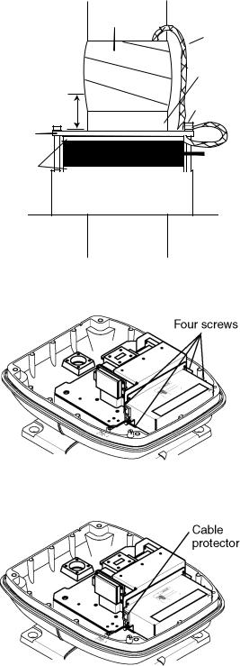
|
Tubing |
|
Shield |
|
Sheath |
Within 4 cm |
Bolt |
|
Plate |
Gasket |
Flat |
washer |
CABLE GLAND
How to fix signal cable in cable gland
6. Unfasten four screws shown in the figure below.
Antenna unit chassis, cover opened
7. Pass the signal cable through the cable protector.
Antenna unit chassis, cover opened
8.Connect the signal cable to the RTB Board (03P9249), referring to the interconnection diagram and the figure below.
9.Attach three EMI cores to the signal cable as shown below.
1-18
Antenna unit chassis, cover opened
10.Fix the signal cable with the cable clamp.
11.Release the stay and close the cover. Loosely fasten the cover fixing screws; you will have to make some adjustments inside after completion of wiring.
Note: When closing the cover, set the gaskets to grooves in the bottom chassis, then tighten bolts.
BOTTOM
CHASSIS
GROOVE
GASKET
SCANNER BOLT
Torque : 9.8 ±0.1 N .m
1-19
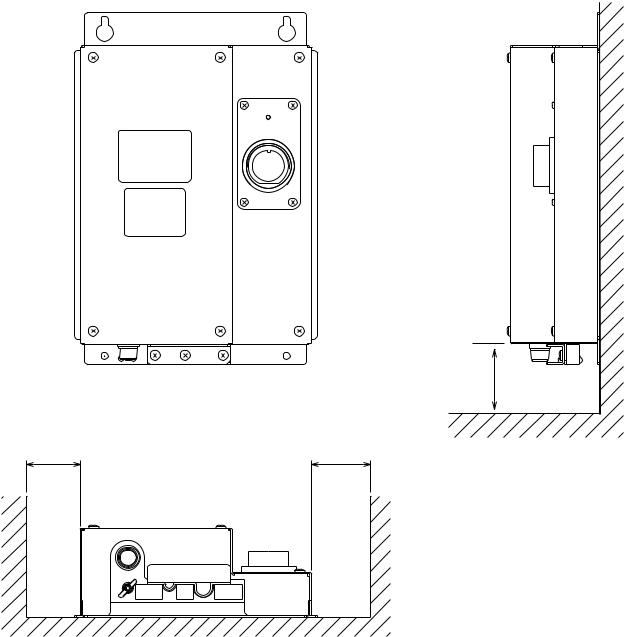
1.4Mounting of Power Supply Unit for MODEL 1953C
MODEL 1953C has its own power supply because of high power consumption.
The power supply unit can be installed almost anywhere provided the location is dry, well-ventilated, sufficient maintenance space is provided (within 5 m from the display unit).
Note: Do not install the power supply unit on the overhead.
Service space: 150
Service |
Service |
space: 100 |
space: 100 |
Power supply unit
1-20
Loading...