


 Loading...

C
9 - 5 2 , A s h i h a r a - c h o , N i s h i n o m i y a , J a p a n
T e l e p h o n e : |
0 7 9 8 - 6 5 - 2 1 1 1 |
T e l e f a x : |
0 7 9 8 - 6 5 - 4 2 0 0 |
A l l r i g h t s r e s e r v e d .  Printed in Japan
P U B . N o . I M E - 5 6 1 4 0 - E
( T E N I ) |
F S - 1 5 0 3 |
|
 Y o u r L o c a l A g e n t / D e a l e r
F I R S T E D I T I O N |
: |
A P R . 1 9 9 8 |
E |
: |
J U L . 4 , 2 0 0 1 |
 SAFETY INSTRUCTIONS
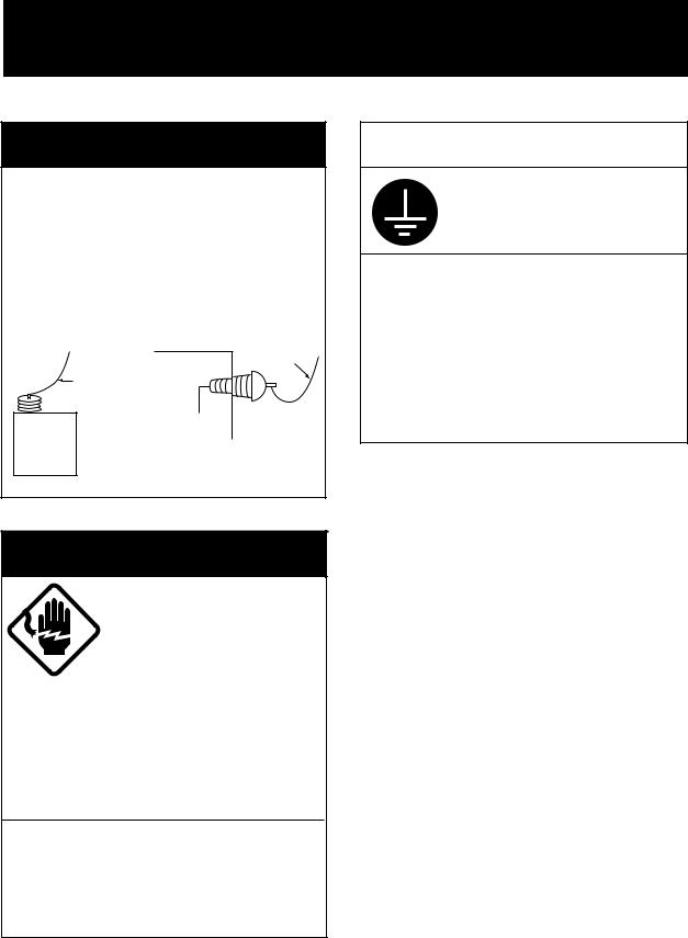
 DANGER
Never touch the SSB antenna, antenna coupler or lead-in insulator when the SSB radiotelephone is transmitting.
High voltage which will cause death or serious injury is present at the locations mentioned above when the SSB radiotelephone is transmitting.
|
Antenna |
|
Indoor |
Wire |
|
Antenna Wire |
|
|
(High Voltage) |
|
|
|
Lead-in |
|
Antenna |
Insulator |
|
(High |
||
Coupler |
||
Voltage) |
||
|
 CAUTION
Ground the equipment to prevent electrical shock and mutual interference.
Observe the following compass safe distances:
Equipment |
Standard |
Steering |
|
compass |
compass |
|
|
|
Transceiver |
1.1 m |
0.8 m |
Ant. Coupler |
0.6 m |
0.5 m |
MIC, Handset |
0.6 m |
0.4 m |
|
|
|
 WARNING
Do not open the cover unless totally familiar with electrical circuits and service manual.
High voltage exists inside the equipment, and a residual charge remains in capacitors several minutes after the power is turned off. Improper handling can result in electrical shock.
Turn off the power at the switchboard before beginning the installation.
Fire or electrical shock can result if the power is left on.
i
TABLE OF CONTENTS
EQUIPMENT LISTS ...................................................................................................... |
iii |
SYSTEM CONFIGURATION ..................................................................................... |
v |
1. MOUNTING
1.1 |
Mounting of Transceiver Unit .................................................................................... |
1-1 |
1.2 |
Mounting of Antenna Coupler.................................................................................... |
1-3 |
1.3 |
Ground System ........................................................................................................... |
1-6 |
1.4 |
Mounting of Antenna ................................................................................................. |
1-7 |
2. WIRING ........................................................................................................................ |
2-1 |
|
3. WIRING OF OPTIONAL EQUIPMENT |
|
|
3.1 |
NBDP Terminal DP-6................................................................................................. |
3-1 |
3.2 |
DSC Terminal DSC-60 ............................................................................................... |
3-1 |
3.3 |
Remote Station RB-500 ............................................................................................. |
3-2 |
3.4 |
Distributor DB-120/DB-500 ...................................................................................... |
3-2 |
3.5 REMOTE and CONTROL Boards ............................................................................. |
3-3 |
|
3.6 |
BK (Break-in) Connection ......................................................................................... |
3-4 |
3.7 Telex Filter ................................................................................................................. |
3-4 |
|
3.8 SW Regulator (SW REG board) ................................................................................ |
3-5 |
|
3.9 Dummy Load ............................................................................................................. |
3-6 |
|
3.10 Floating Ground Radiotelephone (FS-5000, etc.) .................................................... |
3-7 |
|
4. INSTALLATION CHECK |
|
|
4.1 lnstallation Checks ..................................................................................................... |
4-1 |
|
4.2 |
User Channel Registration ......................................................................................... |
4-2 |
PACKING LISTS .......................................................................................................... |
A-1 |
|
OUTLINE DRAWINGS .............................................................................................. |
D-1 |
|
SCHEMATIC DIAGRAMS ....................................................................................... |
S-1 |
|
ii
EQUIPMENT LISTS
Standard Set
Name |
Type |
Code No. |
Qty |
Remarks |
|
|
|
|
|
|
|
Transceiver Unit |
FS-1503 |
— |
1 |
With power cable |
|
|
|
|
|
|
|
|
FS-1503A |
— |
|
For U.S.A |
|
|
|
|
|
|
|
Antenna Coupler |
AT-1503 |
— |
1 |
|
|
|
|
|
|
|
|
Accessories |
FP05-05000 |
000-050-908 |
1 |
With MIC |
|
|
|
|
|
|
|
|
FP05-05010 |
000-050-909 |
1 |
No MIC |
|
|
|
|
|
|
|
Spare Parts |
SP05-04400 |
005-939-850 |
1 |
For transceiver unit |
|
|
|
|
|
|
|
Installation |
CP05-07600 |
000-050-906 |
1 |
With antenna coupler |
|
Materials |
|
|
|
|
|
CP05-07610 |
000-050-907 |
1 |
No antenna coupler |
||
|
|||||
|
|
|
|
|
Note: See packing lists on pages A-1 to A-4 for details.
iii
Optional Equipment
Name |
Type |
Code No. |
Qty |
Remarks |
|
|
|
|
|
AC-DC Power |
PR-270 |
— |
1 |
|
|
|
|
|
|
DC-DC Converter |
PC-220 |
— |
1 |
|
|
|
|
|
|
REMOTE-A Kit |
OP05-82 |
005-939-810 |
1 |
For RS-232C |
|
|
|
|
|
REMOTE-B Kit |
OP05-83 |
005-939-820 |
1 |
For current loop |
|
|
|
|
|
CONTROL Kit |
OP05-41 |
005-920-330 |
1 |
BK connection |
|
|
|
|
|
Bandpass Filter |
SF0L04 |
000-116-693 |
1 |
For NBDP/DSC Terminal |
|
|
|
|
|
SW REG Kit |
OP05-84 |
005-939-830 |
1 |
|
|
|
|
|
|
Dummy Load Assy. |
OP05-85 |
005-939-840 |
1 |
|
|
|
|
|
|
Whip Antenna |
FAW-6D |
000-572-128 |
1 |
|
|
|
|
|
|
Whip Antenna |
FAW6R2 |
000-572-108 |
1 |
|
|
|
|
|
|
Whip Antenna |
FAW-6RP2 |
000-572-109 |
1 |
|
|
|
|
|
|
Whip Antenna |
FAW-6R2A |
000-107-921 |
|
|
|
|
|
|
|
Whip Antenna |
FAW-6RP2A |
000-107-920 |
1 |
|
|
|
|
|
|
Doublet Antenna |
E22 |
000-050-632 |
1 |
|
|
|
|
|
|
Single Wire |
E24 |
000-050-634 |
1 |
|
Antenna |
|
|
|
|
|
|
|
|
|
Double-span |
E25 |
000-050-635 |
1 |
|
Antenna |
|
|
|
|
|
|
|
|
|
Whip Antenna |
E26 |
000-050-636 |
1 |
|
Lead-in Kit |
|
|
|
|
|
|
|
|
|
Whip Antenna |
E27 |
000-050-637 |
1 |
|
Feeder |
|
|
|
|
|
|
|
|
|
Handset |
HS-6000FZ5 |
000-112-623 |
1 |
|
|
|
|
|
|
Noise-cancelling |
M112D |
000-116-487 |
1 |
|
MIC |
4509910 |
|
|
|
|
|
|
|
|
Distributor |
DB-120 |
— |
1 |
|
|
|
|
|
|
Distributor |
DB-500-RS(E) |
— |
1 |
|
|
|
|
|
|
Remote Station |
RB-500 |
— |
1 |
|
|
|
|
|
|
Earth Plate |
04S40801 |
000-572-187 |
1 |
30x1200x0.3 mm |
|
|
|
|
|
Coaxial Cable |
05S0949 |
000-130-485- |
1 |
20, 30, 40, 50 m |
|
|
(6,7,8) |
|
|
|
|
|
|
|
Control Cable |
05S0462 |
000-113-361- |
1 |
20, 30, 40, 50 m |
|
|
(2,3,4) |
|
|
|
|
|
|
|
External |
SEM-21Q |
000-144-917 |
1 |
|
Loudspeaker |
|
|
|
|
|
|
|
|
|
iv
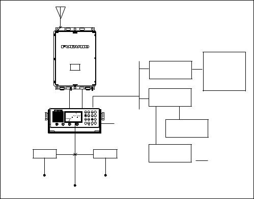
SYSTEM CONFIGURATION
FS-1503 SYSTEM CONFIGURATION
Antenna Coupler
AT-1503
Transceiver Unit
FS-1503
MIC 


 (Handset optionally available)
PC-220
24 VDC
SSB TRANSCEIVER FS-1503 |
|
* |
|
|
|
TX |
|
R |
|
RX |
|
AGC NB |
|
CH |
|
|
H3E |
|
External |
MIC VOLUME RF GAIN |
FREQ/CH |
2182 ALM ENT |
|
OFF |
|
|
|
|
|
|
Speaker |
13.6 V |
13.6 V PR-270 |
|
|
100/110/200/220 VAC
13.6 VDC
|
DSC Terminal |
|
Distributor |
DSC-5/6 |
|
NBDP Terminal |
||
DB-500 |
DP-5/6 |
|
OR |
Remote Station |
|
RB-500 |
||
|
||
Distributor |
|
|
DB-120 |
|
DSC Terminal
DSC-60
NBDP Terminal
DP-6
Option
*Optional pcb (REMOTE A or REMOTE B) required.
FS-1503 system configuration
v
1.MOUNTING
1.1Mounting of Transceiver Unit
General mounting considerations
The transceiver unit can be mounted on the overhead, a bulkhead, on a tabletop, or in a console (flush mounting).
When selecting a mounting location keep the following points in mind:
•Make sure the location is strong enough to support the unit under the conditions of continued vibration and shock normally encountered on the boat. Where necessary, reinforce the mounting location by lining block or doubling plate.
•Locate the unit where it is easily accessible and does not interfere with personnel or operation of other equipment; for example, ship’s wheel.
•Leave enough space around the sides and rear of the unit so a service technician can access the connectors for maintenance.
•Observe the compass safe distance listed in the Safety Instructions to prevent deviation of a magnetic compass.
•If the equipment is to be installed without the hanger, leave sufficient space underneath the the equipment to allow for circulation of cooling air.
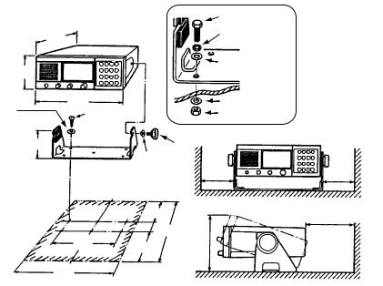
Mounting on overhead, bulkhead or tabletop
1.Using the hanger as a template, mark hole locations.
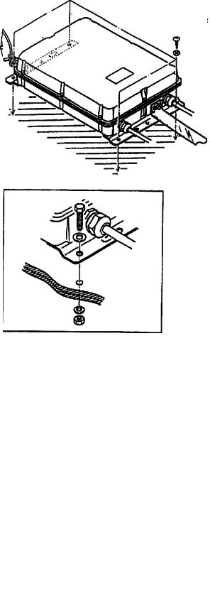
2.Fix the hanger with four sets of self-tapping screws and washers (supplied). (If extra support is required, drill six pilot holes and use bolts, nuts and flat and slotted washers instead of the tapping screws.)
3.Screw washers and knobs into the unit. Set the unit to the hanger and tighten the knobs.
|
|
|
M5 bolt |
|
306 |
|
Slotted washer |
|
|
|
|
112 |
|
Flat washer |
|
|
|
||
Flat |
265 |
|
Flat washer |
Tapping |
|
M5 nut |
|
washer |
screw |
|
|
|
115 |
|
Knob |
|
|
Washer |
|
|
|
|
100 |
|
|
150 |
|
|
|
90 |
|
|
190 |
126 |
155 |
|
|
|
|
|
303 |
|
|
For added support, use nuts, bolts and washers instead of tapping screws.
100
150
Figure 1-1 How to install the transceiver unit in the hanger
1-1
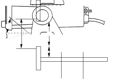
Console mounting
Mounting considerations
In addition to the general mounting considerations mentioned on the previous page, keep the following points in mind when selecting a mounting location:
•Select a place where the LCD can be easily viewed, keeping in mind the LCD viewing angle is as shown in Figure 1-2.
•Leave sufficient space around the unit to permit dispersal of heat after a long transmission.
How to mount the transceiver unit in a console
This method does not require any additional kit. However, the dimensions of the cutout must be accurate since the hanger also is installed. Prepare a cutout in the mounting location whose dimensions are as shown in Figure 1-2.
LCD Viewing 40°
Angle
99
10°
112
37.5
 103
103 
 90
90 
Figure 1-2 Mounting dimensions for console mounting
1-2
1.2 Mounting of Antenna Coupler
The antenna coupler is installed between the antenna and the transceiver, and tunes the antenna to the transmitter.
Mounting considerations
The splashproof construction of the antenna coupler permits installation indoors or outdoors. When selecting a location, keep in mind the following points:
•All wires from the coupler to the antenna radiate radio energy. Keep wires as short as possible and routed away from any grounded conductors such as lifelines, mast shrouds, or fittings.
•For optimum radio energy, locate the coupler close to the antenna base and as near to the ground as possible.
•For outdoor installation, be sure to select a place where the coupler will not take a continual soaking. If necessary, cover the top and sides with a wooden housing or by sealing any opening in the top or sides with silicone sealant.
•For indoor installation, locate the coupler away from GPS and SATNAV receivers and radio equipment to avoid mutual interference. The lead-in wire should be as near to the coupler as possible.
•Select a place where the coupler can be easily maintained, but where it will not interfere with crew or passengers.
•Leave sufficient space around the sides of the coupler for maintenance and checking.
•Observe the compass safe distance listed in the Safety Instructions to prevent deviation of a magnetic compass.
1-3
Mounting the antenna coupler
Mounting methods
The antenna coupler can be fixed to the floor, bulkhead, or on the overhead. For mounting on the bulkhead, floor or overhead, fix the coupler with either tapping screws or M6 nuts, bolts and washers.
INDOOR USE ONLY
Figure 1-3 Typical antenna coupler installations
1-4
How to mount the antenna coupler
For thin bulkhead, use nuts, bolts and and washers instead of tapping screws.
Lead-in insulator
ANTENNA SELECTOR
 Wire clip
From antenna selector
Stand-off insulator
INDOOR INSTALLATION
Figure 1-4 How to mount the antenna coupler
1-5
1.3 Ground System
A good antenna can work well only when it is connected to an efficient rf ground. Without a good ground system, the full potential of this radio cannot be realized.
 CAUTION
Ground the equipment to prevent electrical shock and mutual interference.
Ground for metallic hull
Run a copper strap (option or local supply) between the earth terminal on the antenna coupler and the ship’s superstructure. The length of the copper strap should be as short as possible. (If the coupler is mounted on a metallic mast you can ground the copper strap to the mast; weld a stainless steel bolt to the mast and connect the copper strap there.)
Copper strap
Braze
Ground plate
(piece of steel plate)
Solder
Weld to ship's superstructure.
For outdoor installation, paint to prevent rust.
Figure 1-5 Ground for a metallic hull
Ground for non-metallic hull
Run a copper strap (option or local supply) between the ground terminal of the antenna coupler and the radio ground system. The length of the copper strap should be as short as possible.
Grounding the transceiver unit
Run the ground wire (supplied) between the transceiver unit and ship’s ground, to prevent interference and protect the equipment against lightning.
1-6
1.4 Mounting of Antenna
About antennas
The antenna plays the most important role in radio communication. If it cannot receive or transmit effectively because of improper installation, even the most sophisticated transceiver will be rendered useless.
There are various types of SSB antennas. The most commonly used are a long wire and a whip. Whatever antenna is to be used, the antenna coupler can tune a long wire or whip whose total length is 6 to 15 meters. Although a longer antenna is preferable when the radio is operated only on low frequencies, use this size of antenna to ensure stable automatic tuning on all bands.
A long wire antenna is inexpensive and in general provides better performance than a whip antenna, provided the vertical part is long enough.
A whip antenna is easier than a long wire antenna to install and provides good overall coverage of most SSB frequencies. In fact, if you don’t plan to venture more than 500 miles from shore and the ground system is excellent, a simple 7 m (23 feet) whip antenna will probably suffice. A whip is installed as high as possible (though height is not so critical as with VHF since SSB is frequency dependent, not range dependent), away from any nearby objects.
Mounting considerations
When selecting a mounting location, keep the following points in mind:
•The length of the vertical portion should be longer than 4 meters, and the slant angle of that part should be within 10 degrees of vertical.
•Separate the antenna as far away as possible from stays, metallic objects, direction finder antenna, Inmarsat antenna.
•Locate the insulator away from funnels and masts.
•If the antenna coupler is installed outdoors, use a lead-in insulator to make the connection. If necessary, use a high quality antenna switch and stand-off insulator.
•If the antenna is connected directly to the coupler, use a strain insulator to prevent insulator fatigue.
1-7

Typical antenna installations
|
Long wire antenna |
Whip antenna |
|
Ship station |
Power boats |
||
On ship stations, the long wire antenna is spanned |
On power boats, selection of a mounting location |
||
between supporting structures. The length of the |
for a whip antenna is much easier, since there is |
||
horizontal wire should be between 6 and 15 |
no mast or deck fixture to worry about. A whip |
||
meters. And the length of the vertical wire should |
antenna can be installed almost anywhere, |
||
be no less than 5 meters, the longer the better |
again the higher the better. If your boat has a |
||
transmission. |
flybridge, install it there. If not, install it atop the |
||
|
|
|
cabin. Make sure the mounting location is |
|
|
|
sufficiently apart from any nearby objects |
|
|
|
which might affect communication. |
|
|
|
|
Sailboat
On sailboats, the long wire antenna is mounted on the backstay using special high-voltage insulators. Make sure the selected location is sufficiently apart from any metal riggings which might cause detuning. If a wire topping lift is used with an insulated backstay, special care must be taken to ensure the topping lift does not get caught in the backstay since the antenna may be shorted to ground— damaging the transmitter.
Fishing boat/Sailboat
For whip antenna installation on a fishing boat or sailboat, the mounting location must be chosen carefully so as not to interfere with vessel operation. In case of a sailboat, locate the antenna away from the spinnaker, jib and of course the boom. Stay especially clear of the backstay. The taffrail is a good location in the event of dismasting, since the antenna won’t
be carried away. The best location, however, is atop the mast, the higher the better for effective communication. It is always a good idea to keep spare wire or an emergency antenna onboard in case of an emergency.
Figure 1-6 Typical antenna installations
1-8
Loading...