


FR-7112
Table of contents
 Loading...
MARINE RADAR
MODEL
FR-7062/7112/7252
Back

The paper used in this manual
is elemental chlorine free.
FURUNO Authorized Distr ibutor/DealerFURUNO Authorized Distr ibutor/Dealer
9-52
A
shihara-cho,9-52
A
shihara-cho,
Nishinomi
y
a 662-8580, JAPANNishinomi
y
a 662-8580, JAPAN
Tele
p
hone :Tele
p
hone : 0798-65-21110798-65-2111
FaxFax 0798-65-42000798-65-4200
::
FIRST EDITION :FIRST EDITION :APR.APR. 19981998
Printed in JapanPrinted in Japan
A
ll ri
g
hts reserved.
A
ll ri
g
hts reserved.
H1H1 :: JAN.JAN. 19, 200619, 2006
Pub. No.Pub. No. OME-34590OME-34590
*
0
0080819803*
*
0
0080819803*
*
0
0080819803*
*
0
0080819803*
(( YOSHYOSH ))
FR-7062/7112/7252FR-7062/7112/7252
* 0 0 0 8 0 8 1 9 8 0 3 ** 0 0 0 8 0 8 1 9 8 0 3 *
*
O
ME
3
4590H10*
*
O
ME
3
4590H10*
*
O
ME
3
4590H10*
*
O
ME
3
4590H10*
* O M E 3 4 5 9 0 H 1 0 ** O M E 3 4 5 9 0 H 1 0 *
i
DANGERDANGER
SAFETY INSTRUCTIONS
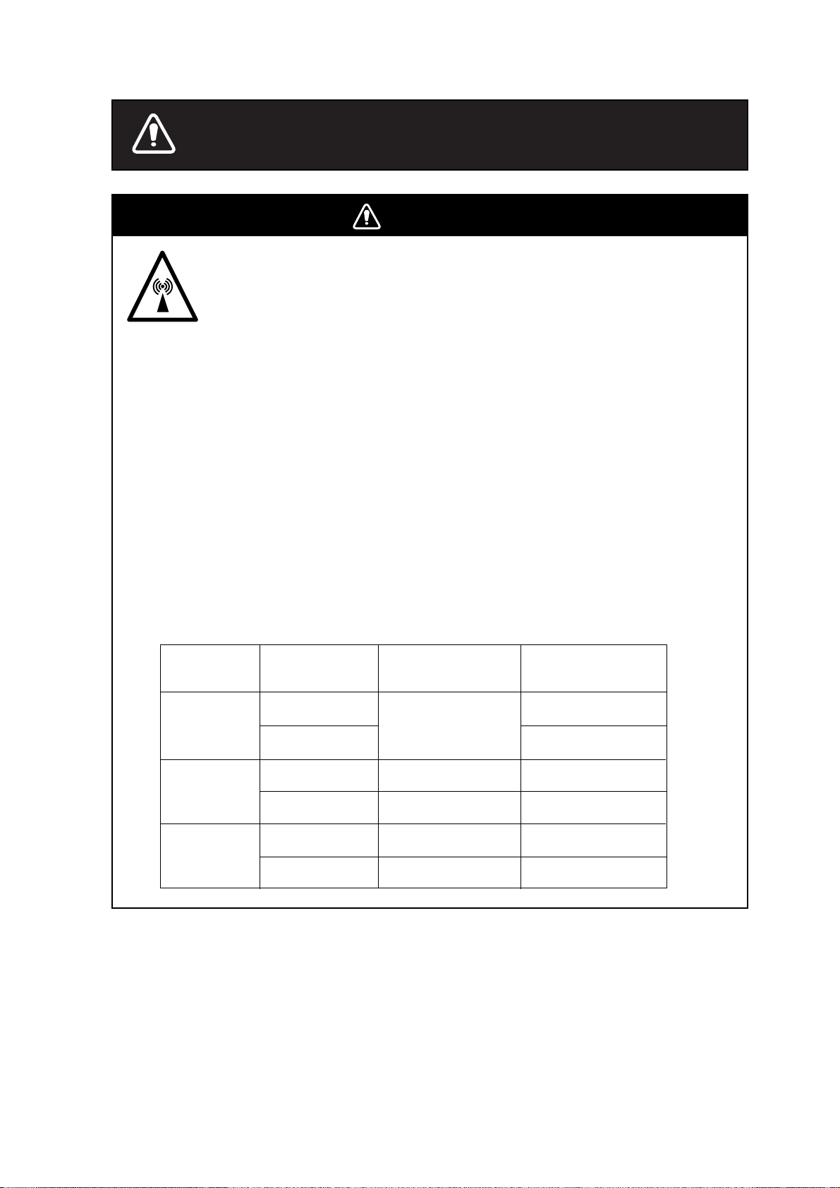
Radio Frequency Radiation Hazard
The radar antenna emits electromagnetic radio frequency (RF) energy which can be
harmful, particularly to your eyes. Never look directly into the antenna aperture from a
close distance while the radar is in operation or expose yourself to the transmitting
antenna at a close distance.
Distances at which RF radiation levels of 100 and 10 W/m exist are given in the table
below.
Note: If the antenna unit is installed at a close distance in front of the wheel house,
your administration may require halt of transmission within a certain sector of antenna
revolution. This is possible - Ask your FURUNO representative or dealer to provide
this feature.
2
Model
Radiator type
Distance to 10 W/m
point
2
Distance to 100 W/m
point
2
FR7062
(X-bnd, 6 kW)
1.2 m
0.2 m
XN12A (4')
Stay away from transmitting antenna.
The radar antenna emits microwave radiation which can be harmful to the
human body, particularly the eyes. Never look directly into the antenna
radiator from a distance of less than 1 m when the radar is in operation.
XN13A (6')
Nil
FR7112
(X-bnd, 12 kW)
XN12A (4')
XN13A (6')
1.1 m
2.0 m
1.4 m
0.5 m
FR7252
(X-bnd, 25 kW)
XN12A (4')
XN13A (6')
0.4 m
5.4 m
3.6 m
Nil
ii
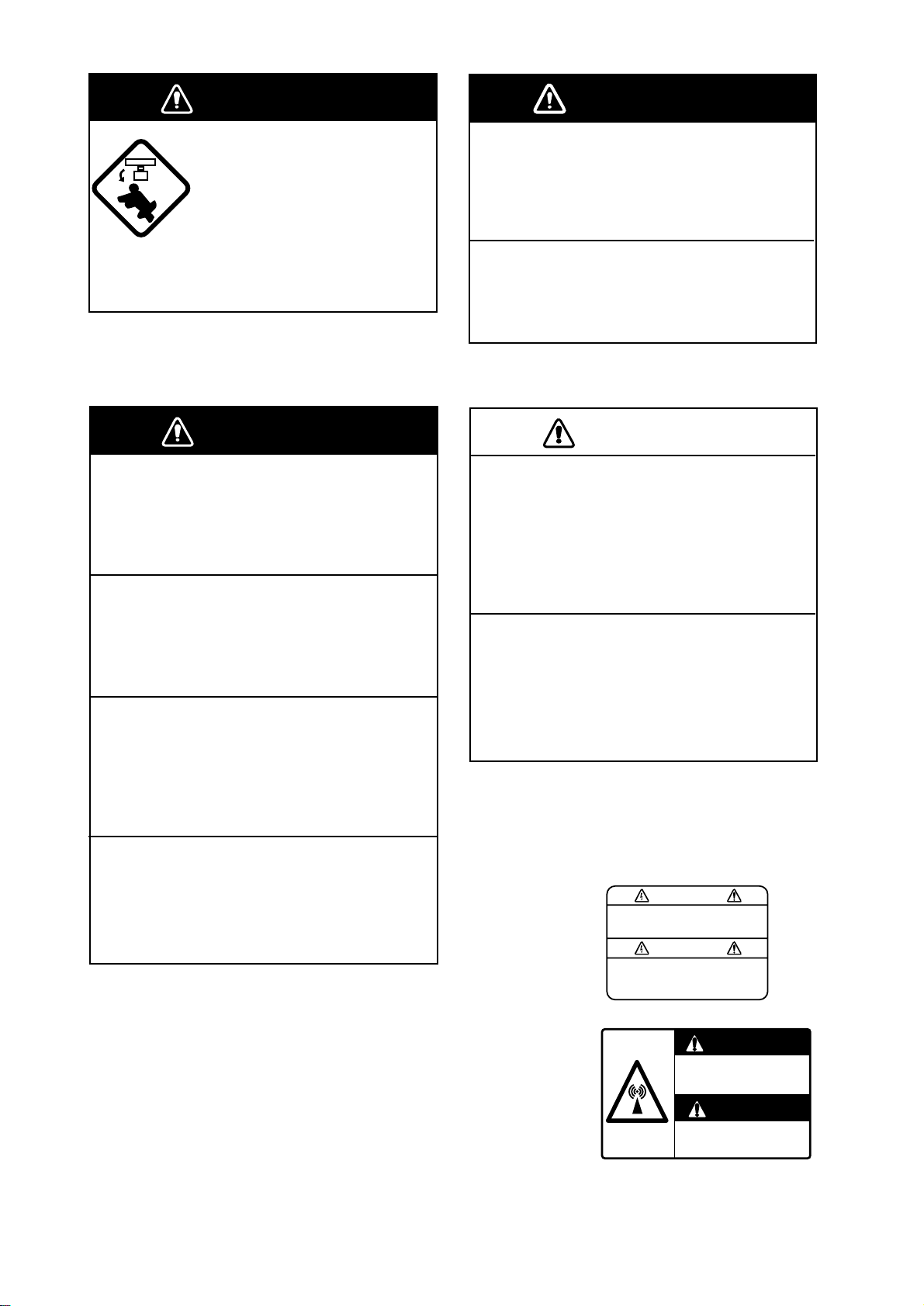
DANGER
Before turning on the radar
make sure no one is near the
scanner unit.
Prevent the potential risk of
someone begin struck by the
rotating antenna and exposure
to RF radiation hazard.
CAUTION
No one navigation device should ever be
solely replied upon for the navigation of
a vessel.
Always confirm position against all available
aids to navigation, for safety of vessel and
crew.
The guard alarm is a useful anti-collision
aid, but does not relieve the operator of the
responsibility to also keep a visual lookout
for possible collision situations. The alarm
should never be used as the sole means for
detecting possible collision situations.
WARNING
Do not open the equipment.
Improper handling can result in electrical
shock. Only qualified personnel shold
work inside the equipment.
Do not disassemble or modify the
equipment.
Fire electrical shock or serious injury can
result.
Turn off the power immediately if water
leaks into the equipment or the equip-
ment is emitting smoke or fire.
Continued use of the equipment can
cause fire or electrical shock.
Do not place liquid-filled containers on
the top of the equipment.
Fire or electrical shock can result if a liquid
spills into the equipment.
WARNING
Use the proper fuse.
Fuse rating is shown in the chapter 5.
Use of a wrong fuse can result in equipment
damage
Do not operate the equipment with wet
hands.
Electrical shock can result.
Two warning labels are attached to the display
unit and scanner unit. Do not remove these label.
If labels are peeling off or are illegible, contact a
FURUNO agent or dealer.
WARNING
To avoid electrical shock, do not
remove cover. No user-serviceable
parts inside.
WARNING
Radiation hazard. Only qualified
personnel should work inside scanner.
Confirm that TX has stopped before
opening scanner.
<Display Unit>
Name: Warning Label (1)
Type: 86-003-1011-1
Code no.: 100-236-231
<Scanner Unit>
Name: Radiation Warning
Label
Type: 03-142-3201-0
Code no.: 100-266-890

iii
COMPLIANCE WITH R&TTE DIRECTIVE 1999/5/EC
This radar c omplies with the R&TTE Direc tive 1999/5/EC. In accordance w ith Article 6-3 of
this di r ec ti ve, FURUNO intends to put this radar on the market of the f ollowing countr ies in
EU as well other markets.
Austria, Belgium, Cy prus , Denmark, Estonia, Finland, F r anc e, Germany, Greece, Hungary,
Ireland, Italy, Latvia, Lithuania, Malta, Poland, Portugal, Slovenia, Spain, Sweden, The
Netherlan ds , United Kingdom, Iceland, Nor way
iii
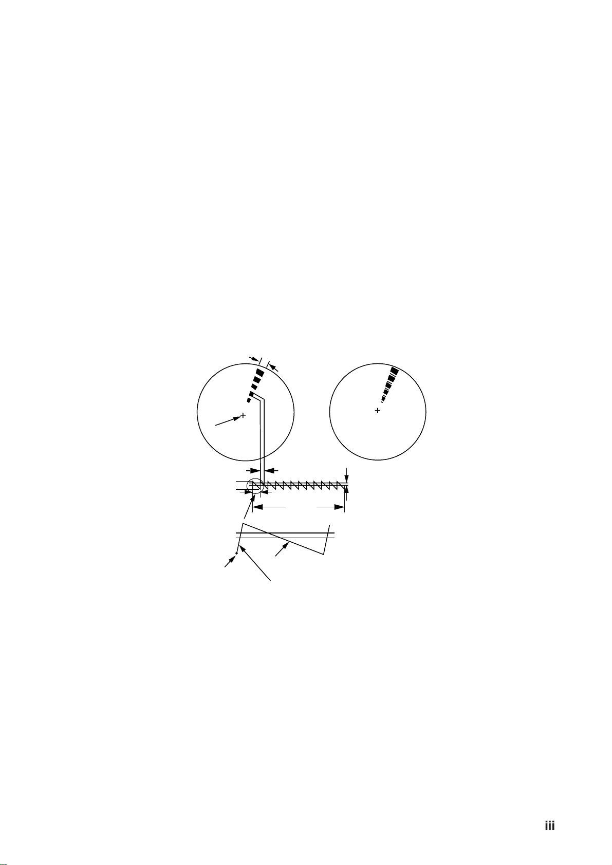
SART (Search and Rescue Transponder)
A Search and Rescue Transponder (SART) may be triggered by any X-Band (3 cm) radar
within a range of approximately 8 n.miles. Each radar pulse received causes it to transmit
a response which is swept repetitively across the complete radar frequency band. When
interrogated, it first sweeps rapidly (0.4 µsec) through the band before beginning a rela-
tively slow sweep (7.5 µsec) through the band back to the starting frequency . This process
is repeated for a total of twelve complete cycles. At some point in each sweep, the SART
frequency will match that of the interrogating radar and be within the pass band of the
radar receiver . If the SART is within range, the frequency match during each of the 12 slow
sweeps will produce a response on the radar display , thus a line of 12 dots equally spaced
by about 0.64 nautical miles will be shown.
When the radar to the SART is reduced to about 1 n.miles, the radar display may show
also the 12 respopnses generated during the fast sweeps. These additional dot responses,
which also are equaly spaced by 0.64 nautical miles, will be interspersed with the original
line of 12 dots. They will appear slightly weaker and smaler than the original dots.
Radar antenna
beamwidth
Screen A: When SART
is distant
SART mark
length
Position
of SART
Radar receiver
bandwidth
Sweep time
9500 MHz
9200 MHz
7.5 µs
95 µs
Sweep
starting
Low frequency sweep signal
Fast sweep signal
Screen B: When SART
is close
Showing SART marks on the radar display
To show the SART marks only on the radar display, detune the radar receiver by the
manual tuning out of best tuning condition. This erases or weakens all normal radar ech-
oes, but, the SART marks are not erased because the SAR T response signal scans over
all frequencies in the 9 GHz band. When the radar approaches the SART in operation, the
SART marks will enlarge to large arcs, blurring a large part of the screen. Reduce the
sensitivity and adjust the sea clutter control of the radar.
iv

iv
Summary to detect SART response
1. Use range scale of 6 or 12 nm as the spacing between the SART responses is about
0.6 nm (1125 m) to distinguish the SART.
2. Turn off the A/C AUTO function.
3. Turn off the Interference Rejector.
General remarks on receiving SART
Radar range scale
When looking for a SART it is preferable to use either the 6 or 12 nautical mile range scale.
This is because the total displayed length of the SART response of 12 (or 24) dots may
extend approximately 9.5 nautical miles beyond the position of the SART and it is neces-
sary to see a number of response dots to distinguish the SART from other responses.
SART range errors
When responses from only the 12 low frequency sweeps are visible (when the SART is at
a range greater than about 1 n.mile), the position at which the first dot is displayed may be
as mush as 0.64 n.mile beyond the true position of the SART. When the range closes so
that the fast sweep responses are seen also, the first of these will be no more than 150
meters beyond the true position.
v

v
Congratulations on your choice of the
FURUNO FR-7062/7112/7252 Marine Radar.
We are confident you will see why the
FURUNO name has become synonymous with
quality and reliability.
For over 40 years FURUNO Electric Company
has enjoyed an enviable reputation for innova-
tive and dependable marine electronics equip-
ment. This dedication to excellence is furthered
by our extensive global network of agents and
dealers.
Y our radar is designed and constructed to meet
the rigorous demands of the marine environ-
ment. However, no machine can perform its
intended function unless properly operated and
maintained. Please carefully read and follow
the recommended procedures for operation and
maintenance.
W e would appreciate hearing from you, the end-
user, about whether we are achieving our pur-
poses.
Thank you for considering and purchasing
FURUNO equipment.
Note: In this manual, "N-type" means Nether-
lands specification radar.
Features
Your radar has a large variety of functions, all
contained in a remarkably small cabinet.
The main features of the model FR-7062 are
¡ Traditional FURUNO reliability and qual-
ity in a compact, lightweight and low-cost
radar.
¡ Durable brushless antenna motor.
¡ On-screen alphanumeric readout of all op-
erational information.
¡ Standard features include EBL (Electronic
Bearing Line), VRM (Variable Range
Marker), Guard Alarm, Display Off Center,
and Echo Trail.
¡ W atchman feature periodically transmits the
radar to check for radar targets which may
have entered the alarm zone.
¡ Ship’ s position in latitude and longitude and
Loran C TDs, range and bearing to a
waypoint, speed, heading, and course can be
shown in the bottom text area. (Requires a
navigation aid which can output such data
in IEC 1162 format.)
¡ Zoom feature provided.
¡ Auto Plotter ARP-10 (option) acquires and
tracks up to 10 targets, and is installed in the
display unit.
¡ Cursor position data (TLL) can be output to
a plotter (option).
FOREWORD
vi

vi
TABLE OF CONTENTS
FOREWORD............................... v
MENU TREE ............................. vii
SYSTEM CONFIGURATION.... viii
1. PRINCIPLE OF OPERATION
1.1 What is Radar?.................................1-1
1.2 How Ships Determined Position
Before Radar ...................................1-1
1.3 How Radar Determines Range ........1-1
1.4 How Radar Determines Bearing ......1-1
1.5 Radar Wave Speed and Antenna
Rotation Speed ................................1-1
1.6 The Radar Display ...........................1-1
2. BASIC OPERATION
2.1 Control Description .........................2-1
2.2 Display Indications and Markers .....2-2
2.3 Turning the Radar On/Off................2-3
2.4 Transmitting.....................................2-3
2.5 Stand-by...........................................2-3
2.6 Selecting the Range .........................2-4
2.7 Adjusting Picture Brilliance.............2-4
2.8 Adjusting Receiver Sensitivity ........2-4
2.9 Adjusting the A/C SEA Control
(reducing sea clutter).......................2-4
2.10 Adjusting the A/C RAIN Control
(reducing rain clutter)......................2-5
2.11 Selecting the Presentation Mode....2-6
2.12 Erasing the Heading Marker,
North Marker..................................2-6
2.13 Magnifying Long Range Echoes
(echo stretch) ...................................2-6
2.14 Measuring the Range .....................2-7
2.15 Measuring the Bearing...................2-7
2.16 Using the Offset EBL ....................2-8
2.17 Shifting (off centering) the Picture 2-9
2.18 Zoom..............................................2-9
3. ADVANCED OPERA TION
3.1 Basic Menu Operation .....................3-1
3.2 Index Lines ......................................3-1
3.3 Suppressing Radar Interference .......3-2
3.4 Selecting Pulsewidth........................3-2
3.5 Displaying Navigation Data ............3-3
3.6 Echo Trail.........................................3-4
3.7 Guard Alarm ....................................3-4
3.8 Watchman ........................................3-6
3.9 OTHER MENU Description............3-7
3.10 Function Keys................................3-8
3.11 Adjusting Brilliance of Markers ....3-8
3.12 Suppressing Second-Trace Echoes 3-8
3.13 Suppressing Noise .........................3-8
3.14 Outputting Target Position.............3-8
3.15 Tuning the Receiver.......................3-8
4. FALSE ECHOES
4.1 Multiple Echoes ...............................4-1
4.2 Side-lobe Echoes .............................4-1
4.3 Indirect Echoes ................................4-2
4.4 Blind and Shadow Sectors ...............4-2
5. MAINTENANCE & TROUBLE-
SHOOTING
5.1 Preventive Maintenance...................5-1
5.2 Replacing the Fuse...........................5-1
5.3 Troubleshooting...............................5-2
5.4 Self Test ...........................................5-3
5.5 Life Expectancy of Magnetron ........5-3
6. ARP-10 (OPTION)
6.1 General.............................................6-2
6.2 Keys Used for Auto Plotter..............6-2
6.3 Activating the Auto Plotter ..............6-3
6.4 Manual Acquisition..........................6-4
6.5 Automatic Acquisition .....................6-4
6.6 Terminating Tracking of Targets......6-5
6.7 Displaying Target Data ....................6-5
6.8 Mode and Length of Vectors............6-6
SPECIFICATIONS ................ SP-1
INDEX .....................................IN-1
Declaration of Conformity
vii
vi
viii
.. ix
vii
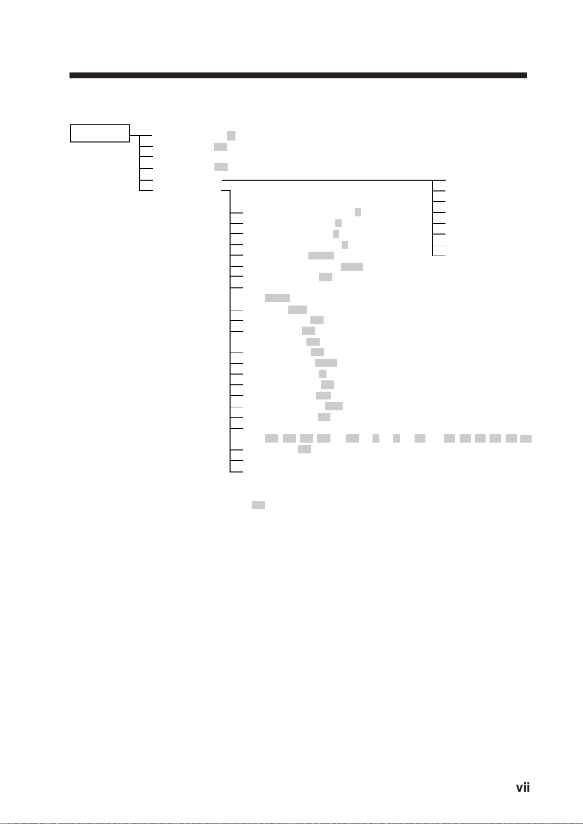
MENU TREE
RINGS (Off, 1, 2, 3, max)
INDEX LINE (Off, On)
DISP DATA (NAV, Auto plotter, NAV and Auto plotter)
INT REJECT (Off, On)
ARP-10 MENU
OTHER MENU
1.
2.
3.
4.
5.
6.
7.
8.
9.
10.
11.
12.
13.
14.
15.
16.
17.
18.
19.
20.
21.
22.
23.
Panel Dimmer (1, 2, 3, 4)
Mark Brill (1, 2, 3, 4)
HD Mark (1, 2, 3, 4)
Characters (1, 2, 3, 4)
Trail Tone (Single, Multi)
Pulselength (Short, Long)
Noise Reject (Off, On)
Trail Time
(15sec, 30sec, 1min, 3min, 6min, 15min, 30min, Cont)
Tune (Auto, Manual)
WPT Mark (Off, On)
EBL Ref (Rel, True)
VRM Unit (nm, km, sm)†
Watchman (Off, 5min, 10min, 20min)
STBY Disp (Norm, Econo, Nav)
Guard Mode (In, Out)
Own Position (L/L, TD)
Cursor Posi (B/R, L/L)
Alm Sense LV (Low, Mid, High)
Dead Sector (Off, On)
Range
(1/8, 1/4, 1/2, 3/4, 1, 1.5, 2, 3, 4, 6, 8, 12, 16, 24, 36, 48, 64, 72, 96)*
2nd Rej (Off, On)
Self Test
Installation Setup
1. Display
2. All Cancel
3. Vector Ref
4. Vector Length
5. History
6. CPA SET
7. TCPA SET
8. AUTO ACQ
MENU KEY
(With ARP-10 only.)
= Default setting
*Maximum range
FR-7062: 64
FR-7112: 72
FR-7252: 96
†: Not available on N-type radar.
viii

viii
SYSTEM CONFIGURATION
*Equivalent to NMEA 0183
Option
FR-7062/7112: RDP-122
FR-7252: RDP-123
Auto Plotter
ARP-10
Navigation
device
IEC 1162* (In/Out)
IEC 1162* (In/Out)
Video Sounder
Gyro
compass
Gyro Converter
AD-100
Integrated Heading
Sensor PG-1000
FR-7062/7112: 12/24/32 VDC
FR-7252: 24/32 VDC
Rectifier
RU-3423,
RU-1746B-2
115/230 VAC
1ø, 50/60 Hz
External Alarm
Buzzer OP03-21
Slave Display
FMD-811/8010
Radar Plotter
RP-110
Scanner Unit
FR-7112
XN12A-RSB-0072-060
XN13A-RSB-0072-060
XN12A-RSB-0073-060
FR-7062
XN12A-RSB-0070-059
XN13A-RSB-0070-059
XN12A-RSB-0073-059
FR-7252
XN12A-RSB-0072-061
XN13A-RSB-0072-061
XN12A-RSB-0073-061
†
†RU-1746B-2 is available for FR-7252
using XN12A (48 rpm) and XN13A.
Display Unit
CVD Converter
RP-6065B
Remote Display
FMD-1800
#
# Available with 24 rpm antenna only.
ix

x
This p age is intentionally left bl ank .

1-1
1.1 What is Radar?
The term “RADAR” is an acronym meaning
RAdio Detection And Ranging. Although the
basic principles of radar were developed dur-
ing World War II, echoes as an aid to naviga-
tion is not a new development.
1.2 How Ships Determined
Position Before Radar
Before the invention of radar , when running in
fog near a rugged shoreline, ships would sound
a short blast on their whistles, fire a shot, or
strike a bell. The time between the origination
of the sound and the returning of the echo indi-
cated how far the ship was from the cliffs or the
shore. The direction from which the echo was
heard indicated the relative bearing of the shore.
1.3 How Radar Determines Range
Radar determines the distance to the target by
calculating the time difference between the
transmission of a radar signal and the reception
of the reflected echo. It is a known fact that ra-
dar waves travel at a nearly constant speed of
162,000 nautical miles per second. Therefore
the time required for a transmitted signal to
travel to the target and return as an echo to the
source is a measure of the distance to the tar-
get. Note that the echo makes a complete round
trip, but only half the time of travel is needed to
determine the one-way distance to the target.
This radar automatically takes this into account
in making the range calculation.
1. PRINCIPLE OF OPERATION
1.4 How Radar Determines
Bearing
The bearing to a target found by the radar is
determined by the direction in which the radar
scanner antenna is pointing when it emits an
electronic pulse and then receives a returning
echo. Each time the scanner rotates pulses are
transmitted in the full 360 degree circle, each
pulse at a slightly different bearing from the
previous one. Therefore, if one knows the di-
rection in which the signal is sent out, one knows
the direction from which the echo must return.
1.5 Radar Wave Speed and
Antenna Rotation Speed
Note that the speed of the radar waves out to
the target and back again as echoes is extremely
fast compared to the speed of rotation of the
antenna. By the time radar echoes have returned
to the scanner, the amount of scanner rotation
after initial transmission of the radar pulse is
extremely small.
1.6 The Radar Display
The range and bearing of a target are displayed
on what is called a Plan Position Indicator (PPI).
This display is essentially a polar diagram, with
the transmitting ship’s position at the center.
Images of target echoes are received and dis-
played at their relative bearings, and at their
distance from the PPI center.
With a continuous display of the images of tar -
gets, the motion of the transmitting ship is also
displayed.
1-2
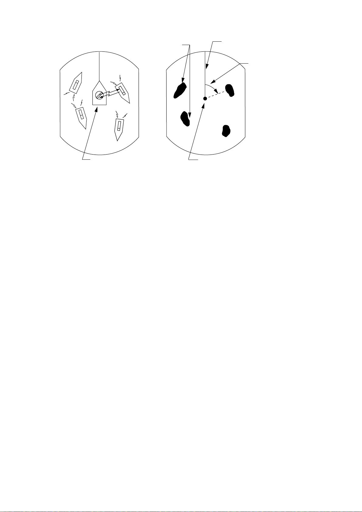
A
B
C
D
Own ship
(radar)
D
A
B
C
Heading marker
Targets
Own ship
in center
(A) Bird's eye view of situation
(B) Radar picture of (A)
Range and bearing
of a target, relative
to own ship, are
readable on the PPI.
Figure 1-1 How radar works
2-1
2. BASIC OPERATION
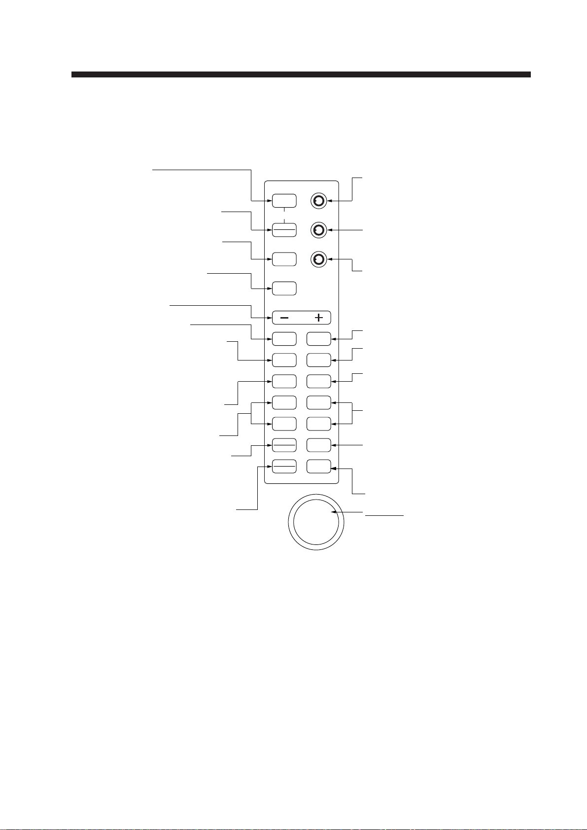
2.1 Control Description
POWER
F 1
F 2
BRILL
SHIFT
ZOOM
ECHO
TRAIL
MODE
GUARD
ALARM
EBL
OFFSET
SELECT
CANCEL
ACQ
ENTER
EBL 1 VRM 1
VRM 2
TLL
MENU
EBL 2
RANGE
OFF
ECONOMY
STBY
T X
GAIN
HM OFF(PUSH)
A/C SEA
A/C AUTO(PUSH)
ES(PUSH)
A/C RAIN
Turns power on.
Press together with [STBY/TX] key
to turn power off.
Alternates between stand-by and
transmit.
NAV data and ARPA data can be
displayed individually or together.*
Suppresses electrical noise.*
Selects radar range.
Adjusts display brilliance.
(Long press) Doubles size of area
between your vessel and location
selected by cursor.
(Short press) Shifts your vessel's
position to cursor location.
(Control) Adjusts sensitivity of radar
receiver.
(Switch) Temporarily erases heading
marker (and north marker if displayed).
(Control) Reduces sea clutter.
(Switch) Automatically reduces sea
and rain clutters.
(Control) Reduces rain clutters.
(Switch) Enlarges echoes.
Selects presentation mode among
HU, CU, NU, and TM.
Sets/cancels guard alarm; silences
audible alarm.
Measures range and bearing
between two targets; predicts
collision course.
Turns corresponding VRM on/off.
Opens/closes menus.
Trackball
(1) Shifts cursor, EBL and VRM.
(2) Sets guard zone.
(3) Selects items and options on
menu.
(4) Shifts origin of EBL and VRM.
Displays target movement in
afterglow.
Turns corresponding EBL on/off.
(Long press) Terminates plotting of
the target selected with cursor.†
(Short press) Displays the data of
target selected with the cursor.†
(1) Acquires the target selected with
the cursor.†
(2) Registers selection on menus.
* Default switch function.
† Requires ARP-10 (option).
(Long press) Outputs target data position
data to plotter.
(Short press) Alternately displays cursor
position display in lat/long or bearing/range.
(Functuion is available when nav data
is not displayed.)
Figure 2-1 Control panel
2-2
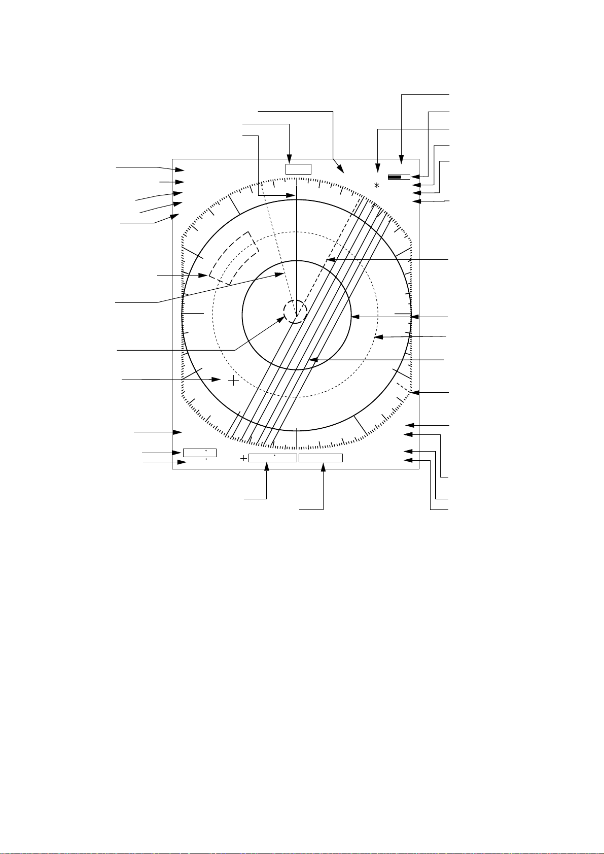
2.2 Display Indications and Markers
HDG 234.5°
SP
HU RM
0. 125NM
0. 0625
TRAIL
30min
ZOOM
ES1
AUTO
25 : 38
G (OUT)
IR2
VRM
0.048NM
0.100NM
13.5 R
0.142NM
A/C
AUTO
EBL/PI
345.6 R
23.0 R
NR
2ND
ECHO
Tuning status (P.3-8
)
Echo trail time (P.3-
4)
Guard Zone (P.3-4)
Zoom (P.2-9) or
Off center (P.2-9)
Echo Stretch (P.2-6
)
EBL2 (P.2-7)
Range ring (P.2-7)
VRM2 (P.2-7)
North marker (P.2-6
)
Interference rejector
(P.3-2)
VRM2 range (P.2-7
)
VRM1 range (P.2-7
)
Cursor range (P.2-7)
Cursor bearing (P.2-8)
EBL2 bearing (P.2-8)
EBL1 bearing (P.2-8)
A/C AUTO (P.2-5)
VRM1 (P.2-7)
EBL1 (P.2-7)
G
uard zone area (P.3-4)
Cursor (P.2-7)
D
isplay mode (P.2-6)
P
ulselength (P.2-4)
R
ange ring interval (P.2-4)
R
ange (P.2-4)
Echo trail elapsed time (P.3-4)
Heading (requires heading data)
Heading marker (P.2-6)
Noise rejector
(P.3-8)
2
nd-trace echo
s
uppressor (P.3-8)
Index lines (P.3-1)
Tuning bar (P.3-8)
Figure 2-2 Display indications
Loading...