


 Loading...
VHF RADIOTELEPHONE
FM-8800D/8800S
PRINTED IN JAPAN
9-52 Ashihara-cho,
Nishinomiya 662-8580, JAPAN
Telephone : |
0798-65-2111 |
|
Fax |
: |
0798-65-4200 |
All rights reserved. |
Printed in Japan |
Pub. No. IME-56420-E
( TATA ) FM-8800D/S
The paper used in this manual is elemental chlorine free.
FURUNO Authorized Distributor/Dealer
FIRST EDITION : SEP. 2004
E : JUN. 15, 2006
*00014993204*
*00014993204*
* 0 0 0 1 4 9 9 3 2 0 4 *
*IME56420E00*
*IME56420E00*
* I M E 5 6 4 2 0 E 0 0 *

 SAFETY INSTRUCTIONS
 WARNING
Hazardous voltage.
Can shock, burn or cause serious injury.
Do not work inside the equipment unless totally familiar with electrical circuits.
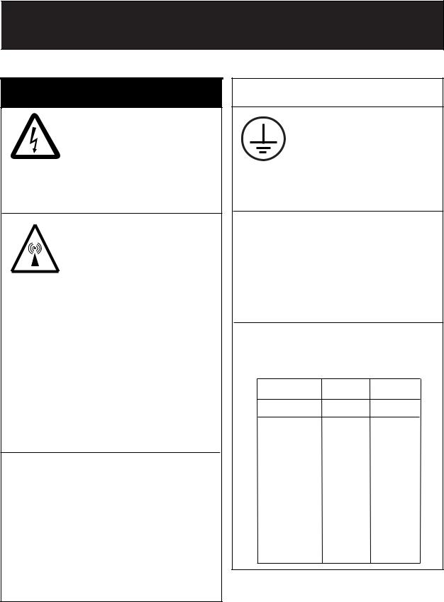
Do not approach the antenna closer than 0.9 m (MPE by FCC) when it is transmitting.
The antenna emits radio waves which can be harmful to the human body.
|
RF power density |
Distance |
Description |
|
on antenna aperture |
|
required by |
|
100 W/m 2 |
0.11 m |
IEC 60945 |
FM-8800S |
|
|
|
10 W/m2 |
0.33 m |
IEC 60945 |
|
|
2 W/m 2 |
0.9 m |
MPE by FCC |
|
100 W/m 2 |
0.11 m |
IEC 60945 |
FM-8800D |
10 W/m2 |
0.33 m |
IEC 60945 |
|
2 W/m 2 |
0.9 m |
MPE by FCC |
(MPE: Minimum Permissible Exposure)
Turn off the power at the mains switchboard before beginning the installation. Post a warning sign near the switchboard to indicate that power should not be applied while the equipment is being installed.
Electrical shock, serious injury or fire can result if the power is not turned off or is applied while the equipment is being installed.
 CAUTION
Attach securely protective earth to the ship's body.
The protective earth (grounding) is required to the AC/DC power supply unit to prevent electrical shock.
Confirm that the power supply voltage is compatible with the voltage rating of the equipment.
Connection to the wrong power supply can cause fire or equipment damage. The voltage rating appears on the label at the rear of the display unit.
Observe the compass safe distance to prevent deviation of a magnetic compass.
|
|
Standard |
Steering |
|
|
|
compass |
compass |
|
|
FM-8800S |
1.45 m |
0.90 m |
|
|
FM-8800D |
1.45 m |
0.95 m |
|
|
|
|
|
|
|
IF-8810 |
0.85 m |
0.55 m |
|
|
|
|
|
|
|
IF-8820 |
0.75 m |
0.50 m |
|
|
|
|
|
|
|
HS-2003 |
1.50 m |
0.95 m |
|
|
|
|
|
|
|
HS-8800 |
0.40 m |
0.30 m |
|
|
|
|
|
|
|
RB-8800 |
1.20 m |
0.80 m |
|
|
(W/HS-8800) |
|
||
|
|
|
|
|
|
|
|
|
|
|
RB-8810 |
1.50 m |
1.00 m |
|
|
(W/HS-8800) |
|
||
|
|
|
|
|
|
PR-240-CE |
0.90 m |
0.60 m |
|
i
TABLE OF CONTENTS
|
|
|
................................................................................SYSTEM CONFIGURATION |
iii |
|
EQUIPMENT LISTS ........................................................................................... |
iv |
|
1. |
MOUNTING ................................................................................................... |
1-1 |
2. |
CONNECTIONS ............................................................................................ |
2-1 |
3. |
ASSEMBLING CONSOLE KIT ..................................................................... |
3-1 |
PACKING LISTS ............................................................................................... |
A-1 |
|
OUTLINE DRAWINGS ...................................................................................... |
D-1 |
|
INTERCONNECTION DIAGRAMS .................................................................... |
S-1 |
|
ii
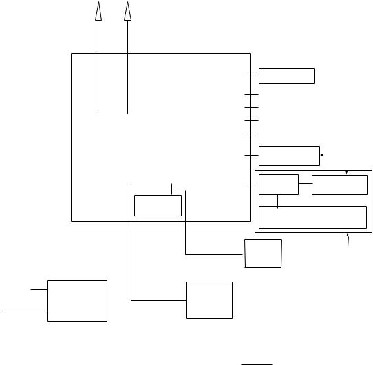
SYSTEM CONFIGURATION
|
|
VHF |
CH 70 RX |
Antenna |
Antenna |
VHF console
|
|
|
|
|
|
|
|
RC-8800 |
|
|
|
|
|
MAX |
|
|
|||
|
|
|
|
|
|
|
|
|
|
|
Wing handset 2 sets |
||||||||
|
|
|
|
|
|
|
|
|
|
|
|
|
|||||||
|
|
|
|
|
|
|
|
|
|
|
|
|
T/R AF output for VDR |
||||||
|
|
|
|
|
|
|
|
|
|
|
Junction |
IEC61162-1 input |
|
|
|||||
|
|
|
|
|
|
|
|
|
|
|
DSC information output |
||||||||
|
|
Handset |
|
|
|
|
|
|
|
||||||||||
|
|
|
|
|
|
|
|
|
|
Box* |
|||||||||
|
|
|
|
|
|
|
|
|
|
|
|
|
|
|
|
|
|||
|
|
HS-2003 |
|
|
|
Transceiver Unit |
|
IF-8810 |
External alarm |
|
|
||||||||
|
|
|
|
|
|
|
|||||||||||||
|
|
|
|
|
|
|
|
FM-8800D |
|
|
|
Remote station |
|
|
MAX |
||||
|
|
|
|
|
|
|
|
|
|
|
|
|
|||||||
|
|
|
|
|
|
|
|
|
|
|
|
|
4 sets |
||||||
|
|
|
|
|
|
|
|
FM-8800S |
|
|
|
RB-8800/8810 |
|||||||
|
|
|
|
|
|
|
|
|
|
|
|
|
|||||||
|
|
|
|
|
|
|
|
|
|
|
DMC I/F |
|
|
|
|
|
|||
|
|
|
|
|
|
|
|
|
|
|
|
|
RB-8800/8810 |
||||||
|
|
|
|
|
|
|
|
|
|
|
|
|
IF-8820 |
||||||
|
|
|
|
|
|
|
|
|
|
|
|
|
|
|
|
|
|
||
|
|
|
|
|
|
|
|
Printer |
|
|
|
|
|
|
|
|
|
|
|
|
|
|
|
|
|
|
|
IF+UTP-80FK |
|
|
|
Distress Message Controller |
|||||||
|
|
|
|
|
|
|
|
|
|
|
|
|
|||||||
|
|
|
|
|
|
|
|
|
|
|
|
|
DMC-5 |
|
|
|
|
|
|
|
|
|
|
|
|
|
|
|
|
|
|
|
Printer |
Omit for Russian Version |
|||||
|
|
|
|
|
|
|
|
|
|
|
|
|
PP-510 |
||||||
|
|
|
|
|
|
|
|
|
|
|
|
|
PP-8800 |
|
|
|
|
|
|
100-115/200-230 VAC |
AC/DC |
|
|
External |
|
|
|
|
|
|
|
||||||||
50/60 Hz, 1φ |
Power Supply |
|
|
|
|
|
|
|
|
|
|
||||||||
|
|
Speaker |
|
|
|
|
|
|
|
||||||||||
Radio Battery |
Unit |
|
|
|
|
|
|
|
|
|
|||||||||
|
|
SEM-21Q |
|
|
|
|
|
|
|
||||||||||
PR-240-CE |
|
|
|
|
|
|
|
|
|
||||||||||
24 VDC |
|
|
|
|
|
|
|
|
|
|
|
|
|||||||
|
|
|
|
|
|
|
|
|
|
|
|
|
|
|
|
|
|||
|
|
|
|
|
|
|
|
|
|
|
|
|
|
: Standard |
|
|
|||
|
|
|
|
|
|
|
24 VDC |
|
|
|
|
|
|||||||
|
|
|
|
|
|
|
|
|
|
|
|
|
|||||||
|
|
|
|
|
|
|
|
|
|
|
|
|
|
|
|
|
|||
|
Category of units |
|
|
|
|
|
|
|
|
|
|
|
: Optional |
|
|
||||
|
|
|
|
|
|
|
|
|
|
|
|
|
|
|
|
|
|
||
|
|
|
|
|
|
|
|
|
|
|
|
|
|
|
|
|
|
||
|
|
Unit |
|
|
|
Category |
|
|
|
|
|
|
|
|
|
|
|
||
|
|
|
|
|
|
|
*: Option for FM-8800S/D-N |
|
|
||||||||||
|
Antenna |
|
|
Exposed to weather |
|
|
|
|
|||||||||||
|
|
|
|
|
|
|
|
|
|
|
|
|
|
|
|
||||
|
All other units |
|
|
Protected from weather |
|
|
|
|
|
|
|
|
|
|
|
||||
|
|
|
|
|
|
|
|
|
|
|
|
|
|
|
|
|
|
|
|
iii

EQUIPMENT LISTS
Standard Supply
|
Name |
Type |
Qty |
Code No. |
Remarks |
|
|
|
FM-8800D-E-A |
|
|
D: Duplex |
|
|
|
FM-8800D-E-N |
|
|
||
|
|
|
|
S: Simplex |
||
|
|
FM-8800D-F-A |
|
|
||
|
|
|
|
E: With handset |
||
|
|
FM-8800D-F-N |
|
|
||
|
|
|
|
HS-2003 |
||
1 |
Transceiver Unit |
FM-8800S-E-A |
1 |
— |
||
F: With microphone |
||||||
FM-8800S-E-N |
||||||
|
|
|
|
DM-2003-F |
||
|
|
FM-8800S-F-A |
|
|
||
|
|
|
|
A: With IF-8810 |
||
|
|
FM-8800S-F-N |
|
|
||
|
|
|
|
N: No IF-8810 |
||
|
|
FM-8800S-R-A |
|
|
||
|
|
|
|
R: Russian version |
||
|
|
FM-8800S-R-N |
|
|
||
|
|
|
|
|
||
|
|
|
|
|
For E-type |
|
|
|
FP05-05700 |
|
000-054-228 |
Handset HS-2003, |
|
2 |
Accessories* |
|
1 |
|
Hanger FP05-05510, |
|
|
|
Others FP05-05511 |
||||
|
|
|
|
|
||
|
|
FP05-05710 |
|
000-054-156 |
For F-type |
|
|
|
|
|
|
Microphone DM-2003-F |
|
3 |
Junction Box |
IF-8810 |
1 |
— |
For A-type |
|
4 |
Installation |
CP05-09900 |
1 |
000-054-227 |
Power cable 05S9371, |
|
|
Materials* |
|
|
|
CP05-09901 |
|
5 |
Spare Parts* |
SP05-05501 |
1 |
005-377-820 |
|
Standard Supply for VHF Console
|
Name |
Type |
Qty |
Code No. |
Remarks |
1 |
VHF Console |
RC-8800-SN |
1 |
— |
D: Duplex FM-8800D |
|
|
RC-8800-DN |
|
|
S: Simplex DM-8800S |
|
|
RC-8800-SA |
|
|
N: No printer |
|
|
RC-8800-DA |
|
|
A: With printer & I/F board |
2 |
Installation |
CP05-10201 |
1 |
005-371-850 |
|
Masteries* |
|
||||
3 |
Accessories* |
FP05-05800 |
1 |
000-054-372 |
Handset HS-2003 & |
|
|
|
|
|
Handset hanger FP05-05510 |
5 |
Spare Parts* |
SP05-05501 |
1 |
005-377-820 |
|
*: See lists at the end of this manual.
iv
|
|
|
|
EQUIPMENT LISTS |
Optional Equipment |
|
|
|
|
|
|
|
|
|
Name |
Type |
Code No. |
|
Remarks |
Flush Mount Kit |
OP05-102 |
000-054-120 |
|
|
Junction Box |
IF-8810 |
— |
|
W/ Screw 5x20 4 pcs. |
DMC Interface |
IF-8820 |
— |
|
No use for Russian version |
|
RB-8800-15 |
|
|
·FP05-05701*, |
|
(W/ 1.5 m Cable) |
|
|
|
|
— |
|
·Handset HS-8800, |
|
|
RB-8800-20 |
|
||
|
|
|
·Hanger W/DIST. button HG-8800 |
|
|
(W/ 2 m Cable) |
|
|
|
Remote Station |
|
|
|
|
RB-8810-15 |
|
|
·FP05-05511*, |
|
|
|
|
||
|
(W/ 1.5 m Cable) |
|
|
|
|
— |
|
·Handset HS-8800, |
|
|
RB-8810-20 |
|
||
|
|
|
·Hanger HG-8810 |
|
|
(W/ 2 m Cable) |
|
|
|
|
|
|
|
|
|
HS-8800-15 |
000-054-230 |
|
W/ 1.5 m Cable |
|
HS-8800-20 |
000-054-171 |
|
W/ 2 m Cable |
|
HS-8800-W-35 |
000-054-287 |
|
Waterproof |
Handset |
HS-2003-15 |
000-054-223 |
|
W/ Cable 1.5 m |
|
HS-2003-20 |
000-XXX-XXX |
|
W/ Cable 2.0 m |
|
HS-2003-50S |
000-XXX-XXX |
|
W/ Straight cable 5.0 m |
|
HS-6000FZ11 |
000-135-072 |
|
|
|
HG-8800 |
000-054-229 |
|
For HS-8800 |
Handset Hanger |
HG-8810 |
000-054-231 |
|
For HS-8800 |
FP05-05510 |
005-951-790 |
|
For HS-2003 |
|
|
|
|||
|
AP-102 |
000-580-019 |
|
For HS-6000FZ11 |
Loudspeaker |
SEM-21Q |
000-144-917 |
|
|
|
|
|
|
Handset HS-6000FZ5, |
Dynamic Mic. Set |
OP05-57 |
000-045-775 |
|
Receptacle RDB-VHF(B), |
|
|
|
|
Hanger AP-102 |
|
|
|
|
Handset HS-6000FZ6, |
Carbon Mic. Set |
OP05-58 |
000-045-776 |
|
Receptacle RDB-VHF, |
|
|
|
|
Hanger AP-102 |
|
|
|
|
Handset HS-6000FZ11, |
Handset set |
OP05-42 |
000-045-778 |
|
Receptacle RDB-VHF(B), |
|
|
|
|
Hanger AP-102 |
Mic. Receptacle Box |
RBD-VHF (B) |
000-056-094 |
|
|
Microphone |
DM-2003-F |
005-377-760 |
|
|
Printer |
PP-510 |
— |
|
|
Printer Interface |
IF-8500 |
— |
|
|
AC-DC Power Supply |
PR-240-CE |
— |
|
|
|
|
|
|
Whip antenna FAB-151D, |
|
AP05-00800 |
000-057-721 |
|
Mounting plate 4-310071, |
|
|
Coax. Cable 5D-2V 10m, |
||
|
|
|
|
|
|
|
|
|
Connector M-P-5 2 PCS |
|
|
|
|
Whip antenna RA106, |
Antenna Material |
AP05-00810 |
000-057-722 |
|
Mounting plate RA115, |
|
|
|
Coax. Cable 05S9104 5m |
|
|
|
|
|
|
|
AP05-00900 |
000-057-739 |
|
Whip antenna 396-1, |
|
|
Mounting plate 4187 |
||
|
|
|
|
|
|
|
|
|
Whip antenna FAB-151D, |
|
AP05-01000 |
000-054-123 |
|
Mounting plate 4-310071, |
|
|
|
|
Connector M-P-7 2 PCS |
|
|
|
*: See lists at the end of this manual |
|
v
EQUIPMENT LISTS
Name |
Type |
Code No. |
Remarks |
|
|
|
|
Whip antenna 150M-W2VN, |
|
|
AP05-01100 |
000-054-224 |
Coax. Cable 5D-2V 10m, |
|
|
|
|
Connector M-P-5 2 PCS |
|
|
|
|
Whip antenna FAB-151D, |
|
|
AP05-01200 |
000-054-232 |
Mounting plate 4-310071, |
|
Antenna Material |
Coax. Cable 5D-2V 10m, |
|||
|
|
|||
|
|
|
Connector M-P-5 & M-P-7 |
|
|
|
|
Whip antenna FAB-151D, |
|
|
AP05-01210 |
000-054-233 |
Mounting plate 4-310071, |
|
|
Coax. Cable 5D-2V 20m, |
|||
|
|
|
||
|
|
|
Connector M-P-5 & M-P-7 |
|
|
05S0309 *10M* |
000-106-043 |
10m |
|
|
05S0309 *20M* |
000-106-044 |
20m |
|
Signal Cable |
05S0309 *30M* |
000-106-046 |
30m |
|
|
05S0309 *40M* |
000-106-047 |
40m |
|
|
05S0309 *50M* |
000-106-048 |
50m |
|
|
|
000-111-680 |
5m |
|
|
CO-SPEVV-SB-C |
000-120-792 |
10m |
|
Twisted Cable |
000-120-793 |
15m |
||
0.2x2P |
||||
|
000-120-794 |
20m |
||
|
|
|||
|
|
000-120-214 |
30m |
|
VHF Console Kit |
RC-8800-N-75BG |
000-054-125 |
Without Printer |
|
RC-8800-A-75BG |
000-054-126 |
With Printer |
||
|
||||
Printer |
PP-8800 |
- |
W/ power cable |
|
Emergency lamp |
EMG-1T |
000-138-378 |
For rack console, cable attached |
vi

1.MOUNTING
Transceiver Unit
General mounting considerations
Determine the mounting location for the transceiver unit considering operator convenience, proximity to the power source and the ground location. Keep these and the following points in mind when selecting a mounting location.
•Locate the unit in a place free of water spray and water splash.
•Keep the unit out of direct sunlight because of heat that can build up inside the unit.
•Leave a little slack in cables to allow a service technician to move the radio from its usual location with the cables connected. This lets him make tuning and other adjustments on a “live” set.
•Do not install the unit where flammable gases are stored.
•Select a well-ventilated area.
•Ensure the mounting location is strong enough to support the weight of the unit (approx. 6 kg) under the condition of continued vibration normally encountered aboard the vessel. If necessary, reinforce the mounting area with a doubling plate or lining block.
•Leave sufficient space at the sides and rear of the unit for maintenance and service purposes and to provide for circulation of cooling air. See outlines drawings at the back of this manual.
•For flush mounting, select a location where the LCD can be easily viewed.
•The transceiver unit will affect a magnetic compass if placed too near the compass. Observe the compass safe distance to prevent deviation of a magnetic compass, referring to page “ i ”.
Note: Take great care not to press the DISTRESS switch during the installation. If you accidentally press the switch, immediately turn off the equipment and contact appropriate authority by telephone.
1-1

1. MOUNTING
Overview of mounting methods
1 2  3 TEST CH16
|
|
|
|
|
4 IntCom |
5 |
ACK |
6 PRINT |
FILE |
|
|
|
|
CANCEL |
7 INTL USA |
8 SCAN |
9 DW |
MENU |
|
|
|
|
|
CALL |
*SHIFT |
0 |
HI/L0 |
LOG |
ENT |
|
|
|
|
MSG |
|||||
|
1 |
2 |
3 TEST |
CH16 |
|
|
|
|
|
|
4 IntCom |
5 ACK |
6 PRINT |
FILE |
|
|
|
|
|
CANCEL |
7 INTL USA |
8 SCAN |
9 DW |
MENU |
|
|
|
|
|
CALL |
*SHIFT |
0 HI/L0 |
LOG |
ENT |
|
|
|
|
|
MSG |
|
|
|
|
|
||||
Overhead Tabletop
DISTRESS
CANCEL
ALM STOP
Keep pressed for 4 s in case of DISTRESS.
The alert is transmitted with steady lighting.
1 |
2 ABC |
3 |
TEST |
CH16 |
DEF |
4 |
IntCom |
5 |
ACK |
6 |
FILE |
|
GHI |
JKL |
MNO |
||||
|
INTL USA |
8 |
SCAN |
|
DW |
MENU |
7 PQRS |
TUV |
9 WXYZ |
||||
CALL MSG |
*SHIFT 0 HI/L0 # LOG |
ENT |
|
|
|
|
|
|
|
|
|
Flush Mount |
Bulkhead |
|
Overview of mounting methods
1-2
1. MOUNTING
Mounting procedure for tabletop, overhead and bulkhead mounting
1.Using the hanger as a template, mark fixing holes in the mounting location.
2.Fix the hanger to the mounting location with self-tapping screws and washers (supplied). (For added support, use nuts, bolts and washers instead of self-tapping screws.)
3.Screw the knob bolts with washers into the transceiver unit.
4.Set the transceiver unit to the hanger and tighten knob bolts.
|
|
265 |
|
|
|
|
|
251 |
|
|
|
|
1 |
2 |
|
3 TEST |
CH16 |
110 |
|
|
|
4 IntCom |
5 |
ACK |
6 PRINT |
FILE |
|
|
ALARM |
|
|
|
|
|
|
|
|
CANCEL |
7 INTL USA |
8 SCAN |
9 DW |
MENU |
||
HANDSET VOL/PWR |
SQL |
CH |
CALL |
*SHIFT |
0 |
HI/L0 |
LOG |
ENT |
|
|
|
MSG |
|||||
OFF |
AUTO |
|
|
|
|
|
||
|
|
|
|
1 |
2 |
|
3 TEST |
CH16 |
|
|
|
|
|
4 IntCom |
5 |
ACK |
6 PRINT |
FILE |
|
100 |
|
|
ALARM |
|
|
|
|
|
100 |
|
|
CANCEL |
7 INTL USA |
8 SCAN |
9 DW |
MENU |
|||
HANDSET VOL/PWR |
SQL |
CH |
CALL |
*SHIFT |
0 |
HI/L0 |
LOG |
ENT |
|
|
|
|
MSG |
|
|||||
OFF |
AUTO |
|
|
|
|
|
|
||
•All dimensions in millimeters.
•Leave sufficient space at the sides and rear of the unit to provide easy access for maintenance and service.
Mounting dimensions for tabletop, overhead and bulkhead mounting
1-3
1. MOUNTING
Mounting procedure for flush mount (option)
Requires optional flush mount kit OP05-102 (Code No. 000-054-120). Prepare a cutout in the mounting location whose dimensions are as shown in the figure below.
Flush mount kit OP05-102
|
|
|
|
Name |
Type |
Code No. |
Qty |
|
1 |
|
|
Mounting plate |
05-093-1211 |
100-323-160 |
1 |
|
2 |
|
|
Self-tapping screw |
5x20 |
000-802-081 |
4 |
|
3 |
|
|
Hex screw |
M8x16 |
000-882-075 |
2 |
20 |
|
|
251 |
#150 |
|
|
|
14 |
27 |
244 |
|
|
|
||
260 ±1
280 ±1
277 ±0.5
105 ±1 30 ±1 |
±0.5 |
|
122 |
Pilot holes (4 pcs.)
Mounting dimensions for flush mount
VHF Antenna
The antenna requirements
Any good quality antenna meeting the requirements shown below may be used. A high-gain antenna is preferable.
• Frequency range: |
155 to 164 MHz |
• Impedance: |
50 ohms |
• Polarization: |
Vertical |
• Handling power: |
30 W/ min |
• Quality: |
Able to withstand marine environment |
Mounting considerations
•The antenna should be well separated from nearby antennas, masts, and other interfering objects.
•The higher the antenna is mounted above the horizon, the further the communications range.
Mounting procedure
The basic mounting procedure for antennas supplied by FURUNO is as follows, however consult appropriate outline drawing for details.
1.Fasten the antenna bracket to the stanchion.
2.Set the antenna to the antenna bracket and tighten bolts.
3.Screw the coaxial cable plug into the antenna.
1-4
1. MOUNTING
CH70 RX Antenna
The antenna should be well separated from nearby antennas, masts, and other interfering objects.
The mounting procedure is the same as that for the VHF antenna, however consult appropriate outline drawing for details.
Handset Hanger
The handset hanger can be mounted at the left side of the transceiver unit. The mounting location should provide easy access to front panel controls while operating the handset. Also, the length of the standard handset cable is 50 cm, so locate the handset hanger within 50 cm of the unit. (Longer cables are available optionally.)
Power Supply (option)
For Convention vessels, both AC and DC power must be fed to the FM-8800D/8800S, via an AC/DC power supply. When AC input fails, DC power is supplied. FURUNO can supply an AC/DC power supply unit, the PR-240-CE.
Mounting considerations
When selecting a mounting location, keep in mind the following points.
•Select a location which provides adequate ventilation.
•The location must be clean and dry.
•The mounting location must be able to support the weight of the unit (14.5 kg) under the continued conditions of vibration normally encountered aboard the vessel. If necessary, reinforce the mounting location.
•The PR-240-CE will affect a magnetic compass if it is placed to near the compass. Observe the compass safe distance to prevent deviation of a magnetic compass, referring to page “ i ”.
Mounting
Refer to outline drawing.
1-5
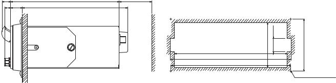
1. MOUNTING
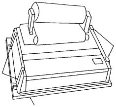
Printer (option)
Printer PP-510
To mount the printer, refer to the printer outline drawing at the back of this manual.
1.Select a flat surface.
2.Fix the mounting base to the mounting location with four screws (supplied).
3.Lay the printer on the top of the mounting base and fasten it with the mounting fixtures (two at each side and one at rear).
Mounting Fixture
Mounting Fixture
Mounting Dimensions 300 (H) x 396 (W) mm
Mounting of Printer PP-510
Printer PP-8800
The printer PP-8800 is flush-mounted in a panel. Refer to the outline drawing at the back of this manual.
1.Make a cutout of 208(w) x 118(h) mm.
2.Set the printer and fix it with four self-tapping screws (4x16).
Printer Interface (option)
The printer interface IF-8500 is required for the printer PP-510 which is commonly used with the FM-8800D/S and other MF/HF radio communication equipment. To mount the unit, see the outline drawing at the back of this manual.
External Loudspeaker (option)
The external loudspeaker can be installed on a tabletop, the overhead or a bulkhead. Fasten the loudspeaker to the mounting location with self-tapping screws, or nuts, bolts and washers. For mounting dimensions, see the outline drawing at the back of this manual.
1-6
1. MOUNTING
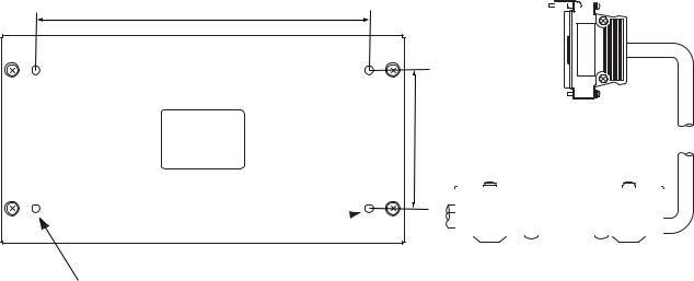
Junction box IF-8810/ DMC interface IF-8820
Note: DMC interface IF-8820 is not used for Russian version.
To install the remote box RB-8800/RB-8810, wing handset, etc., the junction box IF-8810 is required. Install the junction box near the transceiver unit. Approx. 3 m cable is preattached to the junction box to connect to the transceiver unit.
To connect Furuno’s distress message controller DMC-5, the DMC interface IF-8820 (option) is required.
1.Open the cover.
2.Mount the unit with four self-tapping screws (5x20).
240
100 |
Note: This plug is not |
|
|
fitted in IF-8820. |
|
|
|
|
|
|
|
Fixing holes 5mm dia.
Mounting the junction box/DMC interface
1-7

1. MOUNTING
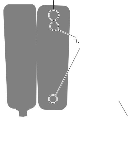
Remote station RB-8800/RB-8810 (option)
Up to four remote stations can be connected in a daisy chain.
Note: For the remote station RB-8800, there are two method of cable entry: bottom-side entry and rear-side entry. For rear-side entry, make one or two holes of more than 12 mm diameter. For last station in the daisy chain, just one cable entry hole is needed.
1.Remove screws on the handset hanger (four for RB-8800, six for RB-8810).
2.Remove upper chassis of the hanger.
3.Mount the base of the hanger to a bulkhead with self-tapping screws 4x20 (four for RB-8800), or 4x16 (two for RB-8810).
4.After connecting cables, assemble the remote station.
5.For RB-8800, attach blind seals on the screws.
entry |
|
Cable |
φ |
|
12 |
|
12 |
|
φ |
#150
77 |
Handset |
|
|
|
|
|
|
|
|
|
|
|
|
|
|
|
HS-8800 |
Screws 4 pcs. |
|
|
|
|
|
|
|
Attach blind seal |
20 30 |
|
Cover of handset hanger |
||
|
|
on the screws. |
|
|
|||
|
Handset hanger |
63 |
|
|
|
33 |
|
|
HG-8800 |
|
|
|
|
|
Nameplate |
|
|
|
|
|
|
|
|
|
|
|
40 |
|
|
|
0.5 |
|
|
|
|
|
|
|
± |
|
|
|
|
|
|
DISTRESS |
140 |
|
|
Cable entry |
|
|
|
|
|
|
|
(Rear) |
|
|
|
VOLUME |
|
|
|
|
|
|
|
|
4-φ4.5 |
|
|
|
|
|
|
|
Fixing holes |
|
|
|
|
40±0.5 |
40 |
±0.5 |
Cable entry |
|
|
|
|
|
|
|
|
(Bottom)
|
Remote station RB-8800 |
|
||
|
Hanger |
|
|
|
|
HG-8810 |
Handset |
|
|
|
|
|
|
|
|
(77) |
HS-8800 |
|
|
|
57 |
|
|
|
|
12,Cableentry |
65 |
|
Cable entry |
(208) |
Nameplate |
22 |
0.5 42 |
|
|
|
|
|
|
|
φ |
208 |
|
145 |
|
|
|
|
± |
#150 |
|
|
2-φ4.5 |
|
|
|
|
|
|
|
|
|
|
Fixing hole |
|
|
Hanger |
Hanger mounting base |
|
Remote station RB-8810
1-8
1. MOUNTING
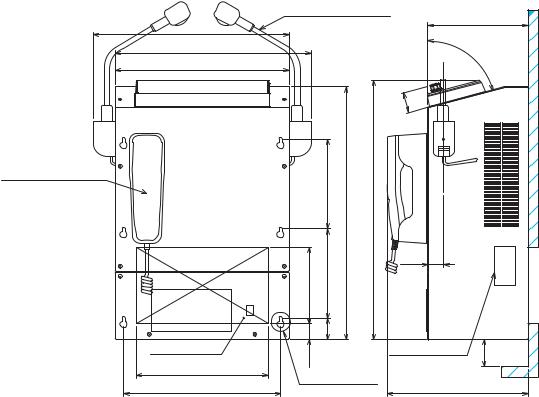
Outdoor mounting of RB-8810
Remote station RB-8810 with waterproof-type handset HS-8800-W-35 can be mounted outdoors. The hanger should be coated as directed below with silicone sealant for waterproofness.
1.Fix the mounting base with self-tapping screws. Coat exposed part of these screws with silicone sealant.
2.Attach the cable from the transceiver unit or junction box. Coat cable around cable entrance with silicone sealant
3.Fix the cover of the handset hanger. Coat junction between mounting base and cover with silicone sealant.
2. All around the cable at cable entry
Self-tapping screws
3. All around the junction coating parts
Note: Confirm that plastic washers are  in screw holes before fixing cover.
1-9
1. MOUNTING
VHF console
Install the rack console where the equipment can be easily operated, checked and serviced. Consult with shipyard personnel and ship's officer-in-charge to determine best location. The location must satisfy the following points:
•Select a location where controls can be easily operated.
•Select a location where shock and vibration are minimal.
•Locate the console away from water splash and rain.
•The temperature and humidity of the location should be both stable and moderate.
Fixing
1.Ask shipyard personnel to tighten six M5 nuts or six M5 bolts to the fixing holes (on the wall), referring to the outline drawing at the back of this manual.
2.Detach the cover assembly from the console.
3.Hang VHF console on bolts.
4.Screw the console with the bolts or nuts tightly.
5.Attach the cover assembly to the console.
Note: When you connect wires as soon as attaching console, refer to paragragh 2-10.
6.Attach the handset hanger with two screws.
7.To attach the optional emergency lamp, connect the cable to the terminal board, and then attach the lamp to the console. Refer to the interconnection diagram and out line drawing.
HANDSET HANGER
|
EMG-1T |
190 |
|
(371) |
EMERGENCY LAMP |
||
|
|||
(371) |
|
75 |
|
|
|
||
330 |
|
° |
|
|
|
||
|
|
40 |
|
|
170 ± 0.5 |
480 |
(500) |
|
|
|
145 1700.5± |
|
30 |
|
|
|
|
|
|
|
|
|
40 |
|
|
|
CABLE ENTRY |
30 |
|
TERMINAL BOARD |
#50 |
|
(REAR) |
250 |
|
|
||
FIXING HOLES |
|
||||
|
|
|
|||
298 ± 0.5 |
|
|
(266) |
|
|
1-10
2.CONNECTIONS
Overview
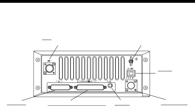
The figure below shows where to connect various equipment at the rear of the transceiver unit.
ANT |
|
Connects antenna. |
Ground terminal. |
24VDC Connects power cable.
PRINTER |
IEC61162-1 (NMEA)/REMOTE |
EXT SP |
CH70 RX ANT |
Connects printer |
Connects junction box IF-8810. |
Connects external |
Connects DSC |
PP-510. |
|
loudspeaker. |
antenna here. |
FM-8800D/8800S, rear view
Connection of Power Supply
Convention vessels, 100/220 VAC ship’s mains
Convention vessels must supply both AC and DC power to the FM-8800D/8800S, via an AC/DC power supply unit. Both AC and DC are supplied by the AC/DC power supply unit, and when AC input fails DC power is activated.
Connect the radio battery to the DC IN terminal on the PR-240-CE. Connect the AC ship’s mains to the AC IN terminal on the PR-240-CE.
Radio battery (24 VDC)
Attach the connector supplied to the power cable and plug it into the 24VDC connector at the rear of the transceiver unit. Connect the wire ends to the radio battery line.
2-1
2. CONNECTIONS
Connection of VHF Antenna
The VHF antenna is connected to the transceiver unit with a 50 ohm coaxial cable, type 5D-2V. Be sure to leave some slack in the cable for future service and maintenance.
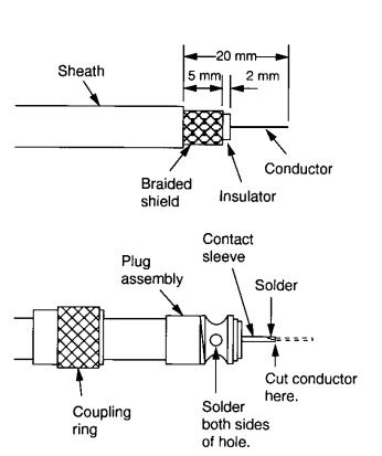
Lay the coaxial cable and attach an M-type plug to the cable (if necessary) as follows.
1.Remove the sheath by 20 mm.
2.Bare 13 mm of the center conductor. Trim braided shield by 5 mm and tin.
3.Slide coupling ring onto cable.
4.Screw the plug assembly on the cable.
5.Solder plug assembly to braided shield through solder holes. Solder contact sleeve to conductor.
6.Screw coupling ring into plug assembly.
7.Screw the plug into the ANT connector at the rear of the transceiver unit.
How to attach the M-type plug to the coaxial cable
2-2
2. CONNECTIONS
Connection of DSC Antenna
The DSC antenna is connected to the transceiver unit with a 50 ohm coaxial cable, type 5D-2V. Attach an M-type plug to the cable (if necessary) as shown an page 2-2. Screw the plug into the CH70 RX ANT connector at the rear of the transceiver unit.
Connection of Handset
Connect the handset cable to the HANDSET connector on the front panel.
Grounding the Transceiver Unit
Fasten a ground wire (local supply) between the GND terminal at the rear of the transceiver unit and ship’s hull (or ground bus).
Connecting the Junction Box
The junction box is required to connect a remote station, wing handset, etc. The cable to be connected with the transceiver unit is prefitted on the junction box at the factory. For connection of other cables, see the interconnection diagram.
Cable entry |
Clamp the cable with |
|
U-type cable clamps. |
||
|
Use one of these nuts for ground terminal between JB and ship's body.
Cable clamp: Clamp shield part of the cables to ground cables.
2-3
Loading...