


 Loading...
NAVIGATIONAL ECHO SOUNDER
FE-700

9-52 Ashihara-cho,
Nishinomiya 662-8580, JAPAN
Telephone : |
0798-65-2111 |
|
Fax |
: |
0798-65-4200 |
All rights reserved. |
Printed in Japan |
Pub. No. OME-23660
( YOSH ) FE-700
Your Local Agent/Dealer
FIRST EDITION : JAN. 2000
Q : DEC. 15, 2004
*00080890804*
*00080890804*
* 0 0 0 8 0 8 9 0 8 0 4 *
*OME23660Q00*
*OME23660Q00*
* O M E 2 3 6 6 0 Q 0 0 *

 SAFETY INSTRUCTIONS
 WARNING
ELECTRICAL SHOCK HAZARD
Do not open the equipment.
Only qualified personnel should work inside the equipment.
Immediately turn off the power at the switchboard if water leaks into the equipment.
Continued use of the equipment can cause fire or electrical shock. Contact a FURUNO agent for service.
Do not disassemble or modify the equipment.
Fire, electrical shock or serious injury can result.
Immediately turn off the power at the switchboard if the equipment is emitting smoke or fire.
Continued use of the equipment can cause fire or electrical shock. Contact a FURUNO agent for service.
Make sure no rain or water splash leaks into the equipment.
Fire or electrical shock can result if water leaks in the equipment.
Use the proper fuse.
Use of a wrong fuse can result in equipment damage and void the warranty.
 CAUTION
Do not power the equipment when the transducer is in air.
The transducer may become damaged.
WARNING LABEL
A warning label is attached to the equipment. Do not remove the label. If the label is missing or illegible, contact
a FURUNO agent or dealer.
WARNING |
Name: Warning Label (1) |
|
Type: 86-003-1011-1 |
||
To avoid electrical shock, do not |
||
remove cover. No user-serviceable |
Code No.: 100-236-231 |
|
parts inside. |
|
 About the TFT LCD
The TFT LCD is constructed using the latest LCD techniques, and displays 99.99% of its pixels. The remaining 0.01% of the pixels may drop out or blink, however this is not an indication of malfunction.
i
RECORD OF MODIFICATIONS IN THIS OPERATOR’S MANUAL
Pub No. |
Software (Prog No.) |
Outline of changes in Operator’s manual |
|
|
|
|
|
Publicized for |
Display Unit |
displayed at switch-on |
|
submission to |
02522970-01 |
(Subject to change by the type approval authorities.) |
|
type test by BSH |
|||
(Feb/2000) |
Digital Depth Indicator |
(Subject to change by the type approval authorities.) |
|
65-5-0100-001 |
|||
|
|||
|
|
||
OME-23660-F |
Digital Depth Indicator |
Changed [Unit] key to [*] and the related part of software. |
|
Dec/2000 |
65-5-0100-003 |
|
|
|
|
|
|
OME-23660-G |
Display Unit |
Added TRANSDUCER SETTING option in the |
|
Apr/2001 |
02522970-02 |
EXTENSION MODE menu. |
|
Added KEEL DISTANCE option in the SYSTEM MENU3. |
|||
|
(Serial no. 2232-0618 and |
||
|
|
||
|
after) |
|
|
|
|
|
|
OME-23660-H |
---- |
Modified errors. |
|
May/2001 |
|
|
|
|
|
|
|
OME-23660-K |
Display Unit |
Modified to conform with IEC 61162-1 Edition 2. |
|
Apr/2002 |
02522970-03 |
|
|
|
|
||
|
|
|
|
OME-23660-Q |
Display Unit |
Deleted KEEL DISTANCE option in the SYSTEM |
|
Dec/2004 |
02522970-04 |
MENU3. |
|
|
|
Changed draft setting range from “0 to 30 m” to “-10 to |
|
|
|
30 m”. |
|
|
|
|
ii

CONTENTS
FOREWORD ......................................... |
iv |
||
|
A Word to FE-700 Owners........................... |
iv |
|
|
Features ..................................................... |
iv |
|
SYSTEM CONFIGURATION .................. |
v |
||
SPECIFICATIONS OF FE-700 ….....SP-1 |
|||
1 |
OPERATION ..................................... |
1 |
|
|
1.1 |
Control Description................................ |
1 |
|
1.2 |
Indications, Markers.............................. |
2 |
|
1.3 |
Turning On/Off ...................................... |
3 |
|
1.4 |
Tone and Brilliance................................ |
3 |
|
1.5 |
Panel Dimmer ....................................... |
3 |
|
1.6 |
Display Mode ........................................ |
4 |
|
1.7 |
Range Scale ......................................... |
7 |
|
1.8 |
Gain Control.......................................... |
7 |
|
1.9 |
Automatic Operation ............................. |
7 |
|
1.10Picture Colors ....................................... |
7 |
|
|
1.11Shallow Depth Alarm............................. |
8 |
|
|
1.12Draft...................................................... |
8 |
|
2 |
MENU OPERATION.......................... |
9 |
|
|
2.1 |
Menu Overview..................................... |
9 |
|
2.2 |
Suppressing Low Level Noise ............... |
9 |
|
2.3 |
Suppressing Interference ...................... |
9 |
|
2.4 |
Picture Advance.................................. |
10 |
|
2.5 |
Trend .................................................. |
10 |
|
2.6 |
Interval................................................ |
10 |
3 |
SYSTEM MENU .............................. |
11 |
|
|
3.1 |
System Menu...................................... |
11 |
|
3.2 |
System Menu 1................................... |
12 |
|
3.3 |
System Menu 2................................... |
12 |
|
3.4 |
System Menu 3................................... |
13 |
4 |
ECHO QUALITY SETTING............. |
14 |
|
|
4.1 |
Demonstration Display........................ |
14 |
|
4.2 |
Transducer Setting.............................. |
14 |
|
4.3 |
Bottom Level....................................... |
15 |
|
4.4 |
TVG Level .......................................... |
15 |
|
4.5 |
Echo Offset......................................... |
15 |
5 |
OPERATION OF DIGITAL DEPTH |
|
|
|
INDICATOR FE-720 (OPTION) ....... |
16 |
|
|
5.1 |
Basic Operation................................. |
16 |
|
5.2 |
Menu Operation ................................ |
17 |
|
5.3 |
Diagnosis .......................................... |
18 |
|
5.4 |
Factory Setting.................................. |
18 |
6 |
MAINTENANCE, |
|
|
|
TROUBLESHOOTING .................... |
19 |
|
|
6.1 |
Checking ............................................ |
19 |
|
6.2 |
Cleaning the Display Unit.................... |
19 |
|
6.3 |
Transducer Maintenance..................... |
19 |
|
6.4 |
Replacing the Fuse, Battery................ |
19 |
|
6.5 |
Troubleshooting .................................. |
20 |
|
6.6 |
Diagnostic Test ................................... |
21 |
|
6.7 |
Test Pattern ........................................ |
21 |
|
6.8 |
Clearing the Memory........................... |
22 |
7 |
MENU TREE ................................... |
23 |
|
8 |
DIGITAL INTERFACE (IEC 61162-1 |
||
|
EDITION 2) ..................................... |
24 |
|
9 |
PARTS LOCATION, PARTS LIST ..32 |
||
Declaration of Conformity
iii

FOREWORD
A Word to FE-700 Owners
Thank you for purchasing this navigational echo sounder. We are confident you will discover why FURUNO has become synonymous with quality and reliability.
Dedicated in the design and manufacture of marine electronics equipment for half a century, FURUNO Electric Company has gained an unrivaled reputation as a world leader in the industry. This is the result of our technical excellence as well as our worldwide distribution and service network.
Please carefully read and follow the safety information and operating and maintenance instructions set forth in this manual before attempting to operate the equipment and conduct any maintenance. Your navigational echo sounder will perform to the utmost of its ability only if it is operated and maintained in accordance with the correct procedures.
This equipment is designed, produced and documented by FURUNO ELECTRIC CO., LTD., complying with ISO 9001 standards as certified by the Lloydís Register of Quality Assurance System.
Features
The FURUNO FE-700 is comprised of display unit and transducer unit. Echo sounding data is displayed on the bright 6.5-inch color TFT (Thin Film Transistor) LCD display.
The main features of the FE-700 are
1.Complies with the IMO and ISO standards
MSC.74(69) Annex 4 and ISO9875.
2.Cost-effective; no paper, no consumables; high accuracy and high reliability - no rotating gears and belts as in the paper echo sounders
3.High-contrast 6.5-inch color LCD display featuring a wide viewing angle and adjustable brightness.
4.Wide variety of modes with never-get-lost default position.
5.Automatic function permits unattended adjustment of range, gain, and pulselength. The range scale and gain automatically change to display the bottom.
6.Position, course, speed, time are repeated from the external devices.
7.Alarms: shallow water, bottom lost, power drop
iv
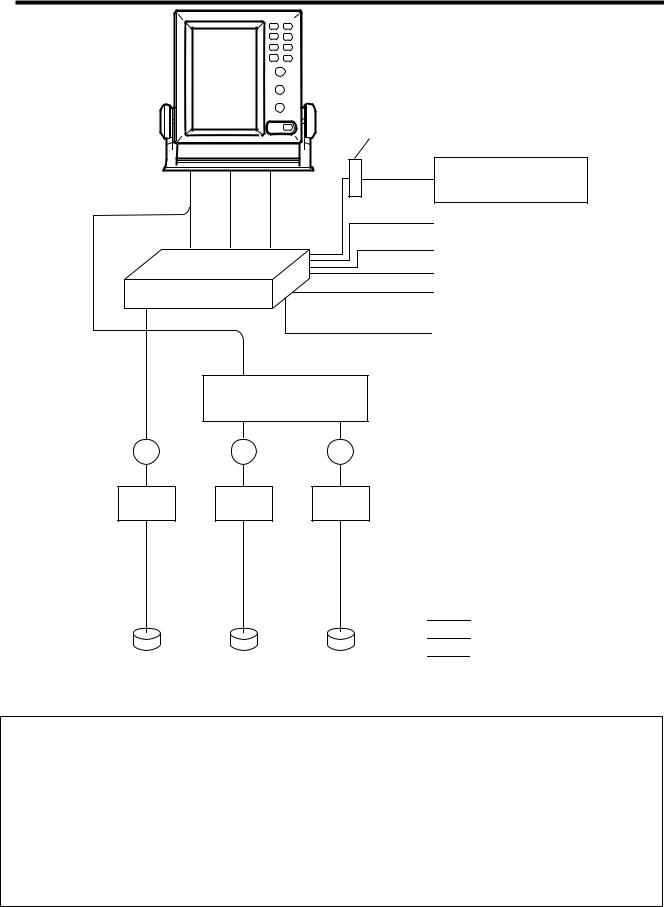
SYSTEM CONFIGURATION
DISPLAY UNIT
FE-701
|
TERMINAL BOX |
|
|
DS-802 |
|
|
IEC 61162-1 |
DIGITAL DEPTH INDICATOR |
|
|
|
|
|
FE-720 |
DISTRIBUTION |
IEC 61162-1 |
Navigation Device |
|
||
BOX |
IEC 61162-1 |
Navigation Device |
FE-702 |
|
|
EIA-232C |
|
|
|
Personal Computer |
|
|
CONTACT CLOSURE |
|
|
Alarm Unit |
|
|
|
|
|
|
Ship’s mains |
|
|
100-115 VAC/200-230 VAC |
|
|
or |
|
|
24 VDC |
TRANSDUCER SWITCH BOX
EX-8
JB |
JB |
JB |
JUNCTION BOX |
|
JIS F8821-1 |
||||
|
|
|
MATCHING BOX MB-502 (for 50B-6B)
MB-504 (for 200B-8B)
: Standard Supply
: Optional Supply
: Local Supply
TRANSDUCER
FE-700 system configuration
PRINCIPLE OF OPERATION
The FE-700 uses ultrasonic pulses to detect the seabed and other underwater objects. The display unit contains all basic electric circuits and logic processor. Electrical pulses are converted into acoustical energy in the transducer fitted on the ship’s hull. The processor measures the time of pulses travelling between the seabed and transducer and displays the water depths in the graphical form or other forms.
The transducers have a specific beam width with respect to their working frequency, 50 kHz or 200 kHz. The high frequency has a narrow beamwidth and is immune to aeration when the ship is going astern or in rough weather. The low frequency has a wide beamwidth and more powerful sounding capability.
v
SPECIFICATIONS OF NAVIGATIONAL ECHO SOUNDER
FE-700
1 |
DISPLAY UNIT |
|
1.1 |
Graphical Display |
6.5-inch color TFT LCD, 320 x 234 pixels |
1.2 |
Echo Colors |
8 colors or 8 level monochrome |
1.3 |
Display Area |
133 x 97 mm |
1.4Basic Display Range
Unit |
|
|
|
Range |
|
|
|
||
1 |
2 |
3 |
4 |
5 |
6 |
7 |
8 |
||
|
|||||||||
Meters |
5 |
10 |
20 |
40 |
100 |
200 |
400 |
800 |
|
Feet |
15 |
30 |
60 |
120 |
300 |
600 |
1500 |
2500 |
|
Fathoms |
3 |
5 |
10 |
20 |
50 |
100 |
200 |
400 |
|
|
|
*Default settings; it could be customized for use w/o range 3 and 6. |
1.5 |
Accuracy |
±2.5% on any range |
1.6 |
Minimum Range |
0.5 m (200 kHz), 2.0 m (50 kHz) |
1.7 |
Draft |
-10 to 30 m in 0.1 m steps, default 0 m |
1.8Pulse Repetition Rate (PRR)
|
|
|
Depth (m) |
P/L (ms) |
PRR (pulse/min) |
|
|
|
|
|
|||||
|
|
|
5, 10, 20 |
|
0.25 |
|
750 |
|
|
|
|
|
|||
|
|
|
40 |
|
0.38 |
|
375 |
|
|
|
|
|
|||
|
|
|
100 |
|
1.00 |
|
150 |
|
|
|
|
|
|||
|
|
|
200 |
|
2.00 |
|
75 |
|
|
|
|
|
|||
|
|
|
400,800 |
|
3.60 |
|
42 |
|
|
|
|
|
|||
1.9 |
Display Mode |
|
“NAV”: Basic echo presentation with the depth below transducer |
||||||||||||
|
|
|
“DBS”: Echo presentation with the depth below sea surface (or keel) |
||||||||||||
|
|
|
“HISTRY”: Historical Echo presentation with the depth |
|
|
||||||||||
|
|
|
“LOGBOOK”: Echo presentation with the pop-up table showing |
||||||||||||
|
|
|
Time, Depth and L/L* data memorized at preset interval |
||||||||||||
|
|
|
“OS DATA”: Echo presentation with the pop-up table of present |
||||||||||||
|
|
|
navigational data; L/L*, course*, speed*, time, depth |
||||||||||||
|
|
|
“HELP”: Echo presentation with the help menu and note |
|
|
||||||||||
|
|
|
“MENU”: Echo presentation with the user menu |
|
|
||||||||||
1.10 |
Picture Advance Speed |
|
|
|
|
|
|
|
|
|
|
|
|
||
|
Slow mode |
|
15 minutes or more |
|
|
|
|
|
|
|
|
||||
|
Fast mode |
|
Picture advance range |
|
|
|
|
|
|
|
|
||||
|
|
Range (m) |
5 |
|
10 |
|
20 |
40 |
100 |
200 |
400 |
|
800 |
||
|
|
Interval (min.) |
|
1.8 |
|
|
8 |
20 |
|
30 |
|||||
SP - 1 |
E2366S01Q |
1.11 |
User Setting |
Gain, Range, Alarm, Draft, Brilliance, Dimmer, Color, Auto |
1.12 |
Auto Set Mode |
Gain, range and clutter will be automatically adjusted. |
1.13 |
Alarm |
Shallow water (default 20 m), Bottom lost, Power drop |
1.14 |
Logbook Display |
Depth, Internal clock, L/L* |
|
|
1 hour at 5 sec Interval, 12 hours at 1 minute interval and 24 |
|
|
hours at 2 minutes interval |
|
|
*: External navigational sensor required. |
2 |
TRANSCEIVER CHARACTERISTICS (BUILT IN DISPLAY UNIT) |
|
2.1 |
Transmit Frequency |
50 kHz or 200 kHz |
2.2 |
Output Power |
600 Wrms |
3 |
DIGITAL DEPTH INDICATOR |
|
3.1 |
Display |
4.5-inch monochrome LCD |
3.2 |
Depth Indication |
**.* m (less than 100m) |
|
|
**** m (100 m or more) |
3.3 |
Power supply |
24 VDC, 150mA |
3.4 |
Coating color |
Panel: N3.0, Chassis: 2.5GY5/1.5 |
3.5 |
Waterproofing |
IPX5 |
4 |
TRANSDUCER TYPE AND BEAMWIDTH |
|
4.1 |
50B-6B (50 kHz): |
35° |
4.2 |
200B-8B (200 kHz): |
6° |
5 |
INTERFACE |
|
5.1 |
Serial Input Data |
IEC61162-1, current loop; 1 port |
|
|
RMA: L/L, ground track speed, Track |
|
|
RMC: L/L(GPS), ground track speed, Track, Time |
|
|
GLL: L/L |
|
|
GGA: L/L |
|
|
VTG: Ground track speed, |
|
|
Track (True/Magnetic selected on menu) |
|
|
ZDA: Time |
5.2 |
Serial Output Data |
IEC61162-1, output period: 1 sec.; 3 outputs/ |
|
|
1 port |
|
|
SDDPT: Depth (m), Draft (m) |
|
|
SDDBT: Depth (ft, m, fa) below transducer |
|
|
SDDBS: Depth (ft, m, fa) below sea surface |
5.3 |
Serial I/O Data |
RS-232C, 1 port |
|
Output |
Depth, clock, L/L, ship’s speed, course |
SP - 2 |
E2366S01Q |
|
Input |
Control command for PC |
5.4 |
Alarm (Depth, Power) |
Contact closure signal, normal open or normal close, |
|
|
250 VAC/ 200 VDC, 3A max. |
6 |
POWER SUPPLY |
|
|
|
24 VDC (-10%, +30%): 20W or |
|
|
100-115/200-230 VAC, 1 phase, 50/60Hz: 20VA. |
7 |
ENVIRONMENTAL CONDITION |
|
7.1 |
Temperature |
-15 °C to +55 °C |
7.2 |
Relative Humidity |
93% or less at 40 °C |
7.3 |
Waterproofing |
Display Unit: IEC IPX5 |
|
|
Distribution Box: IEC IPX2 |
|
|
Matching Box: IEC IPX2 |
7.4 |
EMC Emission |
IEC 60945 Ver.3 |
7.5Category of Equipment Units
|
Display Unit |
protected from the weather |
|
Distribution Box |
protected from the weather |
|
Matching Box |
protected from the weather |
|
Transducer |
Submerged area |
8 |
COATING COLOR |
|
8.1 |
Display Unit |
Panel: N3.0, Chassis: 2.5GY5/1.5 |
8.2Distribution Box/ Matching Box
2.5GY5/1.5
SP - 3 |
E2366S01Q |

1OPERATION
1.1 Control Description
All operation of the FE-700 is carried out with the controls on the front panel of the display unit. Rotary controls respond immediately to your command but some touch keys require the successive operation.
•
• 


• 


1
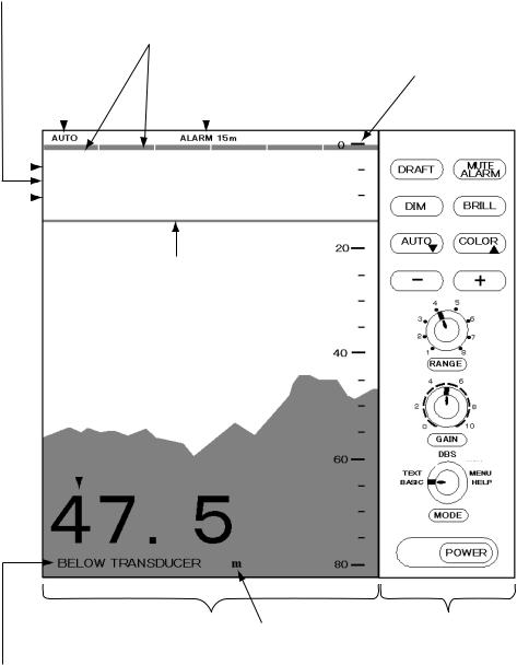
1.2 Indications, Markers
Display mode |
|
|
|
|
|
||||||
|
Gain setting |
|
|
|
|
|
|||||
|
|
|
|
|
|
||||||
|
Range setting |
Transducer in use ( when using |
|
||||||||
|
|
|
Auto |
transducer switch box. ) |
|
||||||
|
|
|
|
||||||||
|
|
|
|
Alarm |
Range scale |
||||||
|
|
|
mode |
|
setting |
|
|||||
|
|
|
|
|
|
|
|
|
|
|
|
|
|
|
|
|
|
|
|
|
|
|
|
|
|
|
|
|
|
|
|
|
|
||
|
|
|
|
AUTO |
|
ALARM 15m |
|
|
|||
|
|
|
|
FORE |
50kHz |
|
|||||
|
|
|
|
RANGE: 4 |
|
|
|
|
|
||
|
|
|
|
|
|
|
|
||||
|
|
|
|
GAIN: 5.5 |
|
|
|
|
|
||
|
|
|
|
MODE: NAV |
|
|
|
|
|
||
|
|
|
|
|
|
|
|
||||
Depth alarm line
Depth |
|
|
|
|
LOGBOOK |
|
|
|
|
HISTORY |
|
OS DATA |
|||||
|
|
DBS |
|
|
|
HELP |
||
|
|
|
|
|
|
|||
|
|
|
|
|
|
|
|
|
|
|
|
NAV |
|
|
|
MENU |
|
|
|
|
|
|
|
|
|
|
Screen |
Depth unit |
Control panel |
Explanation of depth (Below transducer, or below surface)
2

1.3 Turning On/Off |
1.4 Tone and Brilliance |
1.Turning on: Press the POWER Switch. Self-test starts, showing the condition of the logic circuits. The program number is displayed.
ROM: OK
DRAM: OK
SRAM: OK
BATTERY: OK
PROGRAM NO. 0252297002
2.Select a mode with the MODE Selector. The NAV position of the selector is recommended for general use. Display color is amber by default but may be customized. The unit of measurement is meters. You can freely select another mode at any time.
3.Turning off: Press the POWER Switch again.
Wait at least 5 s before reapplying the power.
Note: When two transducers are installed, make sure which transducer is used.
Note: When lat/long data input error occurs, “EPFS” ERROR appears on the screen. (EPFS: Electronic Position-Fixing System such as GPS receiver)
1. |
Press the BRILL key. The tone and brilliance |
||||
|
setting window appears. |
|
|
||
|
|
|
|
|
|
|
|
|
LOW ▼ |
▲ HIGH |
|
|
|
BRILL: |
8 |
|
|
|
|
|
LOW - |
+ HIGH |
|
|
|
TONE: |
3 |
|
|
2. |
|
|
|
||
Press the [+] or [-] key for desired tone (in |
|||||
|
reality, Contrast). |
|
|
||
3. |
Press the [▲] or [▼] key for desired |
||||
|
brilliance. Pressing the BRILL key also |
||||
|
changes the brilliance from minimum to |
||||
|
maximum and vice-versa. |
|
|
||
Note: Tone or brilliance must be adjusted within 10 seconds after pressing the BRILL key. Otherwise the tone and brilliance window will be erased.
1.5 Panel Dimmer
1.Press the DIM key. The panel dimmer setting window appears.
LOW - + HIGH
DIMMER: 5
2.Press the [+] or [-] key for desired illumination of the control panel. Pressing DIM key also changes the illumination level.
3
1.6 Display Mode
The Mode Selector choose the display mode among NAV, DBS (depth below surface), HISTORY, LOGBOOK, OS DATA, HELP, and MENU.
 CAUTION
DBS is not a water clearance below keel.
Do not use this mode in shallow waters to avoid grounding.
1.6.1NAV mode
The depth from the transducer to the seabed (bottom clearance) is shown on the screen. Note “BELOW TRANSDUCER” appears at the bottom of the screen in this mode.
Default is, |
|
Color: |
Amber |
Range: |
Automatic range switching |
Window: |
15 minutes |
Shallow depth alarm: 20 m
NOTE: These parameters can be customized to your preference and the last setting is used at a next switch-on. This is true on all other modes.
1.6.2DBS mode
The Depth Below Surface mode provides a draft-adjusted depth reading and will be useful in referencing to the nautical chart. The draft should be adjusted by the DRAFT key according to the actual draft value. If you find any difficulty to check for the draft value, use the NAV mode.
When the DBS mode is selected, the message “Confirm and set ship’s draft to use DBS mode” appears. Confirm ship's draft and set it by referring to section 1.12.
BELOW KEEL (when the draft setting is –10.0 to –0.1) or BELOW SURFACE (when the draft setting is 0 to 30.0) appears at the bottom of the display and the draft value appears at the upper right-hand corner in the DBS mode.
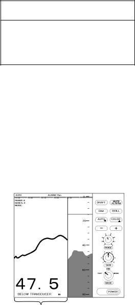
1.6.3HISTORY mode
This mode provides a mix of Contour and Strata displays. The Contour display can be scrolled over the past 24 h while the right side Strata display (layers of different colors according to reverberation strengths) shows the latest sounding for 5 minutes.
Pressing the [+] or [-] key moves the Contour display forwards or backwards, respectively.
HISTORY
|
|
|
LOGBOOK |
|
|
|
|
HISTORY |
|
|
|
OS DATA |
|
||
|
|
|
|
|
|
|
|
|
DBS |
|
|
|
|||
|
|
|
|
|
HELP |
||
|
NAV |
MENU |
|||||
History of the bottom
If the range scale for both the Contour and Strata display must be the same. If they are not, the message “OUT OF RANGE” appears.
The update of the contour data may take max. one minute. Wait for one minute to display accurate contour if you change the range scale.
4
Loading...