


 Loading...

IMPORTANT NOTICE
•No part of this manual may be copied or reproduced without written permission.
•If this manual is lost or worn, contact your dealer about replacement.
•The contents of this manual and equipment specifications are subject to change without notice.
•The example screens (or illustrations) shown in this manual may not match the screens you see on your display. The screen you see depends on your system configuration and equipment settings.
•This manual is intended for use by native speakers of English.
•FURUNO will assume no responsibility for the damage caused by improper use or modification of the equipment or claims of loss of profit by a third party.
•Please carefully read and follow the operation, installation and maintenance procedures set forth in this manual.
•Store this manual in a convenient place for further reference.
i
 SAFETY INSTRUCTIONS
Safety Instructions for the Operator
 WARNING
Do not open the equipment.
There are no user-serviceable parts inside.
Do not disassemble or modify the equipment.
Fire, electrical shock or serious injury can result.
Immediately turn off the power at the switchboard if the equipment is emitting smoke or fire.
Continued use of the equipment can cause fire or electrical shock. Contact a FURUNO agent for service.
Do not maneuver the vessel based on the depth indication alone.
Grounding may result.
Use the proper fuse.
Fuse rating is shown on the equipment. Use of a wrong fuse can result in damage to the equipment.
 CAUTION
Do no turn on the equipment with the transducer out of water.
The transducer may be damaged.
The picture is not refreshed when picture advancement is stopped.
Maneuvering the vessel in this condition may result in a dangerous situation.
Use the proper gain setting.
Incorrect gain may produce wrong depth indication, possibly resulting in a dangerous situation.
NOTICE
A warning label is attached to the equipment. Do not remove the label. If the label is missing or damaged, contact a FURUNO agent or dealer about replacement.
WARNING |
Name: |
To avoid electrical shock, do not |
Warning Label (1) |
remove cover. No user-serviceable |
Type: 86-003-1011-1 |
parts inside. |
|
|
Code No.: 100-236-231 |
About the TFT LCD
The TFT LCD is constructed using the latest LCD techniques, and displays 99.99% of its pixels. The remaining 0.01% of the pixels may drop out or blink, however this is not an indication of malfunction.
ii

SAFETY INSTRUCTIONS
Safety Instructions for the Installer
 WARNING
Turn off the power at the switchboard before beginning the installation.
Fire or electrical shock can result if the power is left on.
Be sure no water leaks in at the transducer or sensor mounting location.
Water leakage can sink the vessel. Also confirm that the transducer and sensor will not loosen by ship's vibration. The installer of the equipment is solely responsible for the proper installation of the equipment. FURUNO will assume no responsibility for any damage associated with improper installation.
Use the specified power cable.
Use of other power cable may result in fire.
 CAUTION
Do not install the equipment where air bubbles and noise are present.
Performance will be affected.
The following are guidelines for handling of the transducer cable.
-Keep fuels and oils away from the cable.
-Locate it in a safe place.
-Do no paint the cable.
The sheath of the cable is made of chloroprene rubber (or polychloride vinyl). For this reason do not paint the cable.
Do not turn on the equipment with the transducer out of water.
The transducer may be damaged.
Observe the following compass safe distances to prevent interference to a magnetic compass:
Display |
Standard |
Steering |
unit |
compass |
compass |
|
|
|
FCV-620 |
0.3 m |
0.3 m |
|
|
|
FCV-585 |
0.5 m |
0.3 m |
|
|
|
iii

TABLE OF CONTENTS
FOREWORD............................... |
v |
|
SYSTEM CONFIGURATION ..... |
vi |
|
EQUIPMENT LISTS.................. |
vii |
|
1. OPERATION ........................... |
1 |
|
1.1 |
Control Description......................... |
1 |
1.2 |
Power On/Off ................................. |
2 |
1.3 |
Adjusting Display Contrast and |
|
|
Brilliance......................................... |
2 |
1.4 |
Choosing a Display Mode .............. |
2 |
1.5 |
Choosing Range ............................ |
5 |
1.6 |
Adjusting Gain................................ |
5 |
1.7 |
Measuring Depth............................ |
6 |
1.8 |
Menu Operating Procedure............ |
6 |
1.9 |
Shifting Range................................ |
7 |
1.10Choosing Picture Advance Speed |
||
|
....................................................... |
7 |
1.11Suppressing Interference ............... |
8 |
|
1.12Suppressing Low Level Noise........ |
9 |
|
1.13Erasing Weak Echoes.................... |
9 |
|
1.14A-Scope Display........................... |
10 |
|
1.15Fish Information ........................... |
10 |
|
1.16Alarms .......................................... |
11 |
|
1.17FUNC Key .................................... |
13 |
|
1.18Waypoints .................................... |
13 |
|
1.19Setting Up Nav Data Displays...... |
15 |
|
1.20Menu Items .................................. |
16 |
|
4. INSTALLATION .................... |
25 |
|
4.1 |
Display Unit.................................. |
25 |
4.2 |
Thru-hull Mount Transducer......... |
26 |
4.3 |
Transom Mount Transducer......... |
28 |
4.4 |
Inside-hull Transducer ................. |
28 |
4.5 |
Triducer........................................ |
30 |
4.6 |
Optional Water Temperature/Speed |
|
|
Sensor.......................................... |
33 |
4.7 |
Optional Water Temperature |
|
|
Sensor.......................................... |
33 |
4.8 |
Wiring........................................... |
34 |
4.9 |
IEC 61162-1 Data Sentences ...... |
36 |
4.10Adjustments after Installation....... |
37 |
|
MENU TREE ............................. |
38 |
|
SPECIFICATIONS ................ |
SP-1 |
|
OUTLINE DRAWINGS............ |
D-1 |
|
INTERCONNECTION |
|
|
DIAGRAM ............................... |
S-1 |
|
Declaration of Conformity |
|
|
2. SYSTEM MENU .................... |
20 |
|
2.1 |
Displaying System Sub Menu ...... |
20 |
2.2 |
Range Menu................................. |
20 |
2.3 |
Key Menu ..................................... |
20 |
2.4 |
Lang Menu ................................... |
20 |
2.5 |
Units Menu ................................... |
21 |
2.6 |
Calib Menu ................................... |
21 |
2.7 |
Demo Menu.................................. |
21 |
3. MAINTENANCE, TROUBLE- |
|
|
SHOOTING ........................... |
22 |
|
3.1 |
Maintenance................................. |
22 |
3.2 |
Cleaning the Display Unit............. |
22 |
3.3 |
Transducer Maintenance ............. |
22 |
3.4 |
Replacing the Fuse ...................... |
22 |
3.5 |
Battery Voltage Alert .................... |
22 |
3.6 |
Troubleshooting ........................... |
23 |
3.7 |
Diagnostics................................... |
23 |
3.8 |
Test Pattern.................................. |
24 |
3.9 |
Memory Clear............................... |
24 |
iv

FOREWORD
A Word to FCV-620/585 Owners
Congratulations on your choice of the FURUNO FCV-620/585 Color LCD Sounder. We are confident you will see why the FURUNO name has become synonymous with quality and reliability.
For over 50 years FURUNO Electric Company has enjoyed an enviable reputation for innovative and dependable marine electronics equipment. This dedication to excellence is furthered by our extensive global network of agents and dealers.
This equipment is designed and constructed to meet the rigorous demands of the marine environment. However, no machine can perform its intended function unless operated and maintained properly. Please carefully read and follow the recommended procedures for operation and maintenance.
We would appreciate hearing from you, the end user, about whether we are achieving our purposes.
Thank you for considering and purchasing FURUNOequipment.
Features
The FURUNO FCV-620/585 is a dual frequency (50 kHz and 200 kHz) Color LCD Sounder. Comprised of a display unit and a transducer, the FCV-620 displays underwater conditions on a 5.6-inch color LCD and the FCV-585 on an 8.4-inch color LCD.
The main features of the FCV-620/585 are
•Bright color LCD gives excellent readability even in broad daylight.
•Waterproof construction permits installation on open bridge.
•Automatic function being available on detecting fish school and bottom at both shallow and deep depth permits best display.
•User-programmable nav data displays provide analog and digital nav data.
•Alarms: Bottom, Fish (bottom lock and normal), Speed, Water Temperature and Arrival. (Speed, arrival and water temperature alarms require appropriate sensor.)
•White line feature helps discriminate fish lying near the bottom.
•Destination waypoint feature provides range, bearing, and time-to-go to destination waypoint (up to 20 waypoints).
v
SYSTEM CONFIGURATION
FCV-620
DISPLAY UNIT
CV-620
Power supply 12-24 VDC
GPS Navigator or
Water temperature sensor
Water temperature/speed sensor
ST-02MSB, ST-02PSB
Water temperature sensor
T-02MSB, T-02MTB, T-03MSB
: Standard
Transducer
: Option
520-5PSD, 520-5MSD, 525-5PWD,
: Local Supply
525ST-MSD, 525ST-PWD
FCV-585
DISPLAY UNIT
CV-585
|
Power supply |
|
|
12-24 VDC |
|
|
GPS Navigator |
|
|
or |
|
|
Water temperature sensor |
|
|
Water temperature/speed sensor |
|
Matching Box |
ST-02MSB, ST-02PSB |
|
Water temperature sensor |
||
MB-1100* |
||
T-02MSB, T-02MTB, T-03MSB |
||
|
||
|
: Standard |
|
|
: Option |
|
Transducer |
: Local Supply |
520-5PSD, 520-5MSD, 525-5PWD, |
*: For connection to 1 kW transducer |
|
525ST-MSD, 525ST-PWD |
||
(50B-6, 50B-6B, 200B-5S, 50/200-1T) |
||
|
vi

EQUIPMENT LISTS
Standard supply for FCV-620
Name |
Type |
Code No. |
Qty |
Remarks |
|
|
|
|
|
|
|
Display Unit |
CV-620 |
- |
1 |
With hard cover |
|
|
|
|
|
|
|
|
520-5PSD |
000-015-204 |
|
Thru-hull mount |
|
|
|
|
|
|
|
Transducer |
520-5MSD |
000-015-212 |
|
Thru-hull mount |
|
|
|
|
|
|
|
|
525-5PWD |
000-146-966 |
1 |
Transom mount |
|
|
|
|
|
|
|
Triducer (transducer |
525ST-MSD |
000-015-263 |
|
Thru-hull mount |
|
plus spd/temp sensor) |
|
|
|
|
|
525ST-PWD |
000-015-261 |
|
Transom mount |
||
|
|
|
|
|
|
Installation Materials |
• Cable assy. (1 pc., KON-004-02M, 000-156-405, for power and data) |
||||
(CP02-07900) |
• Self-tapping screw (4 pcs., 5x25 SUS304, 000-162-610-10) |
||||
|
|
||||
|
• Flush mounting sponge (1 pc., 02-154-1601-0, 100-329-460) |
||||
|
• Wing nut (4 pcs., M4 SUS304, 000-863-331) |
||||
Accessories |
• Flat washer (4 pcs., M4 SUS304, 000-864-126) |
||||
• Spring washer (4 pcs., M4 SUS304, 000-864-256) |
|||||
(FP02-05501) |
|||||
• Threaded rod (4 pcs., M4x50 SUS304, 000-162-679-10) |
|||||
|
|||||
|
• MJ cable cap (1 pc., 02-154-1221-1, 100-329-441) |
||||
|
• Filter cleaner (1 pc., 02-155-1082-1, 100-332-651-10) |
||||
|
|
|
|
|
|
Spare Parts |
Fuse (2 pcs., FGBO-A 125V 2A, 000-155-849-10) |
||||
(SP02-05001) |
|||||
|
|
|
|
||
|
|
|
|
|
|
Template |
C22-00502 |
000-156-349 |
1 |
For flush mounting |
|
|
|
|
|
|
|
Operator’s Guide |
MLG-23740 |
000-156-373 |
1 |
|
|
|
|
|
|
|
|
Operator’s Manual |
OME-23740 |
000-156-346 |
1 |
|
|
|
|
|
|
|
|
Standard supply for FCV-585
Name |
Type |
Code No. |
Qty |
Remarks |
|
|
|
|
|
Display Unit |
CV-585 |
- |
1 |
With hard cover |
|
|
|
|
|
|
520-5PSD |
000-015-204 |
|
Thru-hull mount |
|
|
|
|
|
Transducer |
520-5MSD |
000-015-212 |
|
Thru-hull mount |
|
|
|
|
|
|
525-5PWD |
000-146-966 |
1 |
Transom mount |
|
|
|
|
|
Triducer (transducer |
525ST-MSD |
000-015-263 |
|
Thru-hull mount |
plus spd/temp sensor) |
|
|
|
|
525ST-PWD |
000-015-261 |
|
Transom mount |
|
|
|
|
|
|
Installation Materials |
• Cable assy. (1 pc., KON-004-02M, 000-156-405, for power and data) |
|||
(CP02-07900) |
• Self-tapping screw (4 pcs., 5x25 SUS304, 000-162-610-10) |
|||
|
|
|
|
|
vii
EQUIPMENT LISTS
Name |
Type |
Code No. |
Qty |
Remarks |
|
|
|
|
|
|
|
|
• Flush mounting sponge (1 pc., 02-155-1081-1, 100-330-851-10) |
||||
|
• Wing nut (4 pcs., M4 SUS304, 000-863-331) |
||||
Accessories |
• Flat washer (4 pcs., M4 SUS304, 000-864-126) |
||||
• Spring washer (4 pcs., M4 SUS304, 000-864-256) |
|||||
(FP02-05601) |
|||||
• Threaded rod (4 pcs., M4x50 SUS304, 000-162-679-10) |
|||||
|
|||||
|
• MJ cable cap (1 pc., 02-154-1221-1, 100-329-441) |
||||
|
• Filter cleaner (1 pc., 02-155-1082-1, 100-332-651-10) |
||||
|
|
|
|
|
|
Spare Parts |
Fuse (2 pcs., FGBO-A 125V 2A, 000-155-849-10) |
||||
(SP02-05001) |
|||||
|
|
|
|
||
|
|
|
|
|
|
Template |
C22-00504 |
000-158-577 |
1 |
For flush mounting |
|
|
|
|
|
|
|
Operator’s Guide |
MLG-23740 |
000-156-373 |
1 |
|
|
|
|
|
|
|
|
Operator’s Manual |
OME-23740 |
000-156-346 |
1 |
|
|
|
|
|
|
|
|
Optional equipment for FCV-620/585
Name |
Type |
Code No. |
Qty |
Remarks |
||
|
|
|
|
|
||
Conversion Cable |
02S4147 |
000-141-082 |
1 |
For water temperature |
||
and spd/temp sensors |
||||||
|
|
|
|
|||
|
|
|
|
|
|
|
Water Temperature & |
ST-02MSB |
000-137-986 |
1 |
Thru-hull type |
|
|
|
|
|
||||
Speed Sensor |
|
|
|
|||
ST-02PSB |
000-137-987 |
|
||||
|
|
|
||||
|
|
|
|
|||
|
|
|
|
|
||
|
T-02MTB |
000-040-026 |
|
Transom mount, w/8 m |
||
|
|
cable |
|
|||
|
|
|
|
|
||
|
|
|
|
|
||
Water Temperature |
T-02MSB |
000-040-040 |
1 |
Thru-hull mount |
||
|
|
|
|
|
||
|
T-03MSB |
000-040-027 |
|
Thru-hull mount, w/8 m |
||
|
|
cable |
|
|||
|
|
|
|
|
||
|
|
|
|
|
|
|
Inner Hull Kit S |
22S0191 |
000-802-598 |
1 |
|
|
|
|
|
|
|
|
|
|
|
|
|
|
For connec- |
|
|
Matching Box |
MB-1100 |
000-041-353 |
1 |
tion to 1 kW |
|
|
|
|
|
|
transducer |
|
|
|
|
|
|
|
|
|
|
50B-6 |
000-015-042 |
|
10 m, 1 kW |
For FCV- |
|
|
|
|
|
|
585 |
|
Transducer |
50B-6B |
000-015-043 |
1 |
15 m, 1 kW |
||
|
||||||
|
|
|
|
|||
200B-5S |
000-015-029 |
10 m, 1 kW |
|
|||
|
|
|
||||
|
|
|
|
|
|
|
|
50/200-1T |
000-015-170 |
|
10 m, 1 kW |
|
|
|
|
|
|
|
|
|
viii
1.OPERATION
1.1Control Description
FCV-620
|
|
|
|
U/ |
ES |
|
||
|
|
EN |
1 |
|||||
M |
|
|
|
C |
||||
|
|
|
|
|
|
|
||
|
|
|
|
|
|
|
2 |
|
|
|
|
EN TER |
3 |
||||
|
|
|
|
|||||
|
|
RANGE |
4 |
|||||
|
|
|
MARK |
5 |
||||
|
|
|
|
|||||
|
|
|
FUNC |
6 |
||||
|
|
|
4 |
|
|
6 |
7 |
|
2 AUTO 8 |
||||||||
|
||||||||
|
|
0 |
|
|
|
10 |
|
|
|
|
|
GAIN |
|
||||
|
|
LF |
DUAL |
HF |
|
|||
|
|
|
|
|
||||
|
|
M |
|
|
|
O |
|
|
|
O |
|
|
|
|
Z |
|
|
O |
|
|
|
|
O |
8 |
||
|
|
|
|
|
M |
|||
Z |
|
|
|
|
|
|||
1 |
|
|
|
|
|
N |
||
V |
|
|
|
|
|
|||
A |
|
|
|
|
A |
|||
N |
|
|
|
2V |
||||
|
|
|
MODE |
|
||||
|
|
|
|
BRILL |
9 |
|||
Display unit for FCV-620
Note: The FCV-620 and FCV-585 share the same features. For sake of brevity, this manual uses “FCV-620”.
No. |
Control |
Function |
|
|
|
|
|
1 |
MENU/ESC |
• Opens/closes menu. |
|
• Escapes from current operation. |
|||
|
|
||
|
|
|
|
|
STWX |
• Moves cursor on the menu. |
|
2 |
• Adjusts settings. |
||
|
(TrackPad) |
• Moves VRM (Variable Range Marker) by using S or T except for nav mode. |
|
|
|
||
|
|
|
|
3 |
ENTER |
Saves settings. |
|
|
|
|
|
4 |
RANGE |
Opens display range setting window. |
|
|
|
|
|
5 |
MARK |
Records the position of an important echo as waypoint. (Outputs latitude and |
|
longitude position to a plotter.) |
|||
|
|
||
|
|
|
|
6 |
FUNC |
Opens user defined window. |
|
|
|
|
|
7 |
GAIN |
• Push: Opens automatic gain setting window. |
|
• Rotating: Manually adjusts gain (with automatic gain adjustment off). |
|||
|
|
||
|
|
|
|
8 |
MODE |
Selects display mode. |
|
|
|
|
|
9 |
|
• Turns power on/off. |
|
/BRILL |
• Opens display contrast/brilliance setting window. (The FCV-585 does not |
||
|
|
have the contrast function.) |
|
|
|
|
How to remove the hard cover
Place fingers below cover, pull cover forward and lift it.
When removing the display unit
To keep out dust from connectors:
-Cover transducer cable’s connector with MJ cable cap (supplied).
-Cover two connectors on display unit with their caps.
-Cover power cable’s connector with its cap.
1
1. OPERATION
1.2Power On/Off
1.Press the  /BRILL key to turn on the power.
The unit beeps, the startup screen appears, and then the equipment checks the ROM and RAM for proper operation. After the completion of the equipment check, the last-used display appears.
Startup screen
2.To turn off the power, press the  /BRILL key more than three seconds.
The time remaining until power is turned off is counted down on the screen.
Note1: If "ROM/RAM check error!" appears, try to press any key except the  /BRILL key to start operation. However, the equipment may not work properly. Contact your dealer.
Note2: The first time you turn on the power (or any time the power is applied after a memory reset), the installation menu appears. See the figure below.
When this occurs, press the MENU/ESC key twice to close the menu.
|
|
|
|
|
|
|
|
|
|
Installation |
|
|
|
|
|||
|
|
|
|
|
|
|
|
|
|
Language |
: English |
|
|
|
|||
|
Depth |
Unit |
|
|
|
|
|
|
|
English |
|
|
|
||||
|
Temp |
Unit |
|
|
|
|||
|
Francais, |
|
|
|
||||
|
Speed |
Unit |
|
|
|
|||
|
|
|
|
|
||||
|
Wind |
Unit |
Espanol |
|
|
|
||
|
Deutsch |
|
|
|
||||
|
Distance |
Unit |
|
|
|
|||
|
Italiano |
|
|
|
||||
|
Fish Size |
Unit |
|
|
|
|||
|
Portugues |
|
|
|
||||
|
Demonstrate |
|
|
|
||||
|
Dansk |
|
|
|
||||
|
|
|
|
|
|
|||
|
S/T |
: Select |
|
|
|
|||
|
Svenska |
|
|
|
||||
|
[ENTER] : Enter |
Norsk |
|
|
|
|||
|
[MENU] |
: Quit |
Suomi |
|
|
|
||
|
|
|
|
|
|
|
|
|
|
|
|
|
|
|
|
|
|
|
|
|
|
|
|
|
|
|
Installation menu
1.3Adjusting Display Contrast and Brilliance
1.Press the  /BRILL key momentarily to show the contrast/brilliance adjustment window. (The FCV-585 does not have the contrast function.)
Contrast/Brill
W Min Max X
Contrast 5
Brill 9
S/T : Select
[ENTER] : Set
[MENU] : Cancel
Contrast/brilliance adjustment window
2.To adjust brilliance, press the  /BRILL key.
Continual pressing changes the brilliance continuously (0→1→...→9→8→...→0→ 1→...). “0” is the dimmest and “9” is the brightest.
After selecting “Brill” by using S or T, you may also use W or X to adjust brilliance.
3.To adjust contrast, after selecting “Contrast" by using S or T, use W or X (only for FCV620). “0” is the lowest and “9” is the highest.
4.Press the ENTER key to save the setting and close the window.
Note: When the power is reapplied after turning off the equipment with minimum brilliance, minimum brilliance will be set after the equipment goes through its initial start up. (The start up screen appears with the maximum brilliance.) Adjust the brilliance as necessary.
1.4Choosing a Display Mode
1.Rotate the MODE knob to open the mode setting window, which is displayed for five seconds.
MODE
NAV1  Nav data mode 1
LF-ZOOM  Low frequency zoom mode* LF-DEEP
  Low frequency mode (50 k) DUAL
  Dual frequency mode HF-SHALLOW
 High frequency mode (200 k) HF-ZOOM
  High frequency zoom mode** NAV2
  Nav data mode 2
*: The indication at the top on the screen is B/L-LF, B/Z-LF or M/Z-LF.
**: The indication at the top on the screen is B/L-HF, B/Z-HF or M/Z-HF.
B/L: Bottom lock, LF: Low frequency,
B/Z: Bottom zoom, HF: High frequency,
M/Z: Marker zoom
2
2.Rotate the MODE knob again to choose the display mode desired.
The screen you chose appears soon thereafter.
Single frequency display
Low frequency (50 kHz)
The sounder uses ultrasonic signals to detect bottom conditions. The lower the frequency of the signal, the wider the detection area. Therefore, the 50 kHz frequency is useful for general detection and judging bottom condition.
High frequency (200 kHz)
The higher the frequency of the ultrasonic signal, the better the resolution. For this reason the 200 kHz frequency is ideal for detailed observation of fish schools.
50 kHz
200 kHz
Frequency and coverage area
|
Picture advance speed |
|||
|
Display mode |
|
||
Gain |
Range |
|
|
|
Minute |
G:AF R:A |
50k |
W 1/1 |
|
marker |
||||
|
0.0 |
0 |
||
(Each bar |
|
|||
15.5 kt Transmission line |
||||
equals |
||||
82.6 |
|
|
||
30 sec.) |
Alarm icon |
20 |
||
|
|
|
||
Data |
Fish school |
|
|
|
box |
Range scale |
40 |
||
|
|
|
||
Color |
Bottom |
|
|
|
bar |
|
|
||
|
|
|
60 |
|
Depth |
49.6m |
|
80 |
|
|
|
|
||
Single frequency display
Dual frequency display
The 50 kHz picture appears on the left; the 200 kHz picture on the right. This display is useful for comparing the same picture with two different frequencies.
1. OPERATION
G:AF R:A |
|
|
|
50/200 W 1/1 |
||||||
|
0 |
|
|
|
|
0.0 |
0 |
|
|
|
|
50 kHz |
200 kHz |
|
|||
|
picture |
picture |
|
|||
|
|
20 |
|
20 |
|
|
|
|
40 |
|
40 |
|
|
|
|
60 |
|
60 |
|
|
47.2m |
|
80 |
|
|||
|
|
80 |
|
|
||
|
|
Dual frequency display |
|
|||
Frequency |
Beam |
Resolu- |
Detectable |
Bottom |
||
width |
tion |
range |
tail |
|||
|
|
|||||
50 kHz |
|
Wide |
Low |
Deep |
Long |
|
200 kHz |
|
Narrow |
High |
Shallow |
Short |
|
Zoom display (50/200 kHz)
Zoom mode expands chosen area of the single frequency picture. Three modes are available: bottom lock, bottom zoom and marker zoom.
The default mode is bottom lock. To change a mode, see page 16.
Bottom lock display
The bottom lock display provides a normal picture on the right half of the screen and a 10-30 feet (default: 15 feet) wide layer in contact with the bottom is expanded onto the left half of the screen. This mode is useful for detecting bottom fish.
G:AF R:A |
|
B/L-LF W 1/1 |
|
|
|
5 |
00 |
Bottom lock |
|
|
|
|||
|
|
|
||
|
4 |
Fish |
display |
|
|
school 10 |
Zoom marker |
||
|
|
|||
|
3 |
|
This section |
|
|
|
20 |
||
|
|
is zoomed. |
||
|
|
|
||
|
2 |
|
Single |
|
|
|
|
||
Zoomed |
|
30 |
frequency |
|
1 |
display |
|||
|
||||
fish |
|
|
Bottom |
|
21.7m |
|
|
||
0 |
40 |
displayed flat |
||
|
Bottom lock display
Note1: To adjust the range of the zoom display, go to the Range menu (see page 20).
Note2: To turn on or off the Zoom Marker, go to the Display menu (see page 18).
3
1. OPERATION
Bottom zoom display
This mode expands bottom and bottom fish on the left-half window. This mode is useful for determining bottom contour. When the bottom depth increases, the display automatically shifts to keep the bottom echo at the lower part of the screen.
G:AF R:A |
B/Z-LF W 1/1 |
|
|
27 |
00 |
|
|
|
Single |
||
|
|
||
28 |
|
frequency |
|
10 |
display |
||
|
|||
29 |
|
|
|
Bottom |
20 |
|
|
|
Zoom |
||
|
|
||
30 |
|
marker |
|
31 |
30 |
Switched with |
|
|
depth |
||
29.8m |
|
||
|
Bottom zoom |
||
32 |
40 |
display |
Bottom zoom display
Marker zoom display
This mode expands chosen area of the normal picture to full vertical size of the screen on the left-half window. You may specify the portion to expand by operating the VRM (Variable Range Marker), which you can shift with S or T. The area between the VRM and zoom marker is expanded. This mode is useful for determining the size of fish in the middle water.
G:AF R:A |
17
18
19
20
Zoomed
fish 21 school
25.0m 22
M/Z-LF W 1/1
1/1
00
Single frequency display
Fish
school 10 Variable range marker
17.0 |
|
|
20 |
This section |
|
is zoomed |
||
|
||
30 |
Zoom marker |
|
|
||
40 |
Marker zoom |
|
display |
Marker zoom display
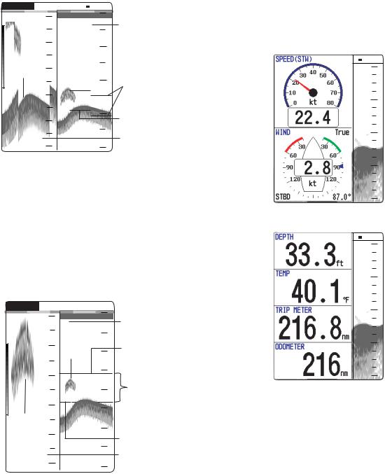
Nav data displays
The nav data displays appear on the left of the screen. Data other than depth requires appropriate sensor.
Two nav data displays are available, Nav Data 1 or Nav Data 2, and you may choose which to
use on the Display menu. The default settings are as follows.
Nav Data 1: Two-data display (SPEED (STW), WIND)
Nav Data 2: Four-data display (DEPTH, TEMPERATURE, TRIP METER, ODOMETER)
You can display between two and four items in a nav data display and choose the item and order to display them. For details, see section 1.19.
W 1/1 |
0 |
20 |
40 |
60 |
80 |
Nav Data 1 display
W 1/1 |
0 |
20 |
40 |
60 |
80 |
Nav Data 2 display
Sample Nav Data displays (Default setting)
4
1.5Choosing Range
The basic range may be chosen in Auto or Manual mode.
1.Press the RANGE key to open the range setting window.
|
|
|
|
|
|
|
|
|
Range |
|
|
||||
|
W |
|
|
Manual X |
|
|
|
Auto |
|
||||||
|
|
|
|
|
|
|
|
|
|
|
|
15 ft |
|
|
|
|
|
|
|
30 ft |
|
|
|
|
|
|
|
60 ft |
|
These are |
|
|
|
|
120 ft |
|
|
||
|
|
|
200 ft |
|
available with |
||
|
|
|
400 ft |
|
Manual mode. |
||
|
|
|
600 ft |
|
|
||
|
|
1000 ft |
|
|
|||
|
|
|
|
||||
|
S / T : Select |
|
|
||||
|
[ENTER] : Set |
|
|
||||
|
[MENU] : Cancel |
|
|
||||
|
|
|
|
|
|
|
|
|
|
|
|
|
|
|
|
Range setting window
2.Use W or X to choose Auto or Manual. Auto: The range changes automatically to display the bottom echo on the screen. The range shifting functions are inoperative in Auto mode. “R:A” is shown at the top left corner on the screen.
Manual: The range may be chosen from the eight ranges. “R:M” is shown at the top left corner on the screen.
If you choose Auto go to step 4. For manual go to the next step.
3.For Manual, use S or T to choose the
range.
Default ranges
Unit |
|
|
|
Basic Range |
|
|
|||
|
|
|
|
|
|
|
|
|
|
1 |
2 |
3 |
|
4 |
5 |
6 |
7 |
8 |
|
|
|
||||||||
|
|
|
|
|
|
|
|
|
|
m |
5 |
10 |
20 |
|
40 |
80 |
150 |
200 |
300 |
|
|
|
|
|
|
|
|
|
|
ft |
15 |
30 |
60 |
|
120 |
200 |
400 |
600 |
1000 |
|
|
|
|
|
|
|
|
|
|
fa |
3 |
5 |
10 |
|
20 |
40 |
80 |
100 |
150 |
|
|
|
|
|
|
|
|
|
|
pb |
3 |
5 |
10 |
|
20 |
50 |
100 |
150 |
200 |
|
|
|
|
|
|
|
|
|
|
HR* |
4 |
8 |
15 |
|
30 |
50 |
100 |
150 |
200 |
|
|
|
|
|
|
|
|
|
|
*: Japanese unit of depth measurement
Note: Basic ranges may be preset as desired. For further details, see page 20.
4. Press the ENTER key.
1. OPERATION
Note: The range mode indication, which appears at the top-left corner, may be turned on or off with Header Info on the Display menu. For details, see page 18.
1.6Adjusting Gain
The gain may be adjusted automatically (Fishing or Cruising) or manually.
Fishing and Cruising
The gain (or receiver sensitivity) is adjusted automatically for Fishing and Cruising mode so that the bottom is displayed as reddish brown. Gain offset lets you override automatic gain adjustment.
1.Press the GAIN knob to open the Auto Gain setting window.
Auto Gain
Fishing
Cruising
Off
Offset 0
W Min  Max X
Max X
S / T : Select
[ENTER] : Set
[MENU] : Cancel
Auto Gain setting window
2.Press the GAIN knob again to choose Fishing or Cruising.
You may also use S or T to choose the mode.
Fishing: This mode clearly displays weaker echoes and is for searching fish schools. “G:AF” is shown at the top left corner on the screen.
Cruising: This mode clearly displays stronger echoes (for example, bottom), suppresses weak echoes and is for general cruising.
“G:AC” is shown at the top left corner on the screen.
Off: For manual adjustment
Adjusting gain offset proceed, if not go to step 4.
3.If you need, adjust the gain offset with W or X (setting range: -5 to +5).
Pressing W lowers the gain, X raises the gain.
4.Press the ENTER key.
5
1. OPERATION
Manual gain adjustment
The GAIN knob adjusts the sensitivity of the receiver. Generally, use a higher gain setting for greater depths and a lower setting for shallower waters.
 CAUTION
Use the proper gain setting.
Incorrect gain may produce wrong depth indication, possibly resulting in a dangerous situation.
Gain too high Gain proper Gain too low
Examples of proper and improper gain
1.Press the GAIN knob to open the Auto Gain setting window.
2.Press the GAIN knob again to choose Off. “G:M” appears at the top left corner on the screen.
3.Press the ENTER key.
4.Rotate the GAIN knob to adjust the gain. The setting range is 0.0 to 10.
Adjust so that a slight amount of noise remains on the screen.
The setting gain is shown at the top of the screen as G (Gain) + XX (setting value).
1.7Measuring Depth
The VRM (Variable Range Marker) functions to measure the depth to fish schools, etc.
1.Use S or T to place the VRM on the object to measure depth.
2.Read the VRM depth just above the VRM.
G:AF R:A |
50k W 1/1 |
|||||||||
|
|
|
|
|
|
0 |
|
|
|
|
|
|
|
|
|
|
|
|
|
|
|
|
|
|
|
|
|
|
|
|
|
|
VRM
Depth to VRM 20
37.9
40


 60
60 

49.6m 


80
How to measure depth with the VRM
1.8Menu Operating Procedure
The FCV-620/585 have five menus: Sounder, Display, Alarm, Data, and System. Below is the basic menu operating procedure.
1. Press the MENU/ESC key to open the menu.
Cursor |
Currently selected menu |
(yellow) |
|
Menu
Sounder
Display
Alarm
Data
TSystem
Menu window
Menu item window
*: FCV-585 only
Sounder
Pic. Advance |
: 1/1 |
|
Zoom Mode |
: Bottom Lock |
|
Shift |
: |
0ft |
Bottom Zone |
|
|
Interference |
: Auto |
|
Color Erase |
: |
0% |
Clutter |
: |
0% |
White Line |
: |
0% |
White Marker |
|
|
TVG |
: Medium |
|
Smoothing |
: On |
|
TX Power |
: Auto |
|
TX Rate |
: 10 |
|
Transducer* |
: 600W |
|
|
||
S / T / W / X : Select |
||
[ENTER] |
: Enter |
|
[MENU] |
: Back |
|
Menu
2.Use S or T to choose the menu or sub menu desired.
The cursor (yellow) shows current selection. The items in the right window change with menu selected.
3.Press the ENTER key.
The cursor (yellow) shifts to the menu item window (right) and the current selection on
6
the menu window (left) is displayed to gray. You may also use X to move the cursor.
4.Use S or T to choose the menu item desired and press the ENTER key.
The selected setting box or window appears.
|
|
|
|
|
|
|
|
|
|
|
|
|
|
|
|
|
|
|
|
Depth Size |
|
||
|
|
|
|
|
|
|
|
|
|
|
|
|
|
|
|
|
|
|
|
|
Small |
|
|
|
|
|
|
|
|
|
|
|
Medium |
|
|
|
|
|
|
|
|
|
|
|
Large |
|
|
|
|
|
|
|
|
|
|
|
|
|
|
|
|
|
Off |
|
|
|
|
[ENTER] : Set |
|
||
|
|
|
On |
|
|
|
|
[MENU] : Cancel |
|
||
|
|
|
|
|
|
|
|
|
|
|
|
Setting box |
|
Setting window |
|||||||||
5.Use S or T to choose an option.
6.Press the ENTER key to save the setting. The setting box or window disappears. To escape without changing setting press the MENU/ESC key instead of the ENTER key.
7.To choose another menu press the MENU/ ESC key.
The cursor (yellow) moves to the menu window. You may also use W to move the cursor.
8.Press the MENU/ESC key to close the menu.
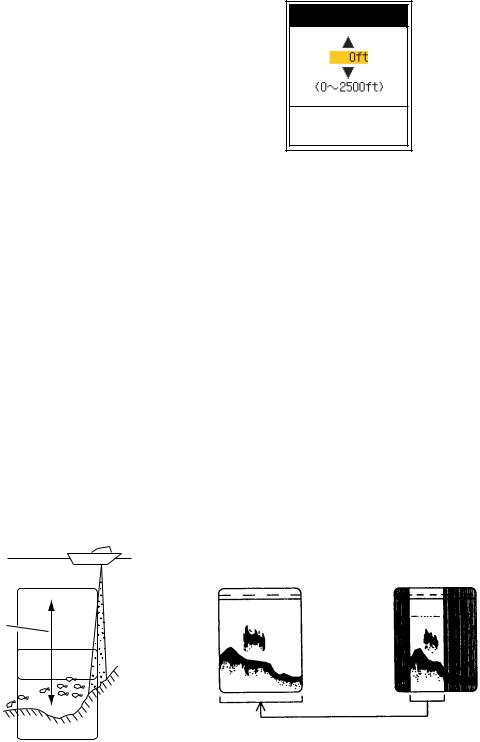
1.9Shifting Range
The basic range may be shifted up or down in the Manual mode as follows:
Window can be shifted up and down to select starting depth.
Display
Range and display shift concept
Note: This function is inoperative when Auto mode is selected on the range setting window.
1.Press the MENU/ESC key to open the menu.
2.Use S or T to choose Sounder and press the ENTER key.
3.Use S or T to choose Shift and press the
ENTER key.
1. OPERATION
Shift
[ENTER] : Set
[MENU] : Cancel
Shift setting window
4.Use S or T to choose an amount of shift desired and press the ENTER key.
5.Press the MENU/ESC key twice to close the window.
Note: The echo may be lost if the amount of shift is greater than actual depth.
1.10Choosing Picture Advance Speed
The picture advance speed determines how quickly the vertical scan lines run across the screen. When choosing a picture advance speed, keep in mind that a fast advance speed will expand the size of the fish school horizontally on the screen and a slow advance speed will contract it. A fast advance speed is useful for observing the rugged bottom minutely. A slow advance speed is useful for observing the smooth bottom.
Fast |
Slow |
Picture and picture advance speed
1.Press the MENU/ESC key to open the menu.
2.Use S or T to choose Sounder and press the ENTER key.
7
1. OPERATION
|
|
|
|
|
|
|
|
|
|
Sounder |
|
|
|
||
|
|
|
|
|
|
|
|
|
|
Pic. Advance |
: 1/1 |
|
|
|
|
|
|
Zoom Mode |
: Bottom Lock |
|
|
|
|
|
|
Shift |
: |
0ft |
|
|
|
|
|
Bottom Zone |
|
|
|
|
|
|
|
Interference |
: Auto |
|
|
|
|
|
|
Color Erase |
: |
0% |
|
|
|
|
|
Clutter |
: |
0% |
|
|
|
|
|
White Line |
: |
0% |
|
|
|
|
|
White Marker |
|
|
|
|
|
|
|
TVG |
: Medium |
|
|
|
|
|
|
Smoothing |
: On |
|
|
|
|
|
|
TX Power |
: Auto |
|
|
|
|
|
|
TX Rate |
: 10 |
|
|
|
|
|
|
Transducer* |
: 600W |
|
|
*: FCV-585 |
|
|
|
|
|
|
|
|
only |
|
|
S / T / W / X |
: Select |
|
|
||
|
|
|
|
|
|||
|
|
[ENTER] |
: Enter |
|
|
|
|
|
|
[MENU] |
: Back |
|
|
|
|
|
|
|
|
|
|
|
|
|
|
|
|
|
|
|
|
Sounder menu
3.Use S or T to choose Pic. Advance and press the ENTER key.
|
|
|
|
|
|
|
|
Pic. Advance |
|
|
|
||
|
4/1 |
|
|
|
|
|
|
2/1 |
|
|
Fast |
||
|
|
1/1 |
|
|
|
|
|
|
|
|
|
|
|
|
1/2 |
|
|
|
|
|
|
1/4 |
|
|
|
|
|
|
1/8 |
|
|
|
|
|
|
1/16 |
|
|
|
|
|
|
|
|
|
|
||
|
|
Stop |
|
Slow |
||
|
|
|
|
|
||
|
|
|
|
|
|
|
|
S / T : Select |
|
|
|
||
|
[ENTER] : Set |
|
|
|
||
|
[MENU] : Cancel |
|
|
|
||
|
|
|
|
|
|
|
|
|
|
|
|
|
|
Pic. Advance setting window
4.Use S or T to choose picture advance speed desired and press the ENTER key. 1/16 is the slowest speed and 4/1 is the fastest speed. 1/16 means one scan line is produced every 16 transmissions. Current picture advance is displayed at the top-right corner of the screen.
 CAUTION
The picture is not refreshed when picture advancement is stopped.
Maneuvering the vessel in this condition may result in a dangerous situation.
5.Press the MENU/ESC key twice to close the window.
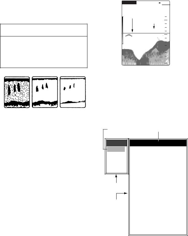
1.11Suppressing Interference
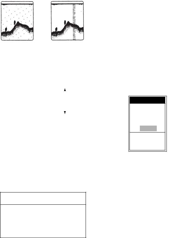
Interference from other acoustic equipment operating nearby or other electronic equipment on your boat may show itself on the display as shown in the figure below. Follow the procedure below to suppress interference.
Interference from |
Electrical interference |
other sounder |
|
Interference
1.Press the MENU/ESC key to open the menu.
2.Use S or T to choose Sounder and press the ENTER key.
3.Use S or T to choose Interference and press the ENTER key.
Interference
Off
Low
Medium
High
Auto
S / T : Select
[ENTER] : Set
[MENU] : Cancel
Interference setting window
4.Use S or T to choose the degree of suppression desired and press the ENTER key. Off: Turn off interference rejector.
Low, Medium, High: High provides the greatest degree of suppression and Low is the smallest.
Auto: Interference is suppressed automatically.
Note: Turn off the interference rejector when no interference exists, so as not to miss echoes from small fish.
5.Press the MENU/ESC key twice to close the window.
8
Loading...